Nuclear Cycler: An Incremental Approach to the
Deflection of Asteroids
Massimiliano Vasile1, Nicolas Thiry2,∗ 75 Montrose Street, Glasgow, UK G1 1XQ
Abstract
This paper introduces a novel deflection approach based on nuclear explo-sions: the nuclear cycler. The idea is to combine the effectiveness of nu-clear explosions with the controllability and redundancy offered by slow push methods within an incremental deflection strategy. The paper will present an extended model for single nuclear stand-off explosions in the proximity of elongated ellipsoidal asteroids, and a family of natural formation orbits that allows the spacecraft to deploy multiple bombs while being shielded by the asteroid during the detonation.
Keywords: Asteroid deflection; planetary defence; nuclear interceptor
1. Introduction
Deflection methods are commonly divided into two main categories, im-pulsive and slow push, depending on whether the modification of the or-bit of the asteroid is, respectively, quasi-instantaneous or modified over a longer period of time. Examples of impulsive methods include the nu-clear interceptor (Hammerling and Remo , 1995) and the kinetic impactor (Jutzia and Michel ,2014), while slow-push methods include, among others, the gravity tractor (Lu and Love ,2005), laser ablation (Vasile and Maddock ,
∗Corresponding author
Email addresses: [email protected](Massimiliano Vasile),
[email protected](Nicolas Thiry)
1
Professor at the University of Strathclyde 2
2012), ion-beam shepherd (Bombardelli and Pel?ez , 2011) and mass driver (Olds, Charania, Graham and Wallace , 2004).
The nuclear interceptor can nudge the asteroid off of its collision course with the Earth even when the warning time is low, but a single explosion represents a single point of failure and does not allow any control over the evolution of the trajectory of the asteroid. On the other hand, slow-push methods allow for a more precise control of the deflection manoeuvre but typically require a longer warning time, additional propellant in order to maintain a hovering position in the vicinity of the asteroid, the abil-ity to operate autonomously and are dependent on the distance from the Sun (Bombardelli and Pel?ez ,2011;Sanchez, Colombo, Vasile et al. ,2009;
Vasile and Maddock , 2012).
Nuclear methods carry the highest energy density among all currently proposed mitigation strategies. As there is no atmosphere in space, the efficiency of nuclear methods is based on the amount of asteroid material that can be blasted away following the explosion. In a report to Congress,
NASA (2007) argued that using a stand-off nuclear detonation would be ten to a hundred times more effective than any other alternative. While a subterranean explosion would, in principle, further increase the amount of material that can be expelled, a stand-off configuration does not require landing and digging and is thus more manageable with current technology.
The theoretical efficiency of nuclear-based approaches must be balanced with the difficulty in controlling the outcome of the explosion. This lack of control can lead to three main problems. The high level of energy re-leased during the single detonation introduces the potential risk of an un-wanted fragmentation. If the asteroid breaks up into several pieces follow-ing the explosion, it may be that some of the larger pieces will impact the Earth and the probability of causing damages may never go to zero (Sanchez, Vasile and Radice ,2010); the risk of fragmentation is already re-duced however due to the choice of the stand-off configuration.
Hence, relying on a single interceptor is a rather risky strategy.
The idea proposed in this paper partially overcomes these difficulties by fractionating a single explosion into a number of smaller and better con-trolled ones. A single spacecraft, carrying a number of bombs, is placed on a formation orbit with the asteroid and incrementally releases the bombs so that each of them explodes at an optimal position with respect to the surface of the asteroid. As will be shown, careful choices in the firing time and or-bital trajectory can allow for the incremental deflection of the asteroid while ensuring an appropriate radiation shielding to the carrier.
The paper is structured as follows: first by a review of the model of a single nuclear interceptor method considering both spherical and elongated asteroids. The idea of the nuclear cycler is then explained, illustrating the concept with a possible choice of mission configuration. The following section shows the results of a comparison for the deflection of an elongated Apophis-like asteroid using a single interceptor and an incremental deflection using the nuclear cycler idea. Lastly is a discussion on the strategy and plans for future work.
2. Single Detonator Model
This section introduces a model to calculate the change in linear mo-mentum of the asteroid due to a stand-off nuclear explosion. The first subsection presents a slightly modified version of the model presented by
Sanchez, Colombo, Vasile et al. (2009) applicable to the case of a spherical asteroid. The model is then extended to the case of an elongated body with an ellipsoidal shape. The semi-analytical model presented in this section is only an approximation of the complex phenomena that occur during a stand-off explosion. A number of effects are not considered here and there are strong assumptions on the absorption of radiation and on the vaporisation process. In particular, we assume that the surface of the asteroid is composed of hard rock with low porosity. As in Solem (1993), we assume a linear relationship between the mass of the nuclear bomb and total yield, with all the energy absorbed by the material going into the vaporisation process, where only va-porisation is considered rather than melting and vava-porisation. Furthermore, no shock wave propagation, reflection and diffraction are modelled. More accurate results can be found in the work of Plesko et al. (2010) who used a full numerical simulation. As with Shubin et al. (1995); Meshcheryakov
imparted to the asteroid and serves the main scope of this paper, which is to compare a single detonation with a fractionated approach.
2.1. Spherical Asteroid
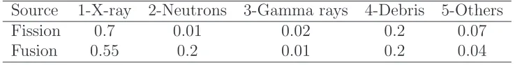
The energy released during the explosion is carried by the debris of the exploded spacecraft and by the radiations produced. Table 2.1 shows the fractionfi(withi∈ {1,2,3,4,5}) of energy associated to each of the products
of the explosion for the case of a fusion and fission devices (Glasstone ,1962;
[image:4.595.121.490.340.387.2]Hammerling and Remo , 1995).
Table 1: Energy fractionfi over all the products of a nuclear explosion
Source 1-X-ray 2-Neutrons 3-Gamma rays 4-Debris 5-Others
Fission 0.7 0.01 0.02 0.2 0.07
[image:4.595.130.461.350.570.2]Fusion 0.55 0.2 0.01 0.2 0.04
Figure 1: Standoff configuration for the nuclear interceptor method
The energy delivered during the explosion, Y0, is computed from the yield-to-mass ratio and is conservatively assumed to have a value Y T W = 0.75 ktons/kg for fusion devices and Y T W = 0.075 ktons/kg for fission de-vices3.
Y0 =Y T W mwh (1)
3
where mwh is the mass of the bomb. This assumption is more conservative
than the one of Solem (1993). In this paper, no buried or surface detona-tion are considered due to the added difficulty of landing and digging on an asteroid.
With reference to Figure 1, the explosion is assumed to happen at a dis-tance H from the surface of the asteroid, therefore, only a portionmdebris of
the total mass of debris md will hit the surface:
mdebris =Smd (2)
If one assumes that the exploding device sees a spherical cap with radius RA,
then the fraction S can be expressed as:
S = 1 2−
√
H
2 √
H+ 2RA
RA+H
(3)
The ejection velocity of the debris vdebris is then computed from the fraction
f4 = 0.2 (see Table 2.1) of the total energy Y0 released during the blast:
vdebris =
r
2f4Y0
md
(4)
The variation of velocity δvdebris due solely to the debris cloud is then given
by:
δvdebris =βSsc
mdebrisvdebris
mA
(5) where Ssc is a scattering factor and β the momentum enhancement factor
(Tedeschi, Remo, Schulze and Young , 1995) which was set to β = 2 in the simulations.
The contribution from the radiation is derived from the Beer-Lambert law of absorption. Given a radiation with frequency ν and knowing the incident radiation energy per unit area Iν
0(λ) and the depth z, the energy per unit area Iν(λ, z) transmitted beyond a given depth is computed as follows:
Iν(λ, z) = sinǫ(λ)I0ν(λ) exp
−ρAκν
z
sinǫ(λ)
(6)
The incident radiation density Iν
0(λ) is given by:
I0ν(λ) = fi
where the h distance is computed as:
h=
q
(H+ (1−cosλ)RA)2+R2Asin2λ (8)
and ǫ is given by:
sinǫ= (RA+H) cosλ−RA
h (9)
The linear mass-absorption coefficient κν for each type of radiation is given
in Table 2 (Hammerling and Remo , 1995). Note that quantities in Table 2
are considered as mean values over the range of frequencies of X-rays and gamma-rays.
Table 2: Opacityκν, or linear mass-absorption coefficient, for an asteroid made of forsterite
Radiation type X-Ray Neutron Gamma ray
Value 1.5 m2/kg 0.0044 m2/kg 0.005 m2/kg
The amount of energy absorbed per unit mass at a given depth is then obtained by considering the cumulative absorption of each radiation type:
E(λ, z) =−X
ν
dIν
dz = X
ν
κνI0νexp
−ρAκν
z
sinǫ(λ)
(10)
Part of this energy goes into the vaporization process of the asteroid, while the excess energy is converted into thermal excitation. The local average velocity of the gas molecules ¯v is then estimated by an energy balance, where
Ev is the total vaporization enthalpy per unit mass:
¯
v(λ, z) =p2(E(λ, z)−Ev) (11)
This allows one to define a limit depth zmax below which the vaporization
process cannot continue as the energy absorbed is lower than the vaporization enthalpy. Given a certain distance H and yield Y0, the value of zmax is
numerically computed by finding the value of z that satisfies the relationship
E(λ, z) =Ev for each λ considered.
The change in linear momentum generated by the expelled material is expressed, for an infinitesimal volume, as:
dP = cosλ
where the cosine function comes from the fact that we only retain the tangen-tial component, and the 12 factor is due to the assumption of an equiprobable scattering of the gas molecules from the ablated surface over a hemisphere. The area of a spherical cap is given by:
S = 2πR2A(1−cosλ) (13) with the infinitesimal volume dV given by:
dV = 2πR2Asinλ dz dλ (14)
Integrating Eq. (12) and dividing by the mass of the asteroid gives the change of velocity δvradiation due to radiation:
δvradiation=
πR2 A
MA
Z λmax
0
Z zmax(λ)
0
ρA¯v(λ, z)dz sinλcosλ dλ (15)
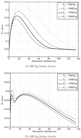
Figure 2(a) shows the total δv = δvradiation +δvdebris imparted to an
as-teroid, with a mass and density from Table 3, assuming a fusion device of 600 kg at different altitudes of detonation and for different values of the en-thalpy of vaporization. Figure 2(b), by comparison, shows the δv imparted to the same asteroid by a fission device of equal mass, at different altitudes of detonation and for different values of the enthalpy of vaporization.
2.2. Elongated Asteroid
In this section, we consider the case of an elongated asteroid with an elongation factor el, defined as an ellipsoid with semi-major axis aI =e2l/3RA
and semi-minor axes bI =cI =RAe
−1/3
l . The mean radius is identical to the
one used in the spherical case previously derived, such that the elongated and spherical asteroids considered have identical volumes. Considering the configuration where the bomb is detonated along the longer side as a worst case scenario, the distance h(λ) is now given as:
h=
v u u
t(H+ (1−cosλ)e2/3
l RA)2+
RA
e1l/3 !2
sin2λ (16)
0 20 40 60 80 100 120 140 0
0.05 0.1 0.15 0.2 0.25 0.3 0.35
Detonation Altitude [m]
δ
v [m/s)
E
v = 5MJ/kg
E
v = 10MJ/kg
E
v = 15MJ/kg
E
v = 20MJ/kg
(a) 600 kg fusion device
0 20 40 60 80 100 120 140
0.012 0.014 0.016 0.018 0.02 0.022 0.024
Detonation Altitude [m]
δ
v [m/s)
E
v = 5MJ/kg
E
v = 10MJ/kg
E
v = 15MJ/kg
E
v = 20MJ/kg
[image:8.595.169.442.176.638.2](b) 600 kg fission device
Figure 2: Impulsive change of velocity as a function of the detonation altitude for different values of the enthalpy of vaporization
be related through the following formula:
cos ˜λ = p cosλ
1 + (e2
l −1) sin2λ
(17)
The value of sinǫ is obtained by computing the scalar product between the direction normal to the ellipsoidal surface n and the direction −h, which gives
sinǫ=
e2l/3RA+H
e2l/3RA cosλ−1 e1l/3h
RA
q
cos2λ
e2
l + sin
2λ (18)
The infinitesimal volume is now expressed as:
dV = 2πe1l/3R2Asin
2λ
sin ˜λ dz dλ (19)
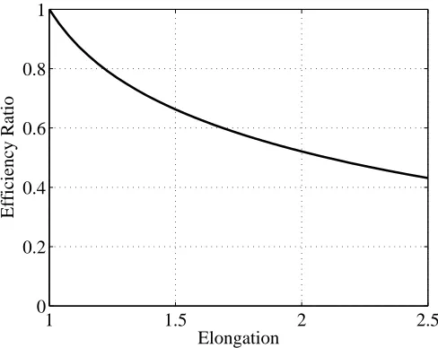
Keeping a constant detonation altitude of 17 m, Figure 3 shows how the δv
produced compares to the spherical case, considering again a 600 kg fusion device.
1 1.5 2 2.5
0 0.2 0.4 0.6 0.8 1
Elongation
[image:9.595.177.421.471.665.2]Efficiency Ratio
2.3. Comparison with Other Simplified Analytical Models
As mentioned in the previous sections, the model proposed in this pa-per is largely based on the existing literature on the subject and represents only an approximation of the full phenomenon. It is however interesting to compare our predicted δv against the prediction of two other simpli-fied analytical formulations proposed by Solem (1993) and Meshcheryakov
(2014a)Meshcheryakov (2014b).
The model inSolem (1993) is given by the simple parametric exponential law:
δv = αδ
mA
(Y T W mwh)
β+1
2 (20)
where, using Solem’s notation, the parameter α is the crater constant, β
the crater exponent and δ2/2 is said to be the energy that goes into the dirt ejected from the crater. The values of the three parameters are derived experimentally. For the case of a stand-off explosion, Solem (1993) proposes the following values: β = 1, α between [1, 2]×10−6
s/cm and δ between 0.2 and 0.4. He also suggests that the most effective solution would be a neutron bomb with high neutron deposition, therefore we can compare the value computed with Eq. (20) against our model for neutron bombs. If we take the lower bounds,α= 10−4
s/m andδ= 0.2, then Eq. (20) gives 1.4 m/s which is about 4 times higher than our prediction.
By comparison, Meshcheryakov’s model gives an approximation of the δv
as:
δv =Q0.554 1− √
h2+ 2hR
R+h !
W mA
(21)
where, using Meshcheryakov’s notation, Q is the yield of the explosion and
W is a tabulated factor that depends on the altitude of the explosion. In-terpolating the values available in Meshcheryakov (2014a), at 25 m from an asteroid with radius of 134 m and assuming a fission device with a mass of 600 kg, Eq. (21) predicts a δv of 0.0189 m/s which is consistent with the prediction of our model for a fission device with the same yield exploding at the same distance.
the asteroid, as part of the material is ejected at each explosion. There-fore, the effect of each explosion would progressively increase. This cratering effect, however, is not considered in the current model.
3. Nuclear Cycler Mission Concept and Design
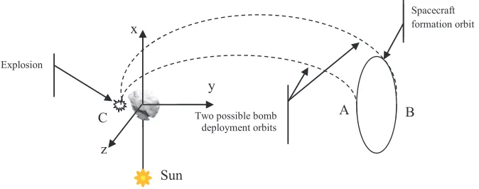
The key idea is to incrementally change the velocity of the asteroid by releasing and detonating a series of relatively small nuclear bombs from a vantage point at a safe distance from the asteroid. Figure 3shows a possible configuration with a carrier-spacecraft flying in formation with the asteroid on a periodic orbit at a set distance from the asteroid and releasing two bombs at two different times. The detonation occurs on the far side of the asteroid with respect to the spacecraft so that the asteroid is shielding the spacecraft from radiation and debris.
Spacecraft formation orbit formation
Two possible bomb deployment orbits
formation
Sun x
y
z Explosion
formation
orbit
A B
[image:11.595.138.475.395.528.2]C
Figure 4: Illustration (not to scale) of the nuclear cycler concept
In this particular configuration, the orbit of the carrier and the one of the bomb are timed in such a way that by the time the bomb goes from point A to point C, the carrier has moved from point A to point B. Equivalently, by the time the bomb goes from B to C, the carrier has moved from B back to A, closing the cycle, after which a new cycle will begin. The data from the previous explosions can be collected and analysed to better control the altitude and timing of the subsequent explosions or to control the direction of the resulting δv.
asteroid, and point B to the aphelion. In this case two bombs are released every revolution of the asteroid around the Sun.
ˆ i
ˆj ˆ k
ˆ x ˆ z
ˆ y
r
sc
[image:12.595.226.394.221.381.2]r dr
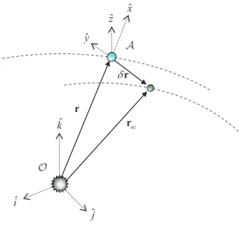
Figure 5: Local Hill’s reference frame centred on the asteroid
3.1. Preliminary Trajectory Design
A first approximation of the trajectory of the spacecraft and bombs can be obtained using the linearised proximity motion equations (Schaub and Junkins ,
2003):
x≈ r aδa+
aesinθ
√
1−e2δM −acosθδe
y ≈ r
(1−e2)3/2 (1 +ecosθ) 2
δM +rδω+ rsinθ
(1−e2)(2 +ecosθ)δe+rcosiδΩ
z ≈r(sinθ∗
δi−cosθ∗
siniδΩ) (22)
where [a, e, i, Ω, ω] are the standard Keplerian orbit parameters of semi-major axis, eccentricity, inclination, right ascension (of the ascending node), and the argument of periapsis respectively, θ and M are the true and mean anomalies, θ∗
= θ +ω and δr = [x, y, z]T. The coordinate frames are
shown in Figure 5 where O is a heliocentric inertial reference frame, and A is the relative Hill reference frame, centred on the asteroid. The vector
In order to maintain the formation, the spacecraft and asteroid are put in a similar orbit around the Sun with identical semi-major axis so that
δa = 0, causing their orbital period to be equal and therefore there is no relative drift. The value of the remaining orbital parameters of the orbit of the carrier spacecraft can be computed by solving the following system of equations:
x(θ = 0) = 0 x(θ=π) = 0
y(θ= 0) =yA y(θ =π) =yB
z(θ = 0) = 0 z(θ=π) = 0
(23)
Given the proximity equations (22), one can see that system (23) can be satisfied if δe = 0, δi = 0 and δΩ = 0. In this case the problem reduces to the solution, for δM and δω, of the following system of two equations:
y(θ = 0) = (1r−(θe=0)2)3/2(1 +e)
2δM +r(θ = 0)δω =y A
y(θ =π) = (1r−(θe=2)π3)/2(1−e)
2δM +r(θ =π)δω =y B
(24)
A first approximation of the trajectory of each of the bombs can be derived in a similar fashion assuming, this time, that:
y(θ = 0) = (1r−(θe=0)2)3/2(1 +e)
2δM +r(θ= 0)δω =y A
y(θ =π) = (1r−(θe=2)π3)/2(1−e)
2δM +r(θ=π)δω =y C
(25)
and
y(θ =π) = (1r−(θe=2)π3)/2(1−e)
2δM +r(θ =π)δω =y B
y(θ = 0) = (1r−(θe=0)2)3/2(1 +e)
2δM +r(θ = 0)δω =y C
(26)
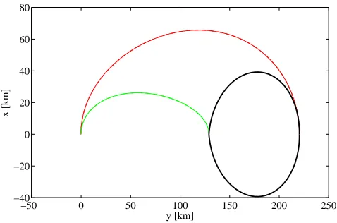
Figure6shows an example of trajectories for the bombs and the spacecraft after setting yB = 131 km,yA= 214 km and yC =−0.210 km respectively.
3.2. Refined Trajectory Design
−50 0 50 100 150 200 250 −40
−20 0 20 40 60 80
y [km]
[image:14.595.182.421.183.341.2]x [km]
Figure 6: Example of trajectories of the bombs and the spacecraft in the Hill’s reference frame with no perturbations from the gravity field of the asteroid
the orbit plane. In this case, only the in-plane components of the proximal motion dynamics are required:
¨
x=−r¨+ 2 ˙θy˙+ ˙θ2+ ¨θy− µsun(r+x) r3
sc −
µA δr3x+
∂U20+22
∂x
¨
y=−2 ˙θ( ˙r+ ˙x)−θ¨(r+x) + ˙θ2y− µsun r3
sc y−
µA δr3y+
∂U20+22
∂y
¨
z =−µsun r3
sc z−
µA δr3z+
∂U20+22
∂z
(27)
with
¨
θ =−2 ˙rrr2θ˙ ¨
r = ˙θ2r−µsun r2
(28)
where µsun and µA are the gravity constants of the Sun and the asteroid,
respectively. The asteroid shape was assumed to be an ellipsoid with aI ≥
bI = cI, the three semi-axes along the three body-fixed orthogonal axes, as
in Section 2.2. The value of the semi-axes is given in Table 3. Note that the total expelled mass is negligible compared to the mass of the asteroid, thus we used the conservative assumption that the mass of the asteroid remains unchanged. Furthermore, in the reduced model presented in this paper, the spinning rate and axis are assumed to remain constant.
The axiscI is assumed to be aligned with the vector of angular
Table 3: Orbital and physical properties of test asteroid
Element Measured Value
Semi-major axis a0 0.9224 AU
Eccentricity e0 0.1912
Period T0 323.5969 days
Mean motion n0 1.2876 ×10⁻⁵ deg/s
Mass mA 2.7×10¹⁰ kg
Gravitational constant µA 1.801599×10⁻⁹ km3/s2
Physical dimensions aI, bI, cI 196 m, 112 m, 112 m
Rotational velocity wA 3.3×10⁻³ deg/s
Total vaporisation Enthalpy Ev 15 MJ/kg
Density ρA 2650 kg/m3
2002; Rossi et al. , 1999):
U20+22 =
µA
δr3
C20(1− 3 2cos
2ϕ) + 3C
22 cos2ϕcos 2α
(29)
whereϕ is the elevation over thex-yplane and the harmonic coefficients C20 and C22 are a function of the semi-axes,
C20 =−101 (2cI2−a2I −b2I)
C22 = 201 (a2I −b2I)
and α is defined as,
α= arctany
x
+wAt
The initial conditions for the backward integration, in the case when the bomb is released from point B, are:
x(θ= 0) = 0
y(θ = 0) =yC
z(θ= 0) = 0 ˙
x(θ= 0) =δvCcosγ
˙
y(θ = 0) =δvCsinγ
˙
z(θ= 0) = 0
(30)
The modulus of the velocity δvC was varied from (vex+ǫex1) to (vex+ǫex2), withvex =
p
γ angle was constrained to be in the interval [0.6, π/2] rad. The trajectory was then propagated backward for a true anomaly ∆θ =πusing an adaptive Runge-Kutta, Dormand-Prince scheme implemented in the Matlab function
ode45, with absolute and relative tolerance equal to 1e-6 and 1e-7
respec-tively. If the bomb is released from point B, the arrival conditions need to satisfy the constraints:
x(θ=π)2+ (y(θ =π)−yB)2+z(θ =π)2 = 0 (31)
This analysis, however, assumes that for each value of δvC, a particular
spacecraft formation orbit is targeted, rather than targeting always the same orbit. Therefore, the Matlab function fmincon was used to find the optimal
value ofγ that satisfies the relaxed soft constraintx(θ =π)2+z(θ =π)2 = 0 for different values ofδvC. As it is shown in Figure7, this yields a continuous
and compact set of trajectories. The minimum distance from the asteroid however is limited by the need to have the bomb completing the transfer in half a revolution of the asteroid around the Sun. For low values of δvC,
the gravity of the asteroid accelerates the velocity of the bomb leading to a crossing of the y-axes in less than half a period. The value of δvC in this
analysis, therefore, was set to quickly clear the Hill’s sphere of influence of the asteroid.
Figure7shows a set of optimised trajectories superimposed to the theoret-ical ones obtained using the linear proximity equations. Figure 7(a) shows the case in which yC = −0.1287 km, ǫex1 = −1.44917× 10⁻⁵ km/s and
ǫex2 = −1.42417 ×10⁻⁵ km/s while Figure 7(b) shows the case in which
yC =−0.210 km,ǫex1 = 8.1178×10⁻⁶ km/s and ǫex2 = 8.3678×10⁻⁶ km/s. These two cases correspond to an optimal explosion along the semi-minor and semi-major axes of the asteroid respectively. Note that, according to Figure 2, a variation of 81.3 m in the detonation altitude significantly de-creases the effectiveness of the explosion. On the other hand, it is possible to find trajectories from point A or point B to any point C in the interval [−0.1287, −0.210] km hence it is possible to target the optimal detonation distance for each explosion.
Figure 8 shows a close-up of Figure 7(a) around point C. One can see that the bomb would approach the asteroid almost head on, although δvC
−50 0 50 100 150 200 250 300 −50
0 50 100
y [km]
x [km]
(a)
−50 0 50 100 150 200 250 300 350 400
−100 −50 0 50 100 150
y [km]
x [km]
[image:17.595.163.440.181.598.2](b)
Figure 7: Families of formation and deployment trajectories for spacecraft and bombs: (a) detonation point at 210 m, (b) detonation point at 128 m. Magenta and blue curves are the true trajectories corrected for the gravity of the asteroid, the trajectory of the spacecraft is in black, and the blue, red and green curves show the estimated trajectories from the linear model.
−0.55 −0.5 −0.45 −0.4 −0.35 −0.3 −0.25 −0.2 −0.15 −0.1 0
0.5 1 1.5 2 2.5 3
y [km]
[image:18.595.168.435.187.367.2]x [km]
Figure 8: Close up of the families of deployment trajectories for a detonation point at 210 m. Magenta and blue curves are the true trajectories corrected for the gravity of the asteroid, the blue, red and green curves are the estimated trajectories from the linear model.
and the trajectory of the spacecraft. The magnitude of the deployment ∆v
manoeuvre, at the beginning of the deflection cycle, is reported in Figure 9
for point A and B and for the two detonation altitudes. This translates into a maximum mass fraction of 5.546×10⁻⁵
per bomb assuming a cold gas engine with an Isp = 68 s. Finally, the formation orbit of the carrier designed with
the linear proximity motion equations (22) were re-optimised to keep into account the full dynamics.
A small ∆v correction manoeuvre was inserted at A and B to match the A-to-B trajectory with the B-to-A trajectory such that the A and B point remain the initial conditions of the bomb deployment trajectories and the periodicity of the formation orbit is maintained. The optimised correction manoeuvres, however, are of negligible size, even lower than the deployment manoeuvres, and are not reported here.
3.3. Estimation of the Miss Distance
Given the variation of the velocity of the asteroid δv = [δvt, δvn, δvh]T
100 150 200 250 300 350 400 0.005 0.01 0.015 0.02 0.025 0.03 0.035 0.04
Release distance [km]
Release
∆
v [m/s]
[image:19.595.158.440.185.366.2]bomb 1 − detonation @ 128.7m bomb 2 − detonation @ 128.7m bomb 1 − detonation @ 210 m bomb 2 − detonation @ 210 m
Figure 9: Total ∆v at the point of release of the bomb from the spacecraft
elements at a time tend (Vasile and Colombo , 2008):
δa= 2a 2v
µsun
δvt
δe= 1
v h
2(e+ cosθ)δvt−
r
asinθδvn i
δi= √rcosθ
µsunp
δvh
δΩ = √ rsinθ
µsunpsini
δvh (32)
δω = 1
ve h
2 sinθδvt+
2e+ r
acosθ
δvn
i
− rsinθ
∗
cosi
õ
sunpsini
δvh
δM =
geometric variation
zp }| {
(1−e2)
ve
2
1 + e 2r
p
sinθδvt+
r
acosθδvn
+δn(tend−td)
| {z }
variation in a
where
δn=
r µsun
a3 −
r µ
sun
(a+δa)3 and p = a(1− e2). The time t
end corresponds to the time between the
final time is the expected time of the impact of the un-deviated asteroid with the Earth. At each new detonation, therefore, all the orbital elements of the asteroid are updated with the variation computed with Eqs. (32). Then, given the cumulative variation of the orbital elements at tM OID, one
can compute the displacement δr = [x y z]T of the asteroid in the Hill’s
reference frame centred in the un-deviated asteroid at the true anomaly θ of the MOID using Eqs. (22).
From the deflectionδrthe impact parameterbat the time of the MOID can be computed(see Figure 10(a) where VN EO is the velocity of the deviated asteroid with respect to the Earth). The impact plane can be defined as the plane centred in the Earth and perpendicular to the velocity vector of the un-deviated asteroid with respect to the Earth, UN EO, at the time of the impact (see Figure 10(b) where vE is the velocity of the Earth). The
deflection vector xb in theb-plane coordinates can be expressed as:
xb = [ξ η ζ]T =
h b
ξ ηb bζiT δr (33)
where
b
η = UN EO
UN EO
, ξˆ= vE ∧bη kvE ∧bηk
, ζˆ=ξb∧bη (34)
The impact parameter b is then defined as:
b =pξ2+ζ2 (35)
At every explosion, the velocity of the asteroid is modified along with its orbital elements. As a consequence, the carrier needs to manoeuvre to main-tain its relative orbital motion with respect to the asteroid. For the strategy presented in this paper, there is no out-of-plane component of the deflection, therefore, the spacecraft needs only an in-plane ∆vc correction. The compo-nent of this correction along the tangential direction has to compensate for the variation of the semi-major axis of the asteroid and, therefore, is of the same magnitude of δvt in Eq. (32). Given that the explosion occurs at the
apsidal points, then δvt = δv. Therefore, it is assumed that the spacecraft
compensates only for a variation ina andewith a single manoeuvre equal to
b
dr
VNEO
Earth
b-plane
(a) (b)
Figure 10: The impact plane andbparameter
reaching the detonation point with different values of δvC, hence at every
explosion a new bomb deployment trajectory can be defined provided that the spacecraft maintains formation.
4. Comparison Between a Single Detonator and the Nuclear Cycler
The nuclear cycler method has been applied to the case of an Apophis-like asteroid considering two different warning times of 6 years and 3 years respectively. The warning time is defined as the time from the first explosion to the expected impact of the un-deviated asteroid with the Earth. Relevant properties of this asteroid can be found in Table 3. The initial inclination i, right ascension of the ascending node Ω, argument of the pericentre ω and mean anomaly M were set so that the asteroid impacts the Earth on 13140 MJD2000.
An interesting initial result is obtained by computing the total δv pro-duced by either a single or a fractionated detonation for the same total mass of the bombs. The results of our model, in Figure 11, indicates that a frac-tionated explosion is better than a single explosion for the same total mass. The explanation of this result lies in the dependency of the δv on the view angle λ in Eq. (15), and the penetration depth zmax. Figure 12 shows the
sin-0 500 1000 1500 2000 2500 3000 0
0.05 0.1 0.15 0.2 0.25 0.3 0.35
Spacecraft dry mass [kgs]
δ
v [m/s)
[image:22.595.173.438.178.384.2]1 bombs 2 bombs 6 bombs 12 bombs
Figure 11: Total δv as a function of the dry mass of the spacecraft for different numbers of explosions
0 500 1000 1500 2000 2500 3000
0 10 20
Optimized Detonation Altitude [m]
0 500 1000 1500 2000 2500 30000.2
0.3 0.4
Fraction of Energy Reaching the Asteroid
Mass of the nuclear device [kgs]
Figure 12: Optimal altitude of detonation and fraction of the total energy reaching the asteroid for different sizes of the nuclear device
[image:22.595.171.439.435.634.2]reaching the asteroid is larger in this case.
Using instead the deflection parameterbas a performance indicator, shown in Figures 13 and 15, the single interceptor method outperforms the cycler one thanks to the fact that the total velocity variation is delivered at the very beginning of the first cycle and thus its effect propagates for a longer period. The comparison is done considering identical dry masses of the spacecraft with the cumulative mass of the nuclear bombs representing 30% of the total dry mass of the spacecraft in both cases. For the single interceptor method, the total mass of the spacecraft contributes to the ejecta, whereas only the mass of the bombs contributes to ejecta for the cycler method. Last but not least, in both cases, the detonation occurs at the optimal altitude.
As one would expect, Figures13and 15 show that a longer warning time is beneficial in term of deflection distance. A warning time of only 3 years constrains the maximum number of explosion to 6 for the nuclear cycler method if explosions occur only at the apsidal points.
Another interesting result is obtained by normalising the value of the b
parameter obtained for the case of a fractionated detonation with the result of the single interceptor method. The results in Figures14and16indicate that the b-parameter ratio can be as low as 40% for small spacecraft and reduces to 75% for larger spacecraft. The curves for 2 and 6 explosions overtake each other for the 6 years lead time case when the mass is larger than 1 ton.
5. Discussion on the Technological Limitations and Requirements of the Proposed Approach
2000 400 600 800 1000 1200 1400 1600 1800 2000 2
4 6 8 10
12x 10
4
Spacecraft Dry Mass [kgs]
Deflection Parameter b [km]
[image:24.595.172.437.179.398.2]1Explosions 2Explosions 6Explosions 12Explosions
Figure 13: Deflection parameter for a varying number of explosions and a 6 years lead time
2000 400 600 800 1000 1200 1400 1600 1800 2000
0.2 0.4 0.6 0.8 1
Spacecraft Dry Mass [kgs]
Relative Deflection Parameter
1Explosions 2Explosions 6Explosions 12Explosions
[image:24.595.172.438.446.654.2]2000 400 600 800 1000 1200 1400 1600 1800 2000 1
2 3 4 5 6
7x 10
4
Spacecraft Dry Mass [kgs]
Deflection Parameter b [km]
[image:25.595.173.436.180.401.2]1Explosions 2Explosions 6Explosions
Figure 15: Deflection parameter for a varying number of explosions and a 3 years lead time
2000 400 600 800 1000 1200 1400 1600 1800 2000
0.2 0.4 0.6 0.8 1
Spacecraft Dry Mass [kgs]
Relative Deflection Parameter
1Explosions 2Explosions 6Explosions
[image:25.595.171.438.447.655.2]is not as good as the single impulsive method. The nuclear cycler does offer a higher degree of redundancy and controllability that, in our opinion, largely outweighs the performance loss, provided that sufficient warning time is available.
Compared to slow push methods, the nuclear cycler still maintains an edge due to the higher energy density. Although it requires similar navigation and control capabilities to maintain formation, it is not constrained to remain at a close distance from the asteroid, compared to other slow push methods, does not suffer from contamination effects and is less sensitive to the distance from the Sun.
A fractionated approach offers a further interesting advantage. If prop-erly timed, each explosion excavates an increasingly deeper crater on the surface. As the altitude can be optimised for each bomb, each explosion can be designed to occur deeper into the core of the asteroid, transforming the initial stand-off explosion in a buried explosion. In this case, following the investigations of Meshcheryakov (2014a)Meshcheryakov (2014b) andSolem
(1993), one can expect a progressive increase in performance.
In the following subsections we analyse three possible shortcomings of the proposed approach and the possible technological solution they require. In particular we consider the ejection of material from the side of the asteroid opposite to the explosion, the possible transient radiation effects on electron-ics, and the radiation effects on the spacecraft post explosion. In the last subsection, a failure analysis is conducted in which the whole nuclear cycler systems is suppose to completely fail after an explosion so that no further detonation is possible.
It is important to stress that each of the analyses in the following sub-sections does not represent an accurate and exhaustive description of the phenomenon but rather what can be considered as a limit case to be used only to identify possible remediation and requirements at system level. An exhaustive and accurate analysis of the phenomena analysed in this section require a separate investigation, which will be the subject of future studies.
5.1. Lofting of Regolith
A complete simulation of the propagation of the seismic wave generated by the explosion is out of the scope of this paper, however as a preliminary analysis,Martin et al. (2008) shows that for homogeneous asteroids the seis-mic wave, mainly thep-wave, propagates from the site of the explosion to the antipodal side and is then reflected back if the momentum is not transferred to the regolith. One can then take the limit case in which the propagation is uniform and the asteroid is spherical (a non-spherical asteroid would focus part of the seismic wave in preferential directions), the whole momentum is transferred to the regolith through the seismic wave and the asteroid velocity does not change. This assumption implies a seismic efficiency equal to 1, such that the whole energy goes intop-waves and the seismic waves distribute over the whole antipodal hemisphere.
A further assumption is that the regolith forms a single layer of pebbles evenly distributed over the antipodal surface. This assumption would give a distribution of the regolith that is proportional to d−2
with d the diameter of the pebble. Note that the exponent of this distribution is higher than the current estimation post-Hayabusa mission that sets the exponent to −2.8 (Miyamoto et al. ,2007). Different pebbles sizes were considered in the range [0.0002, 0.2] m with an average density of 2500 kg/m3. Note that a higher size would result in a higher mass but a lower ejection velocity.
The spacecraft is assumed to be equipped with a stuffed whipple shield made of intermediate fabric layers (such as Nextel ceramic fibre or Kevlar aramid fibre) between an outer aluminium bumper plate and an inner alu-minium wall (or rear wall) (Ryan and Christiansen, 2009). The distance between the bumper and the rear walls is 5 cm. Both walls are made of Aluminium 7075-T6 with a tensile strength of σ=78 ksi and a density of
ρb = 2.7 g/cm3. For a pebble with diameter d, velocity vp, mass mp and
density ρp, hitting at an incident angle θ, the thickness of the front wall is
given by (Ryan and Christiansen , 2009):
τb =
0.15dρp
ρb
(36)
and the thickness of the rear wall by:
τw =
( cw
AD c0dρp
−1.1
mpvpcosθ1.5
ρwS2(40)σ
1/2 vp >6.5 km/s
dcosθ4/3
v2p/3ρp
2.35 −0.37AD
40 σ
1/2
vp <2.6 km/s
withS the distance between the walls,ρw =ρb,cw=8.8,c0=0.38,cs=0.23, and
AD given by:
AD=τbρb +csdρp (38)
Formulae (36) are valid for velocities of the pebble above 6.5 km/s and below 2.6 km/s. For all velocity values of the pebble between 2.6 and 6.5 km/s, we used a linear interpolation with respect to the velocity vp. For more details
on shielding against debris and meteoroids refer to Ryan and Christiansen
(2009). The assumption is that the normal to the front shield can be inclined by 15 degrees with respect to the incoming particles.
Figure 17 shows the thickness of the rear shield for different dimensions of the pebbles and corresponding intended δv, while Figure 18 shows the corresponding velocity of the pebbles. From these two figures it emerges that for small and fast projectiles even a thin shield is sufficient. For larger particles and slower velocities, a thicker shield is required. In both cases, however, the smaller theδv, the smaller the shield, down to the point in which the thickness of the rear wall becomes negative. For these combinations of diameter andδv, either a shield with a smaller distance between the walls or a simpler single-wall shield are sufficient.
5.2. Transient-radiation effects on electronics
In the examples presented above, the carrier spacecraft is located between 150 km and 300 km from the asteroid. Therefore, one could consider the effect of radiation on electronics as potential show stopper. Transient-radiation effects on electronics (TREE), as defined in Glasstone & Dolan (1977), are not possible as such an event would require either a direct exposure to the radiation wave, or that the radiation wave penetrates through the asteroid without being absorbed.
An electromagnetic pulse (EMP) due to the interaction between the plasma and the local magnetic field would also be much smaller than on Earth. In fact, the only relevant magnetic field is the one generated by the Sun, that at 1 AU is 10−9
tesla. Following a cubic law, the intensity at perihelion of the orbit selected for the example in this paper would be 2.4×10⁻⁹
tesla and at aphelion 7.5×10⁻¹⁰
tesla. By comparison, the magnetic field on the Earth varies between [2.5,6.5]×10−5
tesla. This means that the EMP experienced by the onboard electronics would be four to five orders of magnitude weaker than on the Earth, assuming the asteroid is not providing any dissipation.
Particle diameter [m]
Deflection
δ
v [m/s]
Whipple Shield Rear Wall Thickness [cm]
0.05 0.1 0.15 0.2
0.05 0.1 0.15 0.2 0.25 0.3 0.35
[image:29.595.147.446.181.442.2]−4 −3 −2 −1 0 1 2
Figure 17: Thickness of the rear wall of the whipple shield as a function of particle size and expected deflectionδv
spacecraft. The incident radiation cannot generate ionised material on the antipodal hemisphere due to the penetration depth of the radiation. On the other hand, the material on the surface that is not ejected will continue to evaporate after the explosion, potentially ejecting some ionised gas that can eventually reach the mother spacecraft. In this case we need to assume that the cooling of the material is slow or there is another constant source of heat, for example an activated radioactive layer of rocks, and significant vaporization continues even when the explosion crater is facing the spacecraft or that some of the vaporized material follows a trajectory that eventually hits the mother spacecraft.
Particle diameter [m]
Deflection
δ
v [m/s]
Particle velocity [m/s]
0.05 0.1 0.15 0.2
0.05 0.1 0.15 0.2 0.25 0.3 0.35
[image:30.595.148.458.184.442.2]2000 4000 6000 8000 10000 12000 14000
Figure 18: Particle velocity as a function of diameter and expected deflectionδv
occurring post-explosion:
ρhR = ˙µE∗
v +σǫ(Ts4−T∞4) (39)
In this expression, E∗
v is an augmented enthalpy and ˙µ the mass flow rate,
in kg/m2s, at the surface of the asteroid, which is linked with the surface temperature through the Langmuir equation. Equation (39) computes the steady surface temperatureTsfrom a given layerh of radioactive material as
well as the flow rate of particle evaporating from the surface of the asteroid. The flow rate is assumed to decrease at a rate relative to the inverse square of the distance.
be concentrated on the shield. Given that a number of spacecraft survive in LEO for a long time4 we can safely conclude that this flow of ionised material
is not a critical factor for the viability of the mission.
105 106 107
10−25 10−20 10−15 10−10 10−5
flux [w/m2]
flow rate [kg/(m
2 s)]
@200km @2000km
[image:31.595.151.447.243.469.2]ionospheric flux @400km
Figure 19: Flux of ionised particles at different distances from the asteroid as a function of the required surface heat power density to sustain vaporisation
5.3. Post-explosion radiation exposure
It can be argued that some of the activated material remains on the surface of the asteroid or evaporates during the slow evaporation process described by Eq. (39). The estimation of the total dose received by the spacecraft is not an easy calculation and is out of the scope of this paper. One can consider that all constituent materials of an S-type asteroid that can be activated during an explosion have a very short decay time in general and all decay emittingβ
orαparticles. For example, silica has isotopes with a decay time that ranges from 60 ns forSi43
14to 157 minutes forSi3114and decay with the emission ofβ+ or β− particles. Only Si32
14 decays in 153 years but still with β− radiations
4
IAEA (2014). High energy neutrons can only be spontaneously generated by the decay of heavy atoms that cannot come from the core of the asteroid post explosion (Litz et al. ,2012). Neutron activation on the antipodal side is also not possible, neither neutron scattering. Neutrons can be produced as secondary radiation when alpha particles interact with the walls of the spacecraft. The same happens in general with galactic cosmic rays and solar energetic particles.
As the products of the explosion are ejected with the layer of ablated material, they cannot provide heavy atoms. The real source of radiations post-burst is the layer of rocks that are not ejected. A correct evaluation of the total radiation dose post explosion is case-dependent, but the low flux of ionised material will correspond to an equally low flux of alpha and beta particles due to the decay of the isotopes in the flow of gas. The proposed Whipple shield can help to mitigate the risk of a failure due to this flow of radiation, as for example Kevlar Aramid are polymers with a good content of hydrogen. In addition, as for the debris flux, one can place the spacecraft at a greater distance to significantly reduce the total dose. Therefore, a proper combination of distance and thickness of the shield can mitigate the risk of a failure due to post explosion radiation exposure.
5.4. Failure Analysis
We now analyse the consequence of a partial or total failure of the cycler after each explosion. The worst case scenario is that no bomb can be exploded after a failure occurs. As explained previously, the higher the number of bombs, the lower the failure probability per explosion because the yield is lower and all the possible sources of damage to the mother spacecraft are proportionally reduced.
The follow analysis looks as the case of six explosions, computing the miss distance for different failure occurrences, for example if the carrier space-craft fails completely after the first, second or third explosion. The result is represented in Figure 20.
6. Conclusion and Future Works
0 500 1000 1500 2000 0
1 2 3 4
5x 10
4
Spacecraft Dry Mass [kg]
Deflection Parameter b [km]
[image:33.595.162.453.183.398.2]Mission failure after 1 explosion Mission failure after 2 explosions Mission failure after 3 explosions Mission failure after 4 explosions Mission failure after 5 explosions No mission failure
Figure 20: Deflection parameter for different failure occurrences
which is often quoted as the most effective way of deflecting an asteroid, with the superior controllability offered by slow push methods. The nuclear cycler approach could be used to precisely manipulate the trajectory of an asteroid with a high degree of redundancy, something not feasible by a single impul-sive strategy. In addition, during a given cycle, the data generated by the past explosions can be analysed in order to improve the efficiency of the next cycle. The analyses in this paper were limited to the case in which explosions occur at the apsidal points. More frequent explosions are possible but this analysis is left for future studies. Further analyses are also required in order to have a full picture regarding the range of applicability of the nuclear cycler method and to assess the impact of the different parameters contributing to the effectiveness of this method.
Acknowledgement
This work is funded by the European Commission Framework Programme
References
Adams, J. H. Jr., Hathaway, D. H., Grugel, R. N., Watts, J.W., Parnell, T.A. Gregory, J.C., Winglee, R.M., Revolutionary Concepts of Radia-tion Shielding for Human ExploraRadia-tion of Space. NASA/TM?2005?213688, March 2005.
Bombardelli, C., Pel?ez, J., Ion Beam Shepherd for Asteroid Deflection, Jour-nal of Guidance, Control and Dynamics, Vol. 34, No. 4, pp. 1270-1272, 2011
Glasstone, S., The Effects of Nuclear Weapons, U.S. Atomic Energy Com-mission, 1962.
Glasstone,S. and Dolan,P. J.. The Effects of Nuclear Weapons, Third Edition. U.S. Government Printing Office. Washington, D.C., 1977.
Hammerling, P., Remo, J. L., NEO Interaction with Nuclear Radiation, Acta Astronautica, Vol. 36, No. 6, pp. 337-346, 1995
Hu, W., Scheeres, D J, Spacecraft Motion About Slowly Rotating Asteroids, Journal of Guidance, Control and Dynamics, Vol. 25, No. 4, pp. 765-775, 2002
International Atomic Energy Agency, Nuclear Data Service.https://www− nds.iaea.org/
Jutzia, M., Michel, P. Hypervelocity impacts on asteroids and momentum transfer I. Numerical simulations using porous targets, Icarus, Vol. 229, pp. 247-253, 2014
Litz, M., Waits, c., Mullins, J., Neutron-Activated Gamma-Emission: Tech-nology Review, Army Research Laboratory,ARL-TR-5871, Adelphi, MD 20783-1197, January 2012.
Lu, E. T., Love, S. G., Gravitational tractor for towing asteroids, Nature, Vol. 438, pp. 177-178, 2005
High Performance Computing for Computational Science ? 1 VECPAR 2008, 8th International Conference Toulouse, France, June 2008, Lecture Notes in Computer Science 5336.
Meshcheryakov, S., D7.3 Assessment of blast deflection and other mitigation concepts, Report of the NEOShield, A Global Approach to Near-Earth Ob-ject Impact Threat Mitigation, FP7-SPACE-2011-282703, 15 April 2014. Meshcheryakov S. A. and Lipnitskii Yu. M.. Estimated Efficiency of the
De-flection of a Dangerous Space Object Using an Explosion or Impact. Tech-nical Physics. Vol. 60, No. 1, pp. 26-30. , 2015
Miyamoto.H., Yano,H., Scheeres,D., J. , Abe,S., Barnouin-Jha,O., Cheng, A., F., Demura,H., Gaskell,R.,W., Hirata,N., Ishiguro,M., Michikami,T., Nakamura,A., M., Nakamura,R., Saito,J., Sasaki,S., Regolith Migration and Sorting on Asteroid Itokawa, Science, Vol. 316, No. 18, May 2007. NASA, Near-Earth Object Survey and Deflection Analysis of Alternatives,
Report to congress, 2007.
Olds, J., Charania, A., Graham, M., Wallace, J., The League of Extraor-dinary Machines: A Rapid and Scalable Approach to Planetary Defense Against Asteroid Impactors, NASA Institute for Advanced Concepts, CP-NIAC 02-02, Vol. 1, 2004
Plesko, C. S., Weaver, R. P., Huebner, W. F., Numerical and Probabilistic Analysis of Asteroid and Comet Impact Hazard Mitigation. Proceedings of the Advanced Maui Optical and Space Surveillance Technologies Con-ference, Hawaii, 2010.
Rossi, A., Marzari, F., Farinella, P., Orbital Evolution Around Irregular Bodies, Earth, Planets, Space, 1999, Vol. 51, pp. 1173-1180
Ryan,S., Christiansen, E.,L., Micrometeoroid and Orbital Debris (MMOD) Shield Ballistic Limit Analysis Program, NASA/TM?2009?214789, Febru-ary 2010.
Sanchez Cuartielles, J. P., Vasile, M., Radice, G. Consequences of aster-oid fragmentation during impact hazard mitigation, Journal of Guidance, Control and Dynamics, 33, No. 1, pp. 126-146, 2010
Sazonov, Yakovlev, Explosion method of preventing collisions of asteroid-comet bodies with the Earth in the case of their late detection. Journal of Engineering Physics and Thermophysics, Volume 79, Issue 3, pp. 476-488, 2006
Schaub, H., Junkins, J. L., Analytical mechanics of space systems, AIAA Education Series, Virginia, USA, 2003
Shubin, O.,N., Nechai,V.,Z., Nogin,V.,N., Petrov,D.,V., Simonenko,V.,A., Nuclear Explosion Near Surface of Astroids and Comets, Common Descrip-tion of the Phenomenon. Proceedings of the Planetary Defense Workshop, 1995, Livermore, USA.
Solem, J. C., Interception of comets and asteroids on collision course with Earth, Journal of Spacecraft and Rockets, Vol. 30, No. 2 (1993), pp. 222-228.
Tedeschi, W.J., Remo, J.L., Schulze, J.F., Young, R.P., Experimental hyper-velocity impact effects on simulated planetesimal materials, International Journal of Impact Engineering, Volume 17, Issues 4-6, pp. 837-848, 1995 Vasile, M. and Colombo, C., Optimal Impact Strategies for Asteroid
De-flection, Journal of Guidance, Control and Dynamics, Vol. 31, No 4, pp. 858-873, 2008.
Vasile, M. and Maddock, C., Design of a formation of solar pumped lasers for asteroid deflection, Advances in Space Research , Vol. 50, Issue 7, pp. 891-905, 2012