UNIVERSITI TEKNIKAL MALAYSIA MELAKA
DESIGN AND ANALYSIS FOR DEVELOPMENT OF BICYCLE
HELMET MOULDING PROCESS
This report is submitted in accordance with the requirement of the Universiti Teknikal Malaysia Melaka (UTeM) for the Bachelor of Mechanical Engineering
Technology (Maintenance Technology) with Honours.
by
FATIN SYAZANA BINTI MOHD ZULKARNAIN B071410820
920909035838
DECLARATION
I hereby, declared this report entitled “PSM Title” is the results of my own research except as cited in references.
Signature :………..
Author’s Name :………..
APPROVAL
This report is submitted to the Faculty of Engineering Technology of UTeM as a partial fulfillment of the requirements for the Bachelor Degree of Mechanical Engineering Technology (Maintenance Technology) with Honours. The member of the supervisory is as follow:
………
i
ABSTRACT
ii
ABSTRAK
iv
DEDICATION
v
ACKNOWLEDGEMENT
First and foremost, I would like to take this opportunity to express my sincere acknowledgement to my supervisor En. Mohd Afdhal bin Shamsudin from the Faculty of Engineering Technology Universiti Teknikal Malaysia Melaka (UTeM) for her essential supervision, support and encouragement towards the completion of this thesis.
I would also like to express my greatest gratitude to En. Mohammad Rafi Bin Omar from Faculty of Engineering Technology, co-supervisor of this project for his advice and suggestions in evaluation of computer- aided drawing and analysis. Special thanks to UTeM short term grant funding for the financial support throughout this project. Also to En. Kamaruddin bin Abu Bakar and En. Zulkifli bin Jantan Lab Assistance in Rapid Prototyping and Project Lab for their undined care and help during lab session and willing to share all the knowledge and opinion that is needed to finish the project succesfully.
vi
TABLE OF CONTENT
ABSTRAK i
ABSTRACT ii
DEDICATION iv
ACKNOWLEDGEMENT v
TABLE OF CONTENT vi
LIST OF TABLES ix
LIST OF FIGURES x
LIST ABBREVIATIONS, SYMBOLS AND NOMENCLATURES xii
CHAPTER 1: INTRODUCTION 1
1.0 Background 1
1.1 Problem Statement 2
1.2 Objectives 3
1.3 Scopes of Project 3
CHAPTER 2: LITERATURE REVIEW 4
2.0 Introduction 4
2.1 Basics of Moulding 4
2.1.1 Injection Moulding 5
2.1.2 Vacuum Infusion Moulding 6
2.1.3 Mechanical properties and production quality of hand-layup
and vacuum infusion materials 8
2.2 Rapid Prototyping 10
vii 2.2.2 Mould Making Using Liquid Silicone Rubber 13 2.2.3 Software for Modelling of the Mould 15
2.3 Fabrication 17
2.3.1 Hand Lay Up 17
2.4 Helmet 19
2.4.1 History and Statistics of Injuries 19
2.4.2 Types of Bicycle Helmet 20
2.5 Natural Fibre 22
CHAPTER 3: METHODOLOGY 24
3.0 Introduction 24
3.1 Flow Chart 24
3.2 Material Selection 24
3.3 Mould Designing and Analysis Method 26
3.3.1 Mould Design Method 27
3.3.2 Product Design Specification 28
3.3.3 Conceptual Design Concept 29
3.3.4 Pugh Concept Selection Method 31
3.3.5 Final Design Selection 33
3.3.6 Ansys Software Analysis Method 34
3.4 Mould Fabrication 35
3.4.1 Design for 3D printing 36
viii 3.6 Bicycle Helmet Outer Shell Fabrication 38
CHAPTER 4: RESULT AND DISCUSSION 39
4.0 Introduction 39
4.1 Open Moulding Design 39
4.2 Analysis Mould Design Data from Ansys Software 41 4.3 Mould Fabrication using Rapid Prototyping 44
4.3.1 Rapid Prototyping 44
4.3.2 Mould Making Using Liquid Silicone Rubber 46 4.3.3 Development of Bicycle Helmet Outer Shell 47
CHAPTER 5: CONCLUSSION AND RECCOMMENDATION 48
REFERENCES 51
ix
LIST OF TABLES
2.1 Average mechanical properties in tension 7 2.2 Average mechanical properties in compression 10 2.3 Raw materials used in hand lay-up method 19
2.4 Properties of some fibres 22
3.1 Solidwork® command to make moulding for bicycle helmet shell 28
3.2 Pugh Concept Selection 32
x
LIST OF FIGURE
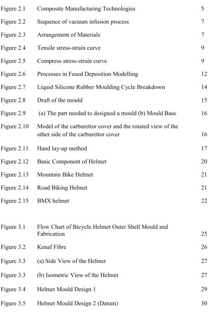
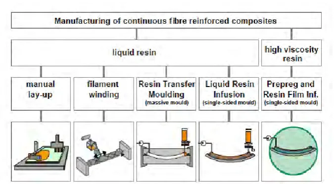
Figure 2.1 Composite Manufacturing Technologies 5 Figure 2.2 Sequence of vacuum infusion process 7
Figure 2.3 Arrangement of Materials 7
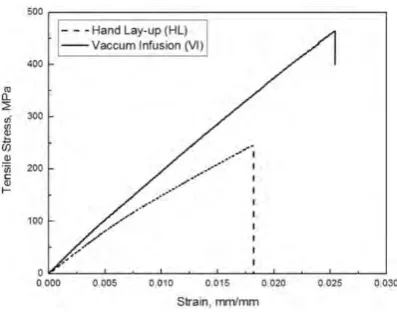
Figure 2.4 Tensile stress-strain curve 9 Figure 2.5 Compress stress-strain curve 9 Figure 2.6 Processes in Fused Deposition Modelling 12 Figure 2.7 Liquid Silicone Rubber Moulding Cycle Breakdown 14
Figure 2.8 Draft of the mould 15
Figure 2.9 (a) The part needed to designed a mould (b) Mould Base 16 Figure 2.10 Model of the carburettor cover and the rotated view of the
other side of the carburettor cover 16
Figure 2.11 Hand lay-up method 17
Figure 2.12 Basic Component of Helmet 20
Figure 2.13 Mountain Bike Helmet 21
Figure 2.14 Road Biking Helmet 21
Figure 2.15 BMX helmet 22
Figure 3.1 Flow Chart of Bicycle Helmet Outer Shell Mould and
Fabrication 25
Figure 3.2 Kenaf Fibre 26
[image:13.595.112.523.144.775.2]Figure 3.3 (a) Side View of the Helmet 27 Figure 3.3 (b) Isometric View of the Helmet 27
Figure 3.4 Helmet Mould Design 1 29
xi
Figure 3.6 Helmet Mould Design 3 30
Figure 3.7 Helmet Mould Design 4 30
Figure 3.8 Structural Analysis Option 34
Figure 3.9 Engineering Data Bar 34
Figure 3.10 Importing Geometry from SolidWorks ® File 35 Figure 3.11 Division of Bicycle Helmet for 3D Printing 36 Figure 3.12 The Orientation of Fibre Lay- Up inside the Mould 38
Figure 4.1 Bicycle Helmet Mould Drawing 40
Figure 4.2 (a) Normal Stress 42
Figure 4.2 (b) Shear Stress 42
Figure 4.3 Total Deformation 42
Figure 4.4 Shear Elastic Strain 43
Figure 4.5 Equivalent Elastic Strain 43
Figure 4.6 Safety Factor 44
Figure 4.7 Printed Helmet Section 45
[image:14.595.111.516.68.619.2]xii
LIST OF ABBREVIATIONS, SYMBOLS AND NOMENCLATURE
ABS - Acrylonitrile- Butadiene- Styrene A&E - Accident and Emergency
CNC -Computer Numerical Control FDM - Fused Deposition Modelling GFRP - glass-fibre reinforced plastic HL - Hand Lay-Up
LSR - Liquid Silicon Rubber
PMCs - Preformed Moulding Compounds PP - Polypropylene
POM - Polyoxmethylene SLA - Stereolithography SLS - Selective laser sintering STL - Standard Template Library UCS - Ultimate Compressive Strength UTS - Ultimate Tensile Strength VI -Vacuum Infusion
1
CHAPTER 1
INTRODUCTION
1.0 Background
Moulding process is crucial in manufacturing process in giving the desired shape of a work piece. A process of shaping liquid or pliable raw material using a rigid frame is known as mould or matrix with hollowed- out block (“What Is Moulding?” 2014). What defers mould from casting though both are the process shaping a specimen or product is that mould is a common term used for shaping plastics while casting is a common term used for metal shaping (Groover, 2007). They are several categories of moulding process according to Groove (2007). First is particulate process which involves the use metal powders and ceramics whereby these materials involves in the technique of pressing and sintering. Second is deformation process where the raw material is being shaped by the application of forces that exceed the material’s yield strength. Third is metal removal process. The operation in this process involves in removing the excess of the raw material from the starting work piece and formed it into desired shape. Lastly is surface processing where the operations of cleaning, surface treatment, coating and thin film deposition process take place.
2 emergency department visits due to bicycle injuries in 2013 according to Centre for Disease Control and Prevention (2016). There are three basic types of bicycle helmet. First is recreational helmets second is rode bike helmet and third is mountain bike helmet. These helmets usually use the in-mould type of construction where the outer shell and inner shell are fused without using any glue. This type of moulding results in light-yet-strong design.
1.1 Problem Statement
Acrylonitrile- Butadiene- Styrene (ABS) is a thermoplastic material that has been used widely in manufacturing world. Despite the versatility of this material in manufacturing world, there are drawbacks that lead to severe environmental defect. The environment is endangered by the melting process where hazardous gasses were emitted during injection moulding process. The melting plastic used for injection moulding also may be hazardous to the operator where there might be potentials of getting skin burns from contact with the heated barrel or from splattering hot plastic and gases or vapours (United States Department of Labour). The concern of the non-biodegradable material also is one of the major contributors to environmental hazard (Carr, 2016). Furthermore, photochemical oxidation contain in the plastic depleting the ozone layer (Elduque et al., 2015).The alternatives way available nowadays still using plastic based as material for the outer shell of the bicycle’s helmet. Mould of the outer shell of the bicycle is usually made out of metal which is complex and costly to fabricate. Also, the humidity effect during the processing phase where the humidity enters the system while the plastic is being made there will be uneven surface appearance of the moulded part and worst it is unusable (“Plastic Materials”, n.d).
3 by especially the recreational cyclist are only based on the appearance. The awareness on the benefits of wearing a good helmet amongst cyclist especially the recreational cyclist is still low. The education about how the good design and material of the outer most shell of the bicycle helmet is still at its bottommost level. Severe head injuries may leads to death without proper protection to prevent the occurrence.
1.2 Objectives
1. To design and fabricate moulding for bicycle helmet outermost shell 2. To analyse the mould design using computerize analysis
3. To fabricate the outermost shell of the bicycle helmet
1.3 Scope of Project
In order to achieve the objectives, several scopes have been determined:
1. Designing the moulding for bicycle helmet outermost shell by using Solidwork.
2. Analysing the mould using Ansys software analysis.
3. Fabricating the mould of the bicycle helmet using liquid silicone rubber. 4. Fabricating the outermost shell using hand lay-up with epoxy-resin and
4
CHAPTER 2
LITERATURE REVIEW
2.0 Introduction
Moulding is a very important component used to shape the product designed. The design for a product will need the aid of the computerized drawing software for higher precision and in-depth analysis on the mould designed to assure the defect that might occur during the product fabrication. Technique of fabrication should consider types of material that is being manufactured and the suitability of the chosen technique for the material to adapt with. Hand lay-up technique is a traditional technique in fabricating composite; however it is the most suitable technique that can be implied in making the outer shell of the helmet that is going to be reinforced with natural fiber.
2.1 Basics of Moulding
5 Figure 2.1 : Composite Manufacturing Technologies (Kleineberg, Herbeck and
Schöppinger, 2004)
2.1.1 Injection Moulding
6
2.1.2 Vacuum Infusion Moulding
UGent (2012) mention that there were many techniques to produce fiber that widely used nowadays. One of the techniques is Vacuum Infusion Process (VIP). This technique uses that vacuum pressure to drive resin into a cover. This procedure requires some assortment of supplies and materials. This technique had a few improvements implemented over traditional vacuum bagged parts. Thus, it provides much more advantages over the traditional method.
One of the advantages is this technique offers a better fiber-to-resin ratio than traditional vacuum bagging where it gives 1% in average of voids content (Swaylock’s Surfboard Design Forum, 2011). A typical hand lay-up usually results in excess of 100% fabric weight by resin. Although vacuum bagging could reduce this number significantly, the technique was considered as not ideal as it could lead to additional problems. Vacuum pressure remove a significant part of the resin, yet the amount removed still relies on a few factors such as reinforcement, resin, time factors, and others. Meanwhile, Vacuum infusion uses an alternate approach, in that a vacuum is drawn while the materials are still dry. After that, the resin is infused using vacuum pressure. Preferably, the vacuum line will eventually sucked out excess resin that is presented. Thus, just the base measure of resin is presented. This will help to lowers weight, increases strength, and maximizes the properties of fiber and resin. Besides that, this also gives less wasted resin produced during the procedure, and of course reduces waste of money. Reinforcing fibres are more oriented in any direction at specific and targeted locations.
7 There were no time limitations until it is concluded that the time has come to infuse the resin. Before that minute, any changes can be made repeatedly. The last benefit provides by vacuum infusion is it gives much cleaner process which is very preferable for bicycle helmet making that held indoor. There are no brushes or rollers used during the process that could result in splashing or spattering. Furthermore, there are less resins fumes to contend with. Because the only fumes radiate from the resin reservoir, they are to some degree containable. Vacuum infusion process gives a cleaner, more secure, and friendlier workplace, however it is still critical to work in a very much ventilated region and wear a respirator and other proper security gear.
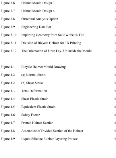
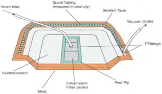
[image:22.595.188.446.381.490.2]Finish with the advantages, next is the process of resin infusion. The apparatus and equipment was set as we can see from the Figure 2.2. The arrangement of material in vacuum infusion process is illustrated in Figure 2.3.
Figure 2.2: Sequence of vacuum infusion process(UGent, 2012)
[image:22.595.183.456.560.719.2]8
2.1.3 Mechanical properties and production quality of hand-layup and
vacuum infusion materials
9 Figure 2.4:Tensile stress-strain curve (Sang-Young Kim et al., 2014)
Figure 2.5: Compress stress-strain curve (Sang-Young Kim et al., 2014)
Table 2.1: Average mechanical properties in tension (Kim et al., 2014) Hand Lay-up Vacuum Infusion
Batch 1 Batch 2 Batch 3 Batch 1 Batch 2 Batch 3 Ultimate
strength(MPa)
[image:24.595.154.561.535.643.2]