UNIVERSITI TEKNIKAL MALAYSIA MELAKA
PERFORMANCE ANALYSIS OF 1HP SPLIT TYPE ROOM AIR
CONDITIONER USING REFRIGERANT R410A AND R32
This report is submitted in accordance with the requirement of the Universiti Teknikal Malaysia Melaka (UTeM) for the Bachelor of Mechanical Engineering
Technology (Refrigeration and Air-Conditioning Systems) with Honours.
by
TAN REN JIE B071410263 940713-10-5129
i
DECLARATION
I hereby, declared this report entitle
PERFORMANCE ANALYSIS OF 1HP SPLIT TYPE ROOM AIR CONDITIONER USING REFRIGERANT R410A AND R32
is the results of my own research except as cited in references.
SIGNATURE :
AUTHOR’S NAME : TAN REN JIE
ii
APPROVAL
This report is submitted to the Faculty of Engineering Technology of UTeM as a partial fulfilment of the requirements of the degree Bachelor of Mechanical Engineering Technology (Refrigeration and Air-Conditioning Systems) with Honours. The member of the supervisory is as follow.
iii
ABSTRAK
iv
ABSTRACT
v
DEDICATION
vi
ACKNOWLEDGEMENT
Foremost, I would like to express my sincere gratitude and appreciation to my supervisor Mdm. Siti Nor’Ain Binti Mokhtar for the continuous support, patience, motivation and enthusiasm throughout this research dissertation. The door to my supervisor was always open whenever I ran into a trouble or had a question about my research or writing.
Besides my supervisor, I would also like to take this opportunity to express my very profound gratitude to my friends who have always supported me throughout the process. They have guided me, helped me and motivated me during the last four years. I will always appreciate all they have done.
Finally, I also place n record, my sense of gratitude to one and all, who directed or indirectly have lent their hand in this Final Year Project.
vii
TABLE OF CONTENT
Declaration i
Approval ii
Abstrak iii
Abstract iv
Dedication v
Acknowledgement vi
Table of Content vii
List of Tables x
List of Figures xi
List of Abbreviations, Symbols and Nomenclature xii
CHAPTER 1: INTRODUCTION 1
1.1 Problem Statement 2
1.2 Objectives 3
1.3 Scope 3
1.4 Organization 3
CHAPTER 2: LITERATURE REVIEW 5
2.1 Operation of Air Conditioning System 5
2.1.1 Vapour Compression Cycle 6
2.2 Classification of Air Conditioning System 7
2.2.1 Individual Systems 8
2.2.2 Unitary Packaged Systems 8
2.2.3 Centralized Systems 9
2.3 Type of Individual Systems 10
2.3.1 Split Air Conditioning System 10
2.3.2 Windows Air Conditioning System 11
2.3.3 Portable Air Conditioning System 11
2.4 Refrigerant 12
viii
2.4.2 R32 14
2.4.3 Comparison of R410A and R32 15
2.5 Global Warming Potential (GWP) 17
2.6 Coefficient of Performance (COP) 19
2.7 Mollier Diagram (Mollier Chart) 19
2.8 Conclusion 21
CHAPTER 3: METHODOLOGY 22
3.1 Methodology Flowchart 22
3.2 Experimental Research 23
3.2.1 Specifications of Both Tested Air Conditioners 24
3.2.2 Experimental Venue 24
3.3 Research Instrument 26
3.3.1 Digital Thermometer 26
3.3.2 Manifold Gauges 27
3.3.3 Power Quality and Energy Analyzer 27
3.4 Experimental Planning 28
3.5 Data Analysis Technique 29
3.6 Conclusion 29
CHAPTER 4: RESULTS AND DISCUSSION 30
4.1 Methods of Data Collection 30
4.1.1 Temperatures 30
4.1.2 Suction and Discharge Pressures 32
4.1.3 Mollier Chart (Pressure-enthalpy Diagram) 32
4.1.4 Power, Voltages, and Currents 34
4.2 Coefficient of Performance (COP) 35
4.3 Supply Voltage, Running Current and Power Analysis 38
4.3.1 Supply Voltage (V) 38
4.3.2 Running Current (A) 39
4.3.3 Power Consumption (W) 41
4.3.4 Annual Power Consumption (kWh) 43
ix
CHAPTER 5: CONCLUSION AND RECOMMENDATION 45
5.1 Summary of Results 45
5.2 Achievement of Objectives 47
5.3 Exceptions and Limitations 47
5.4 Recommendation 49
REFERENCES 50
x
LIST OF TABLES
2.1 Refrigerant safety grouping in ASHRAE Standard 34-22013 14 2.2 Basic properties of R410A and R32 (AHRI Standard 700, 2015) 15
3.1 Specifications of both tested split type air conditioners 24
4.1 Temperatures, pressures and COP for air conditioning using R410A. 36 4.2 Temperatures, pressures and COP for air conditioning using R32. 37 4.3 The average supply voltages of both air conditioner. 39 4.4 The average running current of both air conditioner. 41 4.5 The power consumption of air conditioner using R410A. 42 4.6 The power consumption of air conditioner using R32. 42 4.7 Annual power consumption of both air conditioner. 43 4.8 Manufacturer claims and experimental results for unit R410A. 44 4.9 Manufacturer claims and experimental results for unit R32. 44
xi
LIST OF FIGURES
2.1 Vapour Compression Cycle 6
2.2 Example of unitary packages system 8
2.3 Example of centralized unit 9
2.4 Example of wall mounted split air conditioner 10
2.5 Example of window air conditioner 11
2.6 Example of portable air conditioner 12
2.7 Comparison of R410A and R32 P-h diagram 16
2.8 Calculating COP using Mollier diagram 20
3.1 Methodology flowchart 23
3.2 The layout of HVAC Technology Industry Lab 25
3.3 The illustration of equipment setup 25
3.4 Fluke 52-2 Dual Input Digital Thermometer 26
3.5 Manifold gauges for R410A and R32 27
3.6 Fluke 435 Series II Power Quality and Energy Analyzer 28 3.7 Interface of TechniSolve MollierChart software 29
4.1 The statistic of supply voltage. 38
4.2 The summary information of supply voltage. 39
4.3 The statistic of running current. 40
4.4 The summary information of running current. 40 4.5 Graph of Power against Current (constant voltage) 42
xii
LIST OF ABBREVIATIONS, SYMBOLS AND
NOMENCLATURE
AHU - Air Handling Unit
ASHRAE - American Society of Heating, Refrigerating and Air Conditioning Engineers
CCWS - Central Chilled Water System CFCs - Chlorofluorocarbons
COP - Coefficient of Performance DX - Direct Expansion
GWP - Global Warming Potential HCFCs - Hydrochlorofluorocarbons HFCs - Hydrofluorocarbons
HP - Horsepower
HVAC - Heating, Ventilating, and Air Conditioning
HVAC &R - Heating, Ventilating, Air Conditioning and Refrigerating NASA - National Aeronautics and Space Administration
ODP - Ozone Depletion Potential PAC - Portable Air Conditioner WHO - World Health Organization
̊ C - Degree Celsius
̊ F - Degree Fahrenheit
1
CHAPTER 1
INTRODUCTION
1.0 Background
Air conditioning is defined as a system for treating air in buildings, etc., so as to maintain those conditions of temperature, humidity, and purity best adapted to personal comfort, etc. (Funk & Wagnalls Inc., 1980). Air conditioning is use to alter and maintain an indoor air temperature at a specific temperature regardless the time or season of a country. The goal of air conditioning is to provide a more comfortable interior environment compared to the exterior environment or outdoor typically for human and animal.
On July 17, 1902, the first modern air conditioning system was invented by a 25 years old engineer named Willis Carrier from New York. At that time, Carrier is tasked to find a solution for the production problem at the Sackett & Wilhelms Lithography and Printing Company in Brooklyn, New York. The problem began with the paper affected by excessive humidity in the printing company where the paper stock was expanding and contracting during printing and caused misaligned, poor quality and waste production days. By 1903, Carrier designed a system of chiller coils to maintain a constant and comfortable humidity of 55% year-round to Sackett & Wilhelms printing plant. The modern air conditioning was born. (Weathermakers of The World, n.d.)
2 the global warming or greenhouse effect caused by the emissions of fluorine such as HFCs and HCFCs contained in refrigerant through venting and leakages of refrigerant. Qing (2013) from University of Waterloo argues that chlorofluorocarbon (CFCs) is to be blame for global warming since 1970s and not carbon dioxide (𝐶𝑂2) according to
a published by International Journal of Modern Physics B. In addition, the operation of air conditioner consumes a large amount of electricity generated mostly by burning fossil fuels and as such makes contribution to the global warming and air pollution due to the additional of carbon emissions.
Refrigerant R410A has been widely used in air conditioning system for the past decade in Malaysia, especially in split type air conditioner. R410A is a non-ozone depleting refrigerant as it has zero (0) ozone depletion potential (ODP), however it has significant global warming potential (GWP) of 2088. The high GWP of R410A has been concerned as it attributed to the global warming. As a result, refrigerant R32 is used to replace R410A as they both have some similar properties and characteristics. R32 has zero (0) ODP and a relatively low GWP of 675, which is 1413 or equivalent to 68% lesser than R410A.
1.1 Problem Statement
3 current R410A refrigerant to ensure it is not only has low GWP but crown in its overall performances including energy efficiency, cost effectiveness, safety and other factors.
1.2 Objectives
The objective in this project is to collate the operating conditions including the energy consumption, temperatures and pressures of both split type air conditioner using two different types of refrigerant which is R410A and R32 under standard conditions. Besides that, the coefficient of performance (COP) of both split air conditioners using two different refrigerants (R410A and R32) is to be determined.
1.3 Scope
Refrigerant are widely used in a variety of heating, ventilating, air conditioning and refrigeration (HVAC&R) equipment. However in this report, I will only focus primarily on the cooling performance of both 1HP (horsepower) domestic split type room air conditioners (wall mounted) which equipped with two different types of refrigerant R410A and R32. Parameters like temperatures, both discharge and suction pressures, energy consumption and coefficient of performance (COP) of the both the air conditioning units are to be determined. A minimum running time of an hour of the system is necessary to ensure the operation is stable before any data collected.
1.4 Organization
5
CHAPTER 2
LITERATURE REVIEW
2.0 Introduction
Chapter Two – Literature Review discussed about the published information in particular related to the topic of research involved in this study. As defined by Concordia University, literature review is a “written overview of major writings and other sources on a selected topic. Sources covered in the review may include scholarly journal articles, book, government reports, Web sites, etc. The literature review provides a description, summary and evaluation of each source”. This chapter is done based on scholarly articles, journals, books and online sources which relevant to the field of study. The purpose of this chapter is to offer an overview of the significant literature published from various sources which relevant and similar to the research to support the topic.
2.1 Operation of Air Conditioning System
6
2.1.1 Vapour Compression Cycle
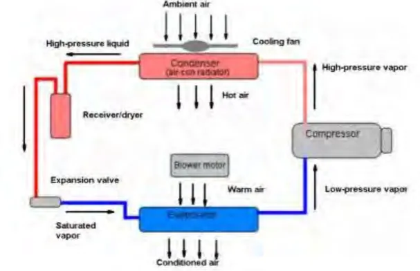
[image:19.595.185.489.293.489.2]Cooling or refrigeration is a process of moving heat (thermal energy) from a colder region to a warmer region. Refrigeration system is a combination of interconnected refrigerant containing devices in which the refrigerant is circulated for the purpose of extracting heat to produce cooling (Gupton, G. W., 2002). The most common or widely used method of cooling is vapour compression cycles. Vapour compression cycles uses four main components of the air conditioning system (compressor, condenser, expansion valve and evaporator) to produce cooling effect.
Figure 2.1: Vapour Compression Cycle
7 liquid refrigerant is restricted and causes a pressure drop at the exit of the valve. This drastically drop in pressure causes the temperature of the refrigerant drops to an extremely cool temperature. The low pressure and low temperature liquid refrigerant is then entered to the evaporator. The blower will force the air in the conditioned space across the evaporator coil, heat transfer happens where the heat in the air transferred into the refrigerant. The liquid refrigerant boils or evaporates to “saturated vapour” in the evaporator as it absorbs heat from the surrounding air. The low pressure vapour refrigerant is then return to the compressor and the cycle is repeated.
Heating is a process of supplying heat to a room or building by a system used to do so (Oxford Dictionary, 2010). A heating system provides warmth or thermal comfort through supplying heat from a heat source to a conditioned space. In four season countries, heating devices is very important as an air conditioning system to provide thermal comfort in a room or building from freezing cold weather during winter. Vapour compression cycle can produce heating too other than just cooling. By reversing the flow of refrigerant in the vapour compression cycle, it can produce heating to the conditioned space. A reversing valve can be switched to change from cooling to heating or vice versa claimed by Weston (1992). This allows cooling and heating to achieve in a single system.
2.2 Classification of Air Conditioning System
8
2.2.1 Individual Systems
An individual air conditioning system usually utilize either a single, self-contained (assembled by factory and ready to use), packaged room air conditioner (window air conditioner) or separated indoor and outdoor units (split air conditioner) often used to condition an individual room. (Wang & Lavan, 1999). Individual system is small in size, easy to install, and the control is simple for individual room. However, individual system only can serve a limited space or a small area.
2.2.2 Unitary Packaged Systems
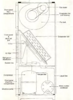
[image:21.595.276.397.569.734.2]In package air conditioning system, the compressor, evaporator, blower and air filter are all fitted in one single cabinet and assembled at the factory location. It is usually is placed on a roof or on a concrete slab next to the house's foundation. This type of air conditioner is used in small commercial buildings. The conditioned air is normally transferred though ducting which is usually hidden in the ceiling or wall of the building. Air supply and return ducts come from indoors through the home's exterior wall or roof to connect with the packaged air conditioner, which is usually located outdoors. Unitary packages system can divide into two types, one with air cooled condenser and one with water cooled condenser depends to the capacity required and spatial availability.
9
2.2.3 Centralized Systems
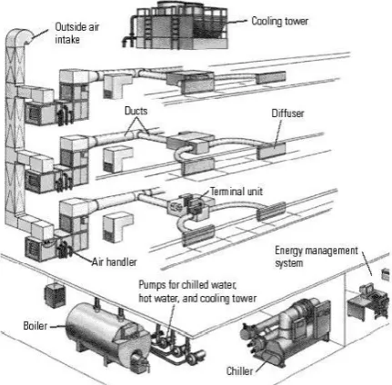
[image:22.595.229.445.372.584.2]Centralized air conditioning systems are used when large buildings comprising of several floors such as hotels, theatres, airports and shopping malls are to be air conditioned completely. There are two type of cooling method in centralized system, direct expansion (DX) and using central chilled water system (CCWS). In direct expansion system, refrigerant is directly used to cool the conditioned room air, whereas in chilled water system the refrigerant first chills the water, which in turn chills the room air. In central chilled water system, the water is chilled to very low temperature by the chiller. The chilled water is then pumped to the Air Handling Unit (AHU), the chilled water will absorb the heat from the conditioned space through the return air forced across the evaporator coil by a blower in the AHU. The conditioned air is then flow to the entire building via ducts.
10
2.3 Type of Individual Systems
2.3.1 Split Air Conditioning System
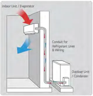
[image:23.595.257.417.552.716.2]Split air conditioner is popular for their high-efficiency cooling performance. It is comprises of two basic parts, the indoor unit and outdoor unit. The indoor unit, fitted inside the room or house, comprises the evaporator or cooling coil and the blower. The outdoor unit, fitted outside the room (outdoor) or house, comprises the compressor, condenser and expansion valve. Split air conditioners typically found in residential or small commercial buildings which can be wall mounted, ceiling mounted and floor mounted. Airedale Cooling Services Ltd (2015) posted a finding of difference between wall mounted and floor mounted air conditioning, wall and ceiling mounted split air conditioner normally takes longer time for occupant to feel the benefit. However, it will provide a good distribution of conditioned air throughout the space as cool air will eventually move downwards (denser) and warm air will rise upwards (less dense). On the other hand, floor mounted split air conditioner is at ground level, it takes less time for occupant to feel the benefit as occupant is closer proximity to it. Floor mounted is usually used when there is an architectural constrain where no solid wall available for appliances attachment. Example of drawback is furniture will cause blockage of air flow from distribute evenly throughout the space.
11
2.3.2 Windows Air Conditioning System
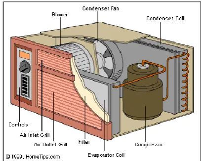
[image:24.595.235.441.409.572.2]Window air conditioners or sometimes known as room air conditioner are one of the most commonly used and cheapest types of air conditioners. All the components like the compressor, condenser, expansion valve and evaporator coil are assembled in a single casing. According to airconditioning-system.com (2011), this type of air conditioner has a double fan shaft motor with fan blades mounted on both end of the motor shaft. One fan blade is located at the condenser side, while the other one is located at the evaporator side. There is an insulated partition used to separate both of the condenser and evaporator within the same casing. It is typically installed in a window or custom opening in a wall. Window air conditioner units are reliable and simple to install to keep a room cool while avoiding costly construction. However, this system can only cool small areas and are not intended to provide cooling to multiple rooms or zones. In addition, window air conditioner units can be easily removed for storage when the summer heat dies down.
Figure 2.5: Example of window air conditioner
2.3.3 Portable Air Conditioning System