COMPUTER PROGRAMMING SERIES
DIGITAL
COMPUTER GRAPHICS
VOL. I
PUBLISHED BY
AMERICAN DATA PROCESSING, INC.
©Copyright by American Data Processing, Inc.
PREPARED UNDER CONTRACT NO. NAS 8-21227 By LOCKHEED MISSILES & SPACE COMPANY,
ABSTRACT
This document represents a study of data collection, application analysis, and user
requirements for the following five computer graphics applications:
• Numerical Control
• Electrical Network Analysis
• Flight Mechanics • Structural Analysis
• Engineering Drawing Retrieval
A discussion of "study of Man-Machine Solution Optimization" and a hardware analysis
report of the MSFC Univac 1108 computer complex using Univac specifications are
also presented.
The results of 'a Computer-Aided Design/Computer Graphics literatu~e search is
compiled into an annotated bibliography as Volume II of this report. Conclusions and
recommendations in respect to computer graphics and the various areas of computer
graphic applications are summarized.
This study was prepared by Lockheed Missiles & Space Company under COJ;1tract
ACKNOWLEDGMENTS
The following LMSC personnel made major contributions to this document:
P. W. Card
D. L. Drew
W. R. Dunn
S. Elster
S. K. Ferriera
K. R. Gielow
J. F. Golden
F. S. Kessler
M. A. Krop D. C. Miller
R. L. Moll N. E. Nielson
W. C. Randels
C. J. Skogh P. L. Taulbee
D. L. Trask
Significant contributions were also provided by D. A. Biederman of Lockheed
CONTENTS
Section Page
ABSTRACT iii
ACKNOWLEDGMENTS iv
ILLUSTRATIONS ix
TABLES xiii
INTRODUCTION xv
1 NUMERICAL CONTROL 1-1
1.1 Numerical Control (N/C) and Computer Graphics
Involvement in the" II.ldustrial Process 1-2
1.2 F~asibility of N/C - Computer Graphics at MSFC 1-16
1.3 Numerical Control and N / C - Computer Graphics
Specifications 1-20
2 ELECTRICAL NETWORK ANALYSIS . 2-1
2.1 Summary 2-2
2.2 Network Analysis Program Requirements for the
Graphics System 2-2
2.3 Description of Available Network Analysis Programs 2-4
2.4 Program Evaluation 2-11
2.5 Program Selection 2-13
2.6 Program Modifications 2-13
2.7 User Graphic Procedures 2-15
2.8 Network Analysis Graphics Applications at Lockheed 2-21
2.9 Network Analysis Graphics Applications at Other
Section Page
2.10 Programming Requirements 2-23
3 FLIGHT MECHANICS 3-1
3.1 Mode of Application of Graphics 3-1
3.2 Graphical-Computer System for Orbital Transfer
Studies 3-4
3.3 Requirements Specification for Orbital Transfer
Studies 3-15
3.4 Graphical-Computer System for Ascent Boost
Optimization. 3-29
3.5 Requirements Specification for Ascent Boost
Optimization 3-50 .
3.6 Conclus ions and Recommendations 3-55
3.7 References 3-56
4 STRUCTURAL DESIGN ANALYSIS 4-1
4.1 Background 4-1
4.2 Introduction to Specifications 4-17
4.3 Program Requirement Specifications 4-19
4.4 Hardware/Software Requirements 4-32
4.5 Program Specifications 4-32
4.6 PEANUTS: An Example of Graphic Program
Require-ments and Specifications 4-70
4.7 References 4-87
5 ENGINEERING DOCUMENT RETRIEVAL 5-1
5.1 Introduction 5-1
5.2 System Requirements 5-2
5.3 Storage and Retrieval Systems 5-20
5.4 Recommendation 5-37
5.5 Hardware State-of-the-Art 5-78
Section Page
6 STUDY OF MAN/MACHINE SOLUTION OPTIMIZATION 6-1
6.1 Introduction 6-1
6.2 Description of Program 6-2
6.3 Experiment Data and Operations 6-4
6.4 Instructions 6-22
6.5 Suggestions for More Efficient Division of Labor
Between Man and Computer 6-23
6.6 Simulation 6-24
7 HARDWARE ANALYSIS 7-1
7.1 Introduction 7-1
7.2 Hardware System Configuration 7-1
7.3 Software System 7-3
7.4 Display Operations 7-4
7.5 Conversion Considerations 7-6
ILLUSTRATIONS
Figure Page
1-1 Symbols Defined 1-38
1-2 Subroutine START 1-39
1-3 Subroutine POINT 1-40
1-4 Subroutine LINE--POINT-TO-POINT 1-41
1-5 Subroutine LINE-POINT. DIRECTION -1-42
1-6 Subroutine CIRCLE 1-43
1-7 Subroutine PARALLEL 1-44
1-8 Subroutine FILLE T 1-45
1-9 Subroutine RETOUCH 1-46
1-10 Subroutine LINE TYPE 1-47
1-11 Subroutine TRANS FORMA TION 1-48
1-12 Subroutine NUMERICAL CONTROL 1-49
1-13 Subroutine DIMENSIONING 1-51
1-14 Subroutine MACRO - 1-52
1-15 Local Area Layout of Display-Oriented Support Equipment 1-82
2-1 Typical Component Templates 2-17
2-2 Completed Schematic 2-18
2-3 Proposed Control Surface Layout 2-24
2-4 Proposed Keyboard Layout 2-26
2-5 Sample Component Group Structure ·2-32
3-1 Orbital Transfer Display Scope 3-9
3-2 Ascent Boost Optimization REVIEW Display 3-39
3-3 Ascent Boost Optimization MONITOR Display 3-45
4-1 ,PEANUTS - Structural Design Evolut~on- 4-12
Figure Page
4-3 Rectangular Communicat~on and Data Display Layout 4-28
4-4 Square Communication and Data Display Layout 4-28
4-5 Shifted Square Communication and Data Display Layout 4-29
4-6 Communication Message Area Layout 4-29
4-7 Frame Types 4-31
4-8 Application Data Base Structure 4-34
4-9 Data Base Access Program 4-35
4-10 Resident Name Table (RNT) 4-37
4-11 Program ID Table (PIDT) 4-38
4-12 Case ID Table (CIDT) 4-39
4-13 Data Requirement Table (DRT) 4-40
4-14 Program Data Reference Table (PDRT) 4-42
4-15 Sample Data Set Format 4-43·
4-16 Library Program 4-45
4-17 Sign-on Program 4-46
4-18 Stop ProgIam 4-47
4-19 Program Selection Program 4-49
4-20 Program Next Case 4-50
4-21 Input-Output Flow for Card, Magnetic Tape and Data Base 4-51
4-22 Input Data Flow for Cathode-Ray Tube 4-52
4-23 Input Program 4-53
4-24 Card Input Program 4-55
4-25 Tape Input Program 4-56
4-26 Data Base Input Program 4-57
4-27 CRT Input Program 4-58
4-28 Compute Program 4-61
4-29 Standard Output Program 4-63
4-30 General Output Program 4-64
4-31 Void Output Data Program 4-65
Figure Page
4-33 Functional Block Diagram of an Ideal Structural Program 4-71
4-34 Functional Block Diagram of PEANUTS 4-72
4-35 Function Input 4-81
4-36· Single Item Input 4-82
4-37 Standard Output Display 4-86
5-1 Documentation Repository Input 5-7
5-2 Engineering Documentation Released by MSFC Release Center
and Forwarded to Central Repository 5-8
5-3 Documentation Repository Output 5-14
5-4 Program Distribution of Manpower at MSFC 5-17
5-5 AAP Documentation Processed by MSFC Engineering Release
Center Between June and December 1967 5-19
5-6 Documentation Flow 5-21
5-7 Sample of MSFC Form. 2896 - Document Input Record 5-27
5-8 Sample of MSFC Form 433 - Request for Documentation 5-28
5-9 Sample of MSFC Form 2598 - Distribution Data Acquisition List 5-29
5-10 Release and Accounting Procedure Flow 5-31
5-11 Saturn SA-5 Main Assemblies 5-43
5-12 Breakdown of Saturn SA-5 Payload and Stage I Assemblies 5-45
5-13 Logical Flow Chart Segments SL1, SL2 ·5-56
5-14 Logical Flow Chart, Segment S 5-58
5-15 Logical Flow Chart, Segment D 5-60
5-16 Logical Flow Chart, Segment E 5-61
5-17 Logical Flow Chart, Segment U 5-63
5-18 Logical Flow Chart, Segment I 5-64
5-19 Logical Flow Chart, Segment A 5-66
5-20 Logical Flow Chart, Segment DL 5-68
5-21 Logical Flow Chart, Segment R 5-70
5-22 Logical .Flow Chart, Segment IN 5-72
5-23 Typical Display - Interface Structure 5-73
Figure Page
5-25 Typical Display - Structure Breakdown 5-75
6-1 Flow Diagram Used for the 144 Experiment 6-3
6-2 Complete Data Display 6-6
6-3 Display of Data Before Acceptance Into Data Set 6-7
6-4 Display of Functions of 10 Best Curves 6-8
6-5 Display of Best Curve 6-9
6-6 Display for User to Select a Function, Transform and Degree 6-12
6-7 Display of Chosen Curve From Box I, Fig. 6-1 6-13
6-8 Run 1, 144 Curve Fit Program, Preplot and Curve 6-16
6-9 Run 1, Computer Output 6-17
6-10 Run 2, 144 Curve Fit Program 6-18
6-11 Run 2, Computer Output 6-19
6-12 Run 3, 144 Curve Fit Program" Preplot and Curve 6-20
6-13 Run 3, Computer Output 6-21
7-1 Hardware Configuration 7-2
7-2 Display Console With Permanent and Programmed Controls
Table 1-1 1-2 1-3 1-4 1-5 1-6 1-7 1-8 1-9 1-10 1-11 1-12 1-13 1-14 2-1 2-2 3-1 3-2 3-3 3-4 4-1 4-2 4-3 4-4 4-5 TABLES
Console Procedures for Start (Keyboard Oriented)
Console Procedures for Numerical Control
Console Procedures for Erase
Console Procedures for Line Type
Console Procedures for Fillet
Console Procedures for Retouch
Console Procedures for Parallel
Console Procedures for Circle
Console Procedure s for Point
Console" Procedures for Line Through Point at Direction
Console Procedures for Line Point to Point
Console Procedures for Dimensioning Information
Console Procedures for Geometry Macro
Console Procedures for Transformation
Network Analysis Program~
Network Analysis Program Evaluation for Graphics
Sample Output of Orbital Transfer Program
Timing and Storage Requirements for Orbital Transfer System
Light Button Actions for Orbital Transfer System
Storage and Timing Requirements for Ascent Boost Optimization
Representative Listing of Structural Analysis Computer Programs
List of Input Requirements
Command Table
Register Table
Description of Input Quantities
Table
4-6
5-1
5-2
5-3
6-1
7-1
List of Possible Output From PEANUTS Summary of R&D and 10 Usage
Six Most Active Requestors - October 1967
Machine Readable Documents
Time Elements
Hardware Comparison - CDC 273 vs. Univac Mariner Display
Page
4-79
5-13 5-15
5-77
6-11
INTRODUCTION
This country's scientific and technical environment increases in proportion to the de-sign and complexity of our space program hardware. The resulting data which
repre-sent research, development, and design effort have become less accessible because of
the sheer mass of informati9n that must be stored, manipulated and retrieved. As a
result, the data originator is literally separated from the information he needs and the
cleavage increases as the data collection grows.
With the advent of on-line techniques and direct access devices the problem is
dimin-ished, but only in a limited manner in the area of alphanumerics, i. e., the advisability
of using on-line devices to examine mathematical equations -is questionable when the
changed data output must be transferred to hard copy and compared against graphic
representations. This is a time-consuming i~erative process. Graphics computer
in-put devices that allow this iterative process on-line in an interactive', 'real-time mode
are the keys to meaningful use of the computer as a tool to support the originators of
information. Data capture at its initiating source rather than at th~ first paper ~is
closure as is presently inferred by the term "source data" is a prime goal in computer
graphics. Some of the same benefits 'and advantages which are only promised in non-graphic, computer-aided design can actually be realized with the addition of graphics.
These benefits include:
• Ability to observe the results in graphic form without having to resort to
hard copy output
• Immediate program interaction capability
• Ability to revise data directly without a manual data reduction step by
allow-ing users to work with problems in the graphics environment
• Ability to drive other output devices directly and produce hard copy or
Computer graphics at Lockheed has been conducted primarily on Lockheed independent
development funds. While Lockheed interest in computer graphics dates back to 1958,
the p~esent operation, which began in 1962 at LMSC, is an outgrowth of an attempt to
improve the design effort through computer graphics utilization.
Most of the early effort was concentrated on system evaluation and use of a printed
circuit design program as the first application of software. Subsequent efforts have
included such applications as reentry vehicle deSign, logic design, structural dynamics,
and trajectory analysis.
Lockheed-Georgia Company and Lockheed-California Company have been actively
en-gaged in this area on both independent and joint cooperative ventures within LAC.
Lock-heed Electronics Company (LEC) is examining applications presently relative to entry
into graphics. Lockheed-Georgia Company ~as research-oriented applications in
pro-gress, both in computer-aided design and in computer graphics. The computer graphics
programs include structural analysis, electrical circuit layout, and numerical control
center path development for the operation of numerically controlled machine tools. At
present, parts are being fabricated for the C5A program from input.using a computer
graphic terminal. Applications have been developed for both aircraft and shipbuilding
operations. Lockheed-California Company has four major areas of computer graphics
applications: design, design analysis, flight test, and numerical control of machine tools.
This report is segregated into eight major areas:
• Five computer graphic applications (see below), discussion of data collection
and the application analysis, and a statement of user requirements ( a
require-ments specification) for each application:
1. Numerical Control
2. Electrical Network Analysis
3. Flight Mechanics
4. Structures Analysis
o A "discussion of "Study of Man.,..Machine Solution Optimization"
• A hardware analysis report of the MSFC Univac 1108 computer complex in
MSFC Computation Laboratory taken from the Univac specifications supplied
to LMSC especially for this study
e An LMSC Computer-Aided Design/Computer Graphics literature search bound
separately as Volume II of this report
Each of the five computer graphic applications contains terms which are common to all
along with special terms peculiar to the application. These are grouped together as a
glossary for the total report in the appendix.
When applicable there is a summary of conclusions and recommendations, in each of
the applications described herein.
The computer graphic hardware referred to in this report (and upon which all program applications are based) need not be of any specific manufacture or type, but generally
consists of, as a minimum:
• A basic computing machinery (mainframe)
• A cathode-ray tube with a light-sensitive probe (light pen or pencil) with which
the user points at the CRT and manipulates graphic lines o;r alphanumeric data
plus certain auxiliary input devices such as a "button box" or keyboard (both
of which mayor may not be capable of input of alphanumerics or special
graphic symbols and commands)
• Peripheral hardware for input and output such as a card punch, card readers,
high speed printers, collators, sorters, tape drivers, etc.
The main consideration in all of the following is that the least complex hardware array
allows the user/operator direct interaction with his program which is available as a
Section 1
NUMERICAL CONTROL
This section covers a portion of NASA-MSFC study contract NAS 8-21227. With
dele-tions specified during negotiadele-tions, it is responsive as described in the LMSC proposal
No. 699516, dated February, 1967.
The firms from which information for this study was gathered are:
o General Electric Industrial Process Control Division
G Gerber Scientific Instrument Company
o International Business Machines Corporation
o Lockheed Georgia Company
o Lockheed California Company
o Sundstrand ·Machine Tool Division of Sundstrand Corporation
o Bendix Industrial Controls Division
o Cincinnati Milling Machine Company
o Control Data Corporation
o Pratt & Whitney Machine Tool Division
• McDonnell - Douglas Aircraft Corporation
'" Bunker Ramo Woolridge Company
• TRW, Incorporated
• Boeing Aircraft Company
• Kearney and Trecker·
• Universal Drafting Machine Company
Society affiliations employed in this effort include the following:
• Aerospace Industrial Association
• Society of Automotive Engineers
• American Ordnance Association
Another source of information was the illinois Institute of Technology - Research. Institute.
This document is intended to be comprehensive enough to facilitate successful
imple-mentation of Computer Graphics - Computer Aided Design - Numerical Control as one
system when combined with an appropriate operating community and compatible hard-ware and software~
It should be recognized that some of the detailed information contained herein is in a
state of change or expansion. The authors have attempted to provide enough
informa-tion to enable creainforma-tion of a working system, but they could not hope to foresee all future refinements.
1.1 NUMERICAL CONTROL (N/C) AND COMPUTER GRAPHICS INVOLVEMENT IN THE INDUSTRIAL PROCESSES
1.1.1 General Discussion
Numerically controlled machining, processing, and testing devices have become so
sophisticated that many users now enjoy a high degree of precision. Also, the
inter-facing of computing equipment and computer graphic presentations to the N/ C
func-tion allows man to develop a concept, review it, analyze it, modify it, and construct
the manufacturing tool in a completely dynamic environment. It is also significant
that, in addition to X-Y plotting eqUipment, another aid to man-machine co~munica
tion is computer-interfacing, precision line drawing equipment, which enables a
comfortable documentation transition period and completes the total industrial proces s.
The techniques of the use of computer graphics by the engineering community is the
subject of a narrower field of study because of the many varying needs for data
manip-ulation. However, the greatest realization of the potentials offered by computer
graphics and numerical control will come from an industrial process that essentially
eliminates dependency upon man for any interpretive roles beyond design completion
potential depends on the possession by the design engineer/operator of a complete understanding of the computer graphic environment. Only a few design engineers are
now taking advantage of the existing new capabilities offered by data automation and
computer graphic systems. It is therefore important that manufacturing and engi-neering personnel receive complete orientation in the latest disciplines.
A unique capability· becomes available with use of the CRT and light pen for design
engineering communication with the computer, and use of the same CRT and light
pen for N/C parts programming, coupled with non-interpretive use of N/C graphics
equipment, alphanumeric printers, punched tape, film, magnetics, electrostatics,
etc. , for documentation of any or all results.
One of the objectives of this study is to arrive. at ~pecifications which enable
establish-ment of a working system to accomplish these, ends. Existing technology pr.ovides the
capability for implementing all the aforementioned technologies into one integrated system. It is improbable, under the present Engineering and Manufacturing
organi-zational structure in the industry, that the cost-effectivenes s of numerical control can
be fully demon~trated. Consequently, a c~nsiderable amount of the computer
graphics-engineering-N/C portion of this total NASA-MSFCstudy is devoted to the involvement
in the industrial processes and to answering such questions as the following:
o What are the optimum techniques for training personnel in the use of these
computer-aided capabilities? .
• What organizational structures offer optimum realization of the potentials of these new technologies?
• What are the most advantageous approaches to linking together the computer,
the N/ C control system, and the N/ C tool?
• What techniques for introduction of the computer-aided capabilities into the
engineering/manufacturing/operational communities offer the greatest
potential for early acceptance and use?
• What growth potential is necessary?
• What new computer-aided design techniques will be developed in the next
three to five years?
• What is the value/need of software interchangeability between various
facilities?
• What is the opportunity to take advantage of the economies offered by use
of existing software?
1. 1. 2 Answers to Questions Previously Posed
Each of the previously listed questions will be dealt with in the following. Information
has been gathered through visits and conferences with members of the industry, through
searching literature, and through personal research.
1.1. 2.1 ~at are the Optimum Techniques for Training Personnel in the Use of These
Computer-Aided Capabilities? Initially, those who need training must be identified;
and the extent to which they will be trained must be agreed upon. Th~n the varieties
of techniques can be evaluated to determine which offers the highest potential for
success.
The degree of success of employment of a CG-CAD-N/C (Computer Graphics - Compll:ter
Aided Design-Numerical Control) system will be in direct proportion to the degree of
accurate knowledge of the system held by: (a) manufacturing, (b) engineering, and
(c) management. The weakest of the three will be the limiting factor for full
realiza-tion of the potentials of the CG-CAD-N/C system. The technique of training each
group will be different, and yet the over lap of understanding must" be broad.
a. The N/C manufacturing community (even more than the conventional) could
much more easily and accurately program the creation of a part if the
designers limited themselves to geometrics employing the locus of straight
b. Engineering personnel generally do not realize the creativity offered by an
N / C manufacturing facility.
c. Management must realize the necessity of the timely, dedicated support
necessary to gain maximum potential from CG-CAD-N/C as a system.
Thus it is that Manufacturing, Engineering, and Management must each understand
the role not only they will have, but in a large sense, the role the others will have
also. This is the general training task that must not be overlooked as definition of
skill-developing training commences.
It has been demonstrated that young men fresh out of school can most quickly become
proficient with N/C-CG parts programming as well as with CG as a geometry defining
tool. Therefore, it is desirable to concentrate on the young for training in these new
technologies; however, consideration of the following elements causes the "educate
only the youngsters" approach to be very suspect: 1) the environments into which they
will be placed (controlled by the older generation), 2) the support that is needed to make
them effective, 3) the indispensable need for acceptance by the established communities,
4) the wealth of. practical experience held by the established communities. 5) the
invest-ments in each area. In looking around the country at several of N/C installations, it
also becomes apparent that as the young men become proficient in th~s new technology ,
they are moving on to loftier goals and higher rewards, necessitating a continuous
training program and continuing relianc'e upon recent arrivals.
Thus it becomes important to ensure that training in these new technologies is directed
toward the established community as well as the young men.
The answer to the question posed, then, must factor in the foregoing. There must be
at least three specifically tailored, comprehensive training and education efforts in
each of three areas that obviously interlock with each other. Manufacturing,
Engineer-ing, and Management must be trained in:
a. An understanding of the other's problems, needs, and capabilities
This training and education effort must be tailored to complement the recipient's
back-ground, study habits, capabilities, and motivations to realize a high degree of
effective-ness. A modicum of proficiency with the hardware involved must be realized at the
same time as the capabilities and known techniques of use are portrayed to those involved
in the training and education effort. The most effective training techniques employ
several of the presently used tools such as manuals, lecture-demonstrations, and a
wide variety of proprietary and vendor-supplied audio-visual aids. At least one
sys-tem also employs the tutorial dialogue in which a stasys-tement is displayed upon the face·
of the cathode-ray tube describing the next piece of information needed by the system
as the logical progression from the last information or command given.
1. 1. 2. 2 Which Organizational Structures Offer Optimum Realization of the Potentials
of These New Technologies? At the time any industrial facility involved in
manufactur-ing, engineermanufactur-ing, and computing initiates a capital investment in CG-CAD-N/C they
should also endeavor to develop a fresh reevaluation of their approach to the total
industrial process. The organizational structure that would be optimum 10 years from
now is unlikely to be detailed today. It is also unlikely that many firms would
under-take to restructure in one large step. Summing up these factors leadE? to the conclusion
that continued success will require frequent reevaluation and faster response to new
needs than many organizations have either given or experienced •.
In studying the methods that effect organizational structure changes, it becomes
axio-matic that the larger the organization the less likely it is to accept a radical change
over a very short span of time. It is important, also, that existing product flow not
be impaired or interrupted to any significant extent. It has already been demonstrated
by the N/C users alone that those who make a strong, fast move to the highest possible
(actual) use of their N/ C tools realize a faster profit on their investment.
An example of the misconceptions existing in some parts of the N/C community is the
idea that "N/ C is unprofitable in small-quantity machining." The facts show that it is
most profitable for short runs (less than 10 items) in small shops; and in large shops
equated obje"ctively with costs of N/C manufacture. Support organizations must be
correctly oriented in their roles in the CG-CAD-N/C implementation.
The computer sciences, engineering, and manufacturing disciplines must be encouraged
to work together to realize maximum benefit from technical knowledge and economy of
operation.
A vast difference exists between: (1) the current employment of a ''batch mode" wherein
time intervals between input and output of minutes. hours, and even days are tolerated
(because nothing better was available), and (2) necessary insistence upon response in
seconds or fractions of seconds by both Engineering and Manufacturing. A relatively
small portion of the computer world has actually experienced the rigors and pressures
of involvement in the real-time environment; and most of the systems that have
experi-enced these rigors are special-purpose, speci~ically designed systems, owned and
operated by independent organizations.
Of equal significance is the impact on engineering methods, including accustomed time
frames and tec~niques of differentiation between design engineering, engineering
sup-port, administration, and such functions as manufaoturing, engineering, engineering
standards, specifications, preferred parts, and procurement.
It is possible for engineering personnel ,to train their own parts programmers and thus
deliver to Manufacturing the tapes for the N/C tools, tool and fixture instructions, and
material specifications. It is also possibie for Manufacturing to take an 'engineering
design of a piece part and redesign that part with superior functional weight, strength,
cost, and schedule'results using manufacturing techniques about which Eilgine'ering has
no prior knowledge. Elimination of, or a significant reduction in~ such 'l~ck of ~om - . munication between manufacturing and engineering is an undeniable effect of a properly
structured CG-CAD-N/C industrial process. As in Manufacturing, Engineering and
support organizations must be reexamined with respect'to their roles, in new industrial
1.1. 2.3 What are the Most Advantageous Approaches to Linking Together the
Com-puter, the N/C Control System, and the N/C Tool? Computer graphics is progressing
toward a capability for enabling a design engineer's rapid communication with a com-puter for design concept evaluation and a resultant improvement in optimization before design release. Use of computer graphics for numerical control parts programming
in a profiling operation (where depth is anything but curvilinear) has in 1967 become
operational. The outputs of the CG-N/C parts programming are either basic tool
movement geometry definitions or completely processed for particular N/C tools and
ready-to-cut parts (in the case of N/C machining centers). This information can be
in any of the several computer output forms such as punched tape, magnetic device, or alphanumeric printout. The control systems for N/C tools are generally of various·
levels of sophistication and accept input data from devices such as magnetic tape,
punched tape, and, under recent development, direct computer-processor interface.
There are a number of efforts in progress to identify a computer for the N/C operation. Certain installations (Bendix, G. E., Bunker-Ramo-Woolridge, and Boeing) have been
visited and were found to be in some phase of study or implementation of on -line
computer/processor rUDning the N/C tools. They fall into two distinct categories:
• A spe~ial control system that relies upon a central computer to do the
inter-polating and that runs the machine tool from that point forw~rd
• A much simpler device that interfaces with a complete, conventional N/C tool control system where a tape reader would normally interface and that
uses the local control system's interPolating capabilities
There are several advantages of the dedicated, on -line computer to manufacturing.
They fall into these categories:
• Scheduling
• Elimination of routine use of punched tape
• Calibration and fault isolation .• status reporting
• Local computation for simpler part programming
In most installations, no one of the above advantages will pay for a computer/processor
capable of running 10 or more three-axis N/C tools simultaneously. A control system
can be estimated at $10,000 per axis, and a properly sized processor with necessary
peripherals cannot be purchased for less than $350,000. However, a system is estab-lished which can by-pass the punched tape reader, do calibration and fault isolation
and some of the part programming work now being paid for elsewhere; improvements
in the N/C tool utilization can be realized which can approximate the costs of computer
lease and operation. By adding to this the worth of accurate, flexible scheduling and
near-instantaneous statusing, it can be shown to be profitable to have a dedicated
com-puter system for an N/C manufacturing facility employing 10 or more three-axis tools.
The initial configuration of the system to be profitably employed would operate on a
three- or four-level priority interrupt basis - a software-hardware based technique
interfacing with as many complete, local N/C ,tool control systems as there are tools.
The interface would be at the output of the tape readers (which should be left switchable
on the N/ C tool for backup). The interrupt to the computer would be generated in the
same way as the punched tape advance is initiated when buffer storage is unloaded.
The computer would draw its increments of data from a combination of long- and short-term storage media such as magnetic tape and core. When not honoring
inter-rupt commands, fault isolation routines might be going on. When neither N/ C tool-generated interrupts nor fault isolation is going on, next-job orders might be prepared
for moving tools, fixtures, materials, ~nd instructions to arrive with a setup crew at
an appropriate time before the previous job is completed. If these direct support
functions of the N / C shop do not need to be done at any particular moment, the com-puter might honor a request for status or. a parts program request and, if no other
operational requirements are levied, scheduling information can be factored in to
accumulate experience-updated commitments on every N/C tool. This technique of
loading the computer has been demonstrated in other applications, and hardware for
implementation has been in development for some time. The basic processor/computer
systems are exemplified by the mM 1800, the CDC 1700, and the GE 4020.
The initial tie-in of such a dedicated, on-line N/C computer tp a computer used for
N/C tool are in various stages of development and experimentation. Generally quiet
activities are going on with joint participation between computer-processor
manu-facturers, control system manumanu-facturers, and N/C tool users.
1. 1. 2. 4 What Techniques for Introduction of the Computer-Aided Capabilities Into
the Engineering/Manufacturing/Operational Communities Offer the Greatest Potential
for Early Acceptance and Use? In the preceding answers, part of the answer to this
question has been given. Actual experience has shown a slow-rising exponential curve when linearly plotting elapsed time against effective use of the computer-aided
, capabilitie s .
The introduction of these new capabilities into the established community will best be
done by establishing the strongest possible ties with familiar entities. The computer
graphics hardware used by the various engineering and manufacturing personnel should
be in or adjacent to the areas in which they already work.
The introduction must also be preceded by careful indoctrination and education of the
management community.
The answers to the question of introduction techniques to be employed grows out of the
need for a professionally administered, deliberate effort at pre-selling the capabilities
at all levels, followed immediately by successful demonstrations by persons already
lmown and respected by the audience in environments in which they feel secure. All
of this is necessary to overcome the almost universal resistance to change~
1. 1. 2. 5 What Communication Techniques Between the Users and the Computer Systems Offer the Greatest Potential? Experience with computer systems in operational
situa-tions has clearly demonstrated the value of communication with computer systems in
a way that uses established languages and fast response. In terms of encouraging
wide -spread use of computer systems, development of user-oriented languages has
been most beneficial. The next most advantageous characteristic is that of the user's
The employment of computer graphics as a communication medium with a computer
system has already been demonstrated to be a very powerful technique. This is not
surprising since man's most effective communication techniques involve some form
of graphic symbolism.
Those who have researched the problems connected with communication between man
and man, and between man and computer, conclude that man has significant advantages over a computer as a recipient of information. This advantage lies in the ability of
man to (1) compensate for a faulty input by drawing upon partially related information
and (2) bring more than one type of sensor to bear upon a phenomenon. Man also has
an ability to question the sender when reception is not clear. The more nearly the
man - computer commWlication approaches a man - man communication, the more
reliance men will place upon the computer to do those things best done by computing
equipment.
Awareness of the advantages of this approach has led to the development of "questioning"
and trouble-shooting software routines (as accessories to basic software packages) which are automatically called up when the computer cannot continue with a process.
Another technique of improving the communication calls for in -depth training of persons
who will use a computer to learn a language the computer accepts.
In the use _of computer graphiCS, two baSically different philosophies were early
em-ployed for user communication with the c,omputer. One used an elaborate accessory
keyboard and the other used a simple keyboard and a listing (menu) flashed on the face
of the cathode-ray tube from which the next desired information was manipulated by
means of the light pen. Experience with these two and addition of some special features has resulted in a movement by each group toward a mix of menu and keyboard.
To use these systems, instructional'reference manuals are -being created. Early
, ,
Another technique that simulates man 'spreconditioning for the next sensation is the use of a "tutorial" system which displays on the CRT the next information needed by
the computer to act upon the previously communicated information.
There is no doubt that a combination graphic-symbolic communication medium that
preconditions both the man and the computer offers the greatest potential. Many
isolated, and a few integrated, techniques for accomplishing this are being employed
by groups realizing significant improvements in communication accuracy and efficiency.
In the case of N/C part programming, communication with the computer through CRT
and light pen has proven effective from the viewpoints of cost, time, and accuracy.
It's obvious superiorities over manuscript-card -tape communication techniques are
today limited to applications involving two-dimensional curvilinear and third-dimensional
fixed depth and slope activities. It is expecte~, however, that third axis curvilinear
definition can be acco?lplished in 1968.
1. 1.2. 6 What Growth Potential is Necessary? !crom a management position, the
answer to this question is important for capital needs and budgetary apportionment.
It is obvious that once the capability of the new techniques 'of CG-CAD-N/C is known,
there will be an increase in demand for system time. It is also obvious that it would
be extremely costly to provide every man with a CRT and light pen at his desk (at least
at present). Thus, a firm's most creative talent should be given initial access to the
system so that their creativity can be expanded at the earliest possible moment.
Several factors have not yet been accurately determined or are still far from reaching
a plateau of development in their area. These factors include the following:
• The amount of time a man remains productive when paced by a system that
can consume and process data faster than man can conceive it - this raises
the question of number of men per console.
• The number of CRTs (with light pens) that can practically be tied into one
• The continuing improvements in hardware and software enabling efficiencies that expand effective power without change in main frame hardware.
• Innovations such as data compres sion that expand the effective power of the
system.
1. 1.2. 7 What New Computer-Aided Design Techniques Will be Developed in the Next
Three to Five Years? In numerical control, it is not possible to deny the value of
direct processor control of many machine tools simultaneously. With that advent will
come fault isolation, machine tool loading, scheduling, and accounting as well as statusing, preventive maintenance direction and other functions better handled by
machinery than men. Another area that will interface with, and be aided by, the
dedication of a computer to the N/C operation will be adaptive control.
Because part of this study was devoted to ascertaining and understanding the highly
probable forthcoming developments " it was found necessary to consider adaptive
con-trol; at least three ~qmpanies are already deeply involved in its development. In
brief, adaptive control involves sensing the cutting edge -work piece position
relation-ships to enable. near instantaneous modifications to motion - for the purpose of
safe-guards and more precision in manufacture. Sensors in this field are not yet capable
of ideally accurate definition of position; but all the approaches being talten make a
very intelligent approximation based upon sensing of a variety of reactions within the
system, and then selecting an appropriate, preconditioned, immediate response from
the machine and its control system. The potential for expansion of the sophistication
of the adaptive control's response by employing a processor or computer with
signifi-cantly more capability than the normal N/ C control system computer's capability is
apparent. The ability to achieve a significant improvement in precision in positioning
and movement of an N/C tool (over today's state of the art) is a direct dependent upon more accurate, timely definition of true position relationship between tool and work
piece. Thus, a manufacturing-dedicated computer/processor suggests a path that
Tying an N/ C manufacturing-dedicated computer to a computer graphics computer
will enable greater accuracies and economies through reduced handling of data. The
ties will initially be of the telephone grade transmission line category.
1.1.2. 8 What is the Value/Need of Software Interchangeability Between Various
Facilities? In many computer-employing installations, a lack of communication
be-tween developers of software results in duplications that are three-fold wasteful: (1) repetitious effort, (2) waste of creativity, and (3) restrictions on growth and
im-provement. Often continuance of this lack of communication or support for this
continued duplication can be traced to hardware and software differences. Most experienced users of computers now realize the time and dollars of software
conver-sion and thus make an attempt at hardware standardization; however, when this is done,
management often still hears that employment of one group I s software package by
another group as an accessory to existing so~ware (even though hardware is identical)
can It be done without conversion costs. Searching out the reasons for this statement
reveals that basic operating software used in the two or more installations is not
identical even though objectives of data handling were stated to be the same. All of this has been, is being, and will continue to be experienced by computer users until
a learned, well-defined, well-disciplined management of software/hardware systems
is instituted.
The advantages of software interchangeability are many and include (1) effective exten-sion of creativity, (2) conservation of computer resources, (3) reduction in
program-ming costs, (4) better understanding by users of computer capability and needs because
of need for tighter specifications to enable conformance to interface requirements,
(5) back-up by multiple installations, thereby counteracting down time and work load
peaks.
Much of this applies directly to N/C tools. It is desirable to be able to quickly define alternate tools upon which work can be done when the preferred tool is down or
over-loaded. There is no well established reason why post processing for more than one
to computer graphic definition. It would be beneficial to have backup to parts programs to allow use of N/C tools located in another facility to which you can gain access.
Computer graphics -software should be capable of interfacing with material displayed
or produced in other facilities to enable efficient communication and eventual centralized
call-up of most programs or drawings.
1.1.2.9 What are the Opportunities to Take Advantage of the Economics Offered by
Use of Existing Software? There are so many considerations that must be satisfied
to enable an overall working system of people, machines, and software such as
CG-CAD-N/C that a considerable advantage can be gained by evaluating existing
work-ing systems before movwork-ing into new areas. Well documented, fully modularized
soft-ware will reduce implementation
time'-1
The value of early demonstration of an expandable, but minimally satisfying, overall
system is difficult to ascertain. There are many advantages to employing selected
existing software packag~s, at least at the outset, even though eventual modification
1.2 FEASffiILITY OF N/C-COMPUTER GRAPHICS AT MSFC
1.2.1 General
Consideration of N/C-Computer Graphics at MSFC falls into the following three
categories:
• Economic feasibility
• Technical feasibility
• Functional feasibility
Economics will be discussed in the following subsection. Technical and functional
feasibility considerations are discussed elsewhere in this document.
1.2.2 Economics
Numerical control parts programming by use of scope and light pen by itself allows
a small percentage of improvement over conventional techniques; however, it can
show a considerable time advantage over parts programming when used in conjunction
with APT or some similar computer-employing, batch-process technique. The time
taken for a man to copy a print by manually exercising a light pen is, of course,
eliminated when the original design is developed l:lsing a light pen. In addition, it
will be feasible to eliminate the, many interpretive errors and dimensioning omissions
now experienced in entering data from design sketch through engineering drawings
to scope and light pen re-draw of original design.
1.2.3 Facets of CG - CAD Applicable to N/C Operations
Other sections of this document deal with the potentials of the applications of
com-puter graphics to a variety of analyses and design efforts. In most cases, the end
product of the analysis programs result in hardware of some type. The very fact
~
that these hardware configurations are digitized will aid in the eventual conversion
of the manufacturing processes to support this type of hardwa~e to N/C. Three major
1.2.3.1 Electronics. Electronics will have considerable CG-CAD-N/C potential in several areas in which N/C manufacture can be employed. ·Those areas include:
o Discrete component/solid state
(I) Integrated circuit/microelectronic
o Interconnections
Suggestions of the N/C applications in each of those specific areas are:
a.
b.
Discrete component/solid state:
1. Total etched board manufacturing processes
2. Component selection and insertion
3. Soldering/welding operations
4. Subassembly integration
5. Testing
6. Enclosing, packaging, etc.
7. Storing, retrieving, etc.
Integrated circuit/microelectronics:
1. 0 Total photo-optic and mechanical operations in the manufacture of
discrete components
2. Integration of discrete components into logic configuration
3. Integration of logic configurations into functional configuration
4. Welding and soldering control by many precision techniques such as
conventional micro point, unconventional electron beam, aI1d laser
beam
5. Testing at many steps through functional system build up and
final acceptance
6. Enclosing, packaging , etc.
c. Interconnections:'
1. Wire/cable sizing, selection, cutting, trimming, and tinning
3. Continuity and insulation testing
4. Labeling
5. Large cable build up, forming, lacing, etc.
1.2.3.2 Enclosures.
a. Sheet metal forming, punching, bending, cutting, fastening, welding, etc.
b. Solid material machining by cutting, electro-discharge, chem mill, etc.
Co Plastic molding, curing, cutting, etc.
1. 2. 3. 3 Structural Members.·
a. All machining operations
b 0 All welding operations
co Many assembly operations
d. Many testing operations
e. Raw material storage, retrieval, and sizing
f. Finished part packaging, storage, and retrieval
1.2.4 MSFC Computer Involvement in N/C
It will be a long time before computer graphics at MSFC is capable· of N/C parts
programming and another lengthy time period will follow that before all design and
N/C parts programming is done with computer graphics. During this interval, the
NASA-MSFC computer support of N/C operations can significantly affec~ the
success-ful employment of N/C tooling. Card punch, printing, tape punch and computing
operations are, by necessity, sequential operations. It is most desirable for
NASA-MSFC Computer Operations to enable the shortest practical time spans between parts
programmers' attention to each job. Both off-line and on-line activities are involved
and special attention should be given to their needs.
If we hypothesize a situation in which a remoje terminal with reasonable main frame
programming area, some comparisons with conventional techniques of computer-employing parts programming can be shown. Assume that the remote terminal is
a Univac 1004 remote to an 1108 which in turn has full APT and post processor
capa-bility. Let us further suppose that the 1004 has as its own, local peripherals: card read and punch, magnetic tape and/or magnetic disc read and write, and punched tape
(both paper and mylar) read and write. In addition, a key punch would be set up in
the same area as the parts programmer and the 1004 and its peripherals which,in
turn, are located adjacent to the N/C tool area. With an interrupt system into the
1108 which essentially handles complete batches on a first in/first out basis, and with sufficient storage space in the 1004, jobs needing 1108 power ,can be loaded into the
1004, processed a few Ininutes later by the 1108 and output back into the 1004 for the
format desired. Tape punching, card punching; alphanumeric printing, magnetic tJlpe
-or disk-pack-to-punched-tape conversions, and verifications can all be done as needed by the 1004 without waiting for 1108 availability.
With this hypothetical facility, it becomes possible for parts programmers to reduce
the number of parfs programs they have in work from a high of 6 to 15 month
to an average of three to four. The reasons f.or this lie in the ability to get key punch, computer runs, printouts, paper tapes, and all computer or computer
peripheral-dependent products returned, completed in a few minutes or few hours as a routine
instead of the present (without special priorities) minimum of one day for each .
activity that now exists in many installations. This kind of support will greatly
enhance the posture of the Computer Services organization. It will demonstrate the
problem to be expected in servicing dedicated, on line operations. It will. ~emonstrate
the worth of quick response to requests for off-line work. It will enable manufacturing
to effect significant economies in the N/C organizations by cutting programming and
1.3 NUl\1ERICAL CONTROL AND N/C-COMPUTER GRAPHICS SPECIFICATIONS
1.3. 1 Console Procedures and Flow Diagrams for Keyboard-Oriented Systems.
The console procedures (Tables 1-1 through 1-14) and flow diagrams (Figs. 1-1
through 1-14) are mutually complementary. A good basic understanding of the graphics
system user's viewpoint and function can be obtained from these data. A glossary of
terms used in the tables appears after Table 1-14.
The console procedures and flow diagrams herein form a solid basis for developing
a final graphics system configuration. The configuration shown is a minimum basic
package that can be used for engineering production de sign and drafting and numerical
control programming applications.
The console hardware configuration'for this system requires, in addition to the
cathode-ray tube, three input devices: a function keyboard, a typewriter, and a light
pen.
Console procedures and flow diagrams should be completed and agreed upon between
the graphics user and the graphics software programmer prior to any coding. These
will eliminate much misunderstanding by the user, serve as a basis for instructing
users, and eliminate much costly reprogramming of software.
The most successful graphics systems have been derived by user-programmer teams
Step
1.
2.
3.
2.
3.
2.
2.
Table 1-1
CONSOLE PROCEDURES FOR START (KEYBOARD ORIENTED)
User Action Machine Reaction
MENU DISPLAYED
FKSTART CALL
-
Retrieve file (drawing) fromstorage device
FILE
-
File drawing on storage deviceID
-
Key in ID for starting new dwg'CKPT
-
(Checkpoint) file model onstorage device for recall in
case of bomb off
RECALL - Recall model from storage
device after bomb off
LPD CALL CALL under lined
. Message
-
KEYIDKey or pick ID Retrieves drawing from storage device
and displays drawing
LPD FILE
- -
FILE underlinedMessage
-
KEYIDKey or pick ID Files dwg on storage device un~er ID keyed
in
LPD CKPT
- -
CKPT underlinedOutputs model on storage device
LPD RECALL RECALL underlined
Retrieves and displays last model
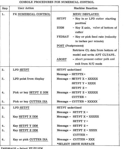
Table 1-2
CONSOLE PROCEDURES FOR NUMERICAL CONTROL
Step User Action Machine Reaction
1. FK NUMERICAL CONTROL MENU DISPLAYED
SETPT - Key in or LPD cutter starting
"-position
ZDIM - Key Z axis, value of bottom of
cutter
FEDRAT - Key or pick feed rate (velocity
in inches per minute)
POST (Postprocess)
I
Retrieve CL data from bottom of
model and write APT CLTAPE.
ABORT - Abort present cutter path and
exit from N/C mode
2. LPD SETPT SETPT underlined
Message - SETPTX=
3. LPD point from display Message - SETPT X = XXXXX
SETPT Y = XXXX
SETPT Z =
4. Pick or key SETPT Z DIM Message - SETPT Z = XXXXX
CUTTER =
5. Pick or key CUTTER DIA Message - CUTTER = XXXXX
2. LPD SETPT SETPT underlined
Message - SETPT X =
3. Key SETPT X DIM Message - SETPT X = XXXXX
SETPT Y=
4. Key SETPT Y DIM Message - SETPT Z =
5. Key SETPT Z DIM Message - SETPT Z = XXXX
CUTTER =
[image:40.613.33.532.117.710.2]Table'1-2 (Cont.)
Step User Action Machine Reaction
2. LPD Z DIM Z DIM underlined
Message
-
Z DIM=
3. Pick or key Z DIM Message
-
Z DIM=
XXXXX* SELECT DRIVE SURFACE
2. LPD FEDRAT FEDRA T underlined
Message
-
FEDRAT=
3. Pick or key FEDRA T Message
-
FEDRAT=
XX*SELECT DRIVE SURFACE
2. LPD POST
- -
(APT INTERFACE)POST underlined
Message
-
MACHIN/3. Pick or key MACHIN Message
-
MACHIN/XXXXX
STATEMENT
3A. FKACCEPT SCALE
=
4. pick or key SCALE Message
-
SCALE=
XXJCXWrites CLTAPE to input to APT system
2. LPD ABORT ABORT underlined
All N / C output deleted from the model
-exit from N / C mode
2. LPD PT
-
Cutter displayed at PT selectedCL placed in model
, *SELECT DRIVE SURFACE
2. LPD ELEM Message
-
SELECT - CKSURF3. LPD CKSURF " Cutter displayed at intersection of elements
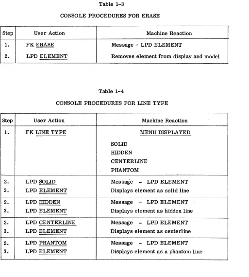
Table 1-3
CONSOLE PROCEDURES FOR ERASE
Step User Action Machine Reaction
1. FK ERASE Message - LPD ELEMENT
2. LPD ELEMENT Removes element from display and model
Table 1-4
CONSOLE PROCEDURES FOR LINE TYPE
Step User Action Machine Reaction
'
-1. FK LINE TYPE MENU DISPLAYED
SOLID
I
HIDDENCENTERLINE
PHANTOM
2. LPD SOLID Message
-
LPD ELEMENT3. LPD ELEMENT Displays element as solid line
I
2. LPD HIDDEN Message
-
LPD ELEMENT3. LPD ELEMENT Displays element as hidden line
2. LPD CENTERLINE Message
-
LPD ELEMENT3. LPD ELEMENT Displays element as centerline
2. LPD PHANTOM Message
-
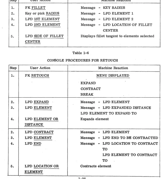
LPD ELEMENT [image:42.612.42.555.94.664.2]Table 1-5
CONSOLE PROCEDURES FOR FILLET
Step User Action Machine Reaction
1. FK FILLET Message - KEY RADIUS
2. Key or pick RADIUS Message - LPD ELEMENT 1
3. LPD 1ST ELEMENT Message - LPD ELEMENT 2
4. LPD 2ND ELEMENT Message - LPD LOCATION OF FILLET
CENTER
5. LPD SIDE OF FILLET Displays fillet tangent to elements selected
CENTER
Table 1-6 .
CONSOLE PROCEDURES FOR RETOUCH
Step User Action Machine Reaction
1. FKRETOUCH MENU DISPLAYED
. EXPAND
CONTRACT
BREAK
2. LPD EXPAND Message - LPD ELEMENT
3. LPD ELEMENT Message - LPD EXPANDED DISTANCE
LPD ELEMENT TO EXPAND TO
4. LPD ELEMENT OR Expands element
DISTANCE
2. LPD CONTRACT Message - LPD ELEMENT
3. LPD ELEMENT Message - LPD END TO BE CONTRACTED
4. LPD END Message - LPD LOCATION TO CONTRACT
-TO
LPD ELEMENT TO CONTRACT
[image:43.618.56.569.158.731.2]Step
2.
30 4.
Step
1.
2.
3.
4.
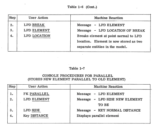
Table 1-6 (Cont.)
User Action Machine Reaction
----LPD BREAK Message
-
LPD ELEMENTLPD ELEMENT Message
-
LPD LOCATION OF BREAKLPD LOCATION Breaks element at point normal to LPD
location. Element is now stored as two
separate entities in the model.
Table 1-7
CONSOLE PROCEDURES FOR PARALLEL
(STORES NEW ELEMENT PARALLEL TO OLD ELEMENT)
User Action Machine Reaction
FK PARALLEL Message - LPD ELEMENT
LPD ELEMENT Message - LPD SIDE NEW ELEMENT
TO BE
LPD SIDE
- -
Message-
KEY NORMAL DISTANCE [image:44.612.43.552.82.504.2]T·able 1-8
CONSOLE PROCEDURES FOR CmCLE
Step User Action Machine Reaction
1. FK CmCLE Message - KEY X DIMENSION
Message
-
LPD POINT2. Key or pick X DIMENSION Message - KEY Y DIMENSION
3. Key or pick Y DIMENSION Message - KEY RADIUS
4. Key or pick RADIUS Displays circle
2. LPD POINT Message - KEY RADIUS
LPD POINT 2
3. Key or pick RADIUS Displays circle
2. LPD POINT Me,s sage - KEY RADIUS
LPD POINT 2
3. LPD POINT 2 Message
-
LPD CENTER DffiECTIONLPD POINT 3
4. LPD CENTER DffiECTION Message - KEY RADIUS
5. Key or pick RADIUS Displays circle
2. LPD POINT Message - KEY RADIUS
LPD POINT 2
3. LPD POINT 2 Message
-
LPD CENTER DffiECTIONLPD POINT 3
4. LPD POINT 3 Displays circle
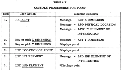
-Table 1-9
CONSOLE PROCEDURES FOR POINT
Step User Action Machine Reaction
1. FK POINT Message - KEY X DIMENSION
Message - LPD PHYSICAL LOCATION
Message
-
LPD 1ST ELEMENT OFINTERSECTION
2. Key or pick X DIMENSION Message
-
KEY Y DIMENSION3. Key or pick Y DIMENSION Displays point
2. LPD LOCATION OF POINT Displays point
2. LPD 1ST ELEMENT Message - LPD 2ND ELEMENT OF
INTERSECTION
3. LPD 2ND ELEMENT *Displays point
*If one or both elements are circles or curves an additional LPD is required to indicate which of multiple intersections the point is to be stored.
Table 1-10
CONSOLE PROCEDURES FOR LINE THROUGH POINT AT DmECTION
Step User Action Machine Reaction
1. FK LINE THRU POINT AT MENUDISPLA YED
DffiECTION HORIZONTAL
VERTICAL
PARALLEL
PERPENDICULAR
[image:46.620.53.546.97.377.2]Table 1-10 (Cont.)
Step User Action Machine Reaction
2. LPD HORIZONTAL Message - KEY X DIM:ENSION
Message - LPD POINT
Message - LPD TANGENT CIRCLE
3. Key or pick X DIMENSION Message - KEY Y DIMENSION
4. Key or pick Y DIMENSION *Displays Line
3. LPD POINT Displays Line
3. LPD TANGENT CIRCLE Message - LPD SIDE OF CmCLE THAT
LINE IS TANGENT
4. LPD TANGENT SIDE OF *Displays line
CmCLE
2. LPD VERTICAL
Procedure same as HORIZONTAL
2. LPD PARALLEL Message - KEY X DIM:ENSION
Message. - LPD POINT
Message - LPD TANGENT CmCLE
3. Key or pick X DIM:ENSION Message - KEY Y DIM:ENSION
4. Key or pick Y DIMENSION Message - LPD PARALLEL LINE
5. LPD PARALLEL LINE *Displays line
3. LPD POINT Message - LPD PARALLEL LINE
4. LPD PARALLEL LINE I *Displays line
3. LPD TANGENT CmCLE Message - LPD SIDE OF CmCLE THAT
LINE IS TANGENT
4. LPD TANGENT SIDE OF Message
-
LPD PARALLEL LINECmCLE
5. LPD PARALLEL LINE *Displays line
[image:47.612.77.568.89.647.2]Table 1-11
CONSOLE PROCEDURES FOR LINE POINT TO POINT
Step User Action Machine Reaction
1. FK LINE POINT TO POINT Message - KEY X DIMENSION
Message - LPD POINT
Message - LPD TANGENT CIRCLE
2. Key using typewriter or pick Message - Key Y DIMENSION
with light pen X DIMENSION
3. Key or pick Y DIMENSION Message - Key X DIMENSION
Message - LPD POINT
Message - LPD TANGENT
Message - CIRCLE
.. '
4. Repeat steps 2 and 3 Displays line
4. LPD PREVIOUSLY STORED Displays line
POINT
4. LPD CIRCLE Message
-
LPD SIDE OF cmCLE THATLINE IS TANGENT
5. LPD SIDE OF CIRCLE LINE Displays line
IS TANGENT TO
2. LPD POINT Message - KEY X DIMENSION
Message - LPD POINT
Message - LPD TANGENT CmCLE
3. LPD 2ND POINT Displays line
3. Key or pick X DIMENSION Message - KEY Y DIMENSION
4. Key or pick Y DIMENSION Displays line
3. LPD TANGENT CmCLE Message - LPD SIDE OF CmCLE THAT
LINE IS TANGENT
4. LPD TANGENT SIDE OF Displays line
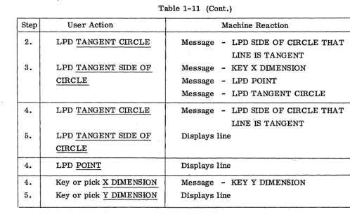
T~le 1-11 (Cont.)
Step User Action Machine Reaction
2. LPD TANGENT CIRCLE Message - LPD SIDE OF cmCLE THAT
LINE IS TANGENT
3. LPD TANGENT SIDE OF Message - KEY X DIMENSION
CIRCLE Message - LPD POINT
Message - LPD TANGENT cmCLE
4. LPD TANGENT CmCLE Message - LPD SIDE OF CmCLE THAT
LINE 'IS TANGENT
5. LPD TANGENT SIDE OF Displays line
CmCLE
4. LPD POINT Displays line
4. Key or pick X DIMENSION Message - KEY Y DIMENSION
5. Key or pick Y DIMENSION Displays line
Table 1-12
CONSOLE PROCEDURES FOR DIMENSIONING INFORMATION
Step User Action Machine Reaction
1. FK DIMENSION MENU DISPLAYED
HORIZONTAL
VERTICAL
PARALLEL
OFFSET
ANGLE
RADIUS
D:rAMETER
[image:49.621.70.568.101.410.2]Table 1-12 (Cont.)
Step User Action Machine Reaction
2. LPD HORIZONTAL HORIZONTAL underlined
Message - SELECT POINT 1
3. LPD 1ST POINT Message - SELECT POINT 2
4. LPD 2ND POINT Message
-
LPD LOCATION OF DIMENSION5. LPD LOCATION OF Displays dimensions, dimension lines and
DIMENSION arrowheads (they are stored in the model to
be used for hard copy if required)
2. LPD VERTICAL
Same as HORIZONTAL except dimension is vertical between points selected
2. LPD PARALLEL PARALLEL underlined
Message
-
SELECT POINT 13. LPD 1ST POINT Message - SELECT POINT 2
4. LPD 2ND POINT
.
Message - SELECT ELEMENT THATDIMENSION IS· PARALLEL TO
5. LPD ELEMENT THAT' Message
-
LPD LOCATION OFDIM IS PARALLEL TO DIMENSION
6. LPD LOCATION OF Displays dimension, dimension lines and
DIMENSION arrowheads
2. LPD OFFSET OFFSET underlined
Message - SELECT 1ST ELEMENT
3. LPD 1ST ELEMENT' Message - SELECT 2ND ELEMENT
4. LPD 2ND ELEMENT Message - LPD LOCATION OF DIMENSION
5. LPD LOCATION OF Displays dimension, dimension lines and
[image:50.615.55.538.108.662.2]