promoting access to White Rose research papers
White Rose Research Online
Universities of Leeds, Sheffield and York
http://eprints.whiterose.ac.uk/
This is an author produced version of a paper published in Journal of Dentistry.
White Rose Research Online URL for this paper: http://eprints.whiterose.ac.uk/4721/
Published paper
Evaluation of the marginal fit of three margin designs of resin
composite crowns using CAD/CAM
Effrosyni A. Tsitrou *, Simon E. Northeast, Richard van Noort
Department of Adult Dental Care, School of Clinical Dentistry, University of Sheffield, Claremont Crescent, Sheffield S10 2TA, UK
Published in Journal of Dentistry 2007; 35(1): 68 –73
Abstract
Objectives: To examine the marginal fit of resin composite crowns manufactured with the CEREC 3 system employing three different margin designs; bevel, chamfer and shoulder, by means of a replica technique and a luting agent.
Methods: Three master casts were fabricated from an impression of a typodont molar tooth and a full-coverage crown prepared with a marginal finish of a bevel, a chamfer and a shoulder. Each cast was replicated 10 times (n = 10). Scanning of the replicas and crown designing was performed using the CEREC ScanTM system. The crowns were milled from Paradigm MZ100TM composite resin blocks. The marginal fit of the crowns was evaluated with a replica technique (AquasilTM LV, Dentsply), and with a resin composite cement (RelyXTM Unicem, AplicapTM) and measured with a travelling microscope. Statistical analysis was performed using two-way ANOVA.
Results: For the replica technique the average marginal gaps recorded were: Bevel Group 105±34 mm, Chamfer Group 94±27 mm and Shoulder Group 91±22 mm. For the resin composite cement the average marginal gaps were: Bevel Group 102±28 mm, Chamfer Group 91±11 mm and Shoulder Group 77±8 mm. Two-way ANOVA analysis showed that there was no statistically significant difference between the three groups of finishing lines regardless of the cementation technique used.
Conclusions: The marginal gap of resin composite crowns manufactured with the CEREC 3 system is within the range of clinical acceptance, regardless of the finishing line prepared or the cementation technique used.
Keywords: Resin composite Resin composite crowns Dental materials CAD/CAM CEREC Marginal gap Replica technique
*Corresponding author
1. Introduction
The increasing demand for tooth-coloured restorations in the posterior region
has intensified the evolution of new restorative techniques and processing routes. The
introduction of computer-aided design/computer-aided manufacture (CAD/CAM)
technology in dentistry has allowed the shaping of high-performance materials that
could not otherwise be easily shaped to form a dental restoration.1 The CEREC
system is only one of the plethora of CAD/CAM systems available today. It was
introduced more than 15 years ago and constitutes the only one that can be used both
at the chairside and in the laboratory.2,3 Several researchers have criticized the
marginal fit of these restorations.3,4 However, improvements in the CEREC apparatus
and software have made the fit more acceptable through precise operating
procedures.5 Numerous studies have evaluated the clinical success of
computer-assisted fabrication methods and in particular the marginal accuracy of these
restorations, showing promising results.6–13
Recently a new resin composite block (Paradigm MZ100, 3M ESPE Dental
Products) has been introduced for the CEREC system, which according to the
manufacturers combines some of the best attributes of ceramics and polymers.14 For
ceramic restorations, a shoulder or broad chamfer preparation is recommended, but
for resin composite less invasive chamfer and bevel preparations have been used
extensively for direct cavity designs.15 It was therefore of interest to study whether the
application of more conservative finishing lines would influence the marginal fit of
CEREC restorations using that material. Thus, the purpose of this study was to
compare the marginal fit of resin composite crowns fabricated with the CEREC 3
CAD/CAM system employing three different margin designs: a shoulder, a chamfer
and a bevel, by means of a replica technique and a luting agent. The purpose of using
two methods of cementing the crowns was to determine any difference between the
two cementation techniques.
2. Materials and methods
A lower left first molar typodont tooth (Frasaco A3, 3–6, Frasaco Franz Sachs
& Co., GmbH) was selected in order to prepare three master casts. The intact
taking an impression, using an addition-curing vinyl polysiloxane material
(Dublisil-HC, DREVE-DENTAMID-GMBH, Lot No.: 4801 A+B, Germany). Both
proportioning and mixing were undertaken in accordance with the instructions given
by the manufacturer. On completion of setting the ring and typodont tooth were
removed and the impression was cleaned of any debris under running water and
air-drying with compressed air.
Three master casts were fabricated from the impression in blue die stone (Blue
Die Stone, TechCeram; Lot No.:990401/B) mixed in accordance to the
manufacturers’ instructions (mixing ratio P:W 100 g/22 ml). To permit a more
accurate flow of the die stone, a surface tension reduction agent (Tensilab; Lot.
C199E, Zehnmack, Italy), was applied to the surface of the silicon impression. The
mixed die stone was carefully vibrated into the impression and left to set under
vacuum for 30 min.
Each cast was prepared for a full-coverage crown according to the following
protocols: an occlusal reduction of 2 mm and an axial reduction of 1.2 mm were
prepared, using an air rotor hand-piece (W&H) followed by a speed increasing
micromotor (KaVo BELLA torque 629) for the final details. Each cast had a different
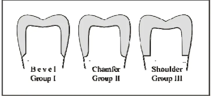
marginal design: (1) a 45° bevel, (2) a chamfer and (3) a 90° shoulder (Fig. 1). A
parallel diamond bur (Komet CE, ISO 806 314-837) was used for the preparation of
the shoulder; a round end taper diamond bur (Komet CE, ISO 806 314-881) was used
for the chamfer preparation and a bullet pointed diamond bur (Komet CE, ISO 806
314-886) for the preparation of the bevel. A tungsten carbide bur was used to refine
the margins (Ash England, FGSS 556 36/009, Komet CE ISO 500 314-H297 and
[image:4.595.88.453.570.737.2]Komet CE ISO 500 314-H283).
Figure 1 Schematic diagram of each different preparation (not to scale).
An impression was taken of each cast to fabricate a series of 10 replica dies
for each marginal design using the materials and techniques previously described.
Each replica was fixed to a special model holder provided with the CEREC Scan
(Sirona Dental Systems GmbH) and was inserted in the aligning tool before scanning.
CEREC powder (VITA Zahnfabrik, D-79713 Bad Sackingen, Germany) was applied
evenly before scanning was initiated. The Cerec 3 software (v.1.61 R991) was used
for the designing of the restorations. Correlation was selected as the design mode,
which belongs to the two-impression methods, in which the three-dimensional data of
two optical impressions are combined.16 The optical recording of the cavity is called
‘‘preparation impression’’ and the optical recording of the occlusal morphology is
called ‘‘occlusion impression’’. The latter could either be the pre-existing occlusal
surface of the tooth, or a newly waxed up occlusion. In this case, a crown was
waxed-up for the ‘‘occlusion impression’’ (Fig. 2). All scanning and designing procedures
were repeated for each replica separately. ParadigmMZ100 blocks for CEREC (size
14, shadeA3) were selected to construct 10 identical crowns for each of the three
marginal configuration groups. The scanner and the milling unit were calibrated at the
beginning of the study and recalibrated each time the computer software requested it
with the use of the calibration specimen and pins provided with the system. A new set
of milling burs was used for each group, even though not requested by the software.
[image:5.595.92.498.484.687.2]The luting space was set to 10 mm.
2.1. Measurement of marginal fit
The marginal gap was evaluated by means of a replica technique and a luting
agent. It was determined according to terminology previously reported by Holmes et
al.17 as the vertical distance from the internal surface of the crown to the prepared
[image:6.595.91.447.171.347.2]tooth surface close to the preparation finish line (Fig. 3).
Figure 3 Points of measurement of the marginal gap of different marginal situations.
2.1.1. Replica technique
A light-body silicone rubber impression material (Aquasil LVTM, green colour,
Dentsply-Detrey GmbH D-78467, Germany) was used for the purpose of the
cementation. Each crown was filled with the light-bodied material and placed on the
corresponding replica with a constant defined load of 40 N for 3 min using a
tensometer (Loyds Instrument Model LRX).
After setting of the silicone rubber the crowns were removed from the models.
The film of the impression material adhered to the inner surface of the crown in all
instances. To support the thin silicone film, a heavy-bodied material with a
contrasting colour (Aquasil Putty, blue colour, Dentsply- Detrey GmbH Lot No.:
0407000850, Germany) was placed in the crown to form one piece with the film.
After setting of the supporting heavy-bodied material each silicone replica was
removed from the crown and carefully segmented with a sharp surgical blade
buccolingually and mesiodistally into four pieces. To provide a consistent series of
locations for sectioning and measuring, an index was made with a heavy-bodied
material (Aquasil Putty). The marginal gap was measured using a travelling
2.1.2. Resin composite cement
After removal of the silicone film each crown was cleaned and was cemented
onto the replicated model with resin composite cement (RelyXTM Unicem AplicapTM;
Self-Adhesive Universal Resin Cement, Lot 179205, 3M ESPE AG, Dental Products,
D-82229, Germany). The cementation process followed the manufacturer’s
instructions and the same loading conditions were applied as for the replica technique.
After setting of the cement the models were sectioned buccolingually and
mesiodistally with a diamond wheel (LECO VC-50). The silicone index that was
made for the sectioning of the silicone replicas was used again to provide matching
locations of measurement. Four sections were produced for each model. Each section
was embedded in acrylic resin (Buehler Sampl-Kwick Fast Cure Acrylic Kit,
No.20-3560) for easier handling. In that way four acrylic embedded specimens were made
for each model, which were then polished and examined under the travelling
microscope (30 x magnifications) to measure the marginal gap of the crowns.
2.2. Statistical analysis
All data were analyzed with respect to the different preparation design. The
average marginal widths and standard deviations (S.D.) were calculated. The
statistical package SPSS was used and two-way analysis of variance (ANOVA) was
performed to look for significant differences between different fishing lines and
different cementation techniques and their interactive effect on the marginal gap.
3. Results
The mean values and standard deviations of the marginal gaps recorded for all
groups are listed in Table 1 and shown graphically in Fig. 4. Two-way ANOVA
analysis showed that the p-values for the two factors (marginal finish and cement
type) were both greater than .05 (marginal finish: p = .090, cement type: p = .364),
thus the results were not significantly different at the 5% level (Table 2). Also, as
shown in Table 2, the interactive effect of marginal finish and cement type is not
significant ( p = .781), indicating that there is no statistical difference in marginal gap
0 20 40 60 80 100 120 140 160
[image:8.595.103.454.86.261.2]BEVEL CHAMFER SHOULDER RC SR
[image:8.595.82.497.359.442.2]Figure 4 Comparison of the average values and standard deviations of the marginal gap of the Cerec crowns measured with the replica technique and with the resin cement in the three groups (mm, WS.D.). RC, resin cement; SR, silicone replica.
Table I Average values and Standard Deviations of the Marginal gap of the Cerec crowns of each marginal design. (μm, ±SD), n=10
Groups Bevel SR
Chamfer SR Shoulder SR Bevel RC
Chamfer RC Shoulder RC
Average 105 94 91 102 91 77
SD 34 27 22 28 11 8
SR silicone replica, RC resin cement
Table II Results of Two-way ANOVA analysis
Type III
Sum of Squares df Mean Squares F Sig.
Marginal Finish .003 2 .002 2.536 .090
Cement Type .001 1 .001 .841 .364
Marginal Finish and Cement
Type .000 2 .000 .248 .781
4. Discussion
The purpose of this study was to investigate the option of applying more
conservative marginal configurations compared to a traditional shoulder finish line
with the use of a CAD/CAM system and a resin composite block. The importance of
conserving tooth tissue is unquestionable and has been stated by many researchers up
till now.18–20 The principles of minimal invasive dentistry are getting more widely
[image:8.595.83.497.488.568.2]However, while there may be an impetuous to apply minimal preparation designs, it is
not clear what constrains may be imposed on tooth design by the material used and
the method of fabrication. If materials and design are inappropriate then this can
increase the probability of restoration failure.
The success of a restoration is determined by various factors, among which is
the marginal fit of the restoration. Lack of adequate fit is potentially detrimental to
both the tooth and the supporting periodontal tissues, due to cement solubility or
plaque retention.17 However, the definitions of marginal fit vary considerably among
investigators and often the same term is used to refer to different measurements, or
different terms are used to refer to the samemeasurements.17 In the present study the
marginal gap was determined according to terminology previously reported by
Holmes et al.17,23 Overcontours or undercontours of the crowns margins were not
evaluated in this study.
Two common techniques to measure the marginal gap are measurement of
embedded and sectioned specimens, and measurement of the replica of the marginal
gap. The replica technique, described initially by McLean and von Fraunhoffer, has
been a reliable and valid non-invasive method to determine the adaptation of crowns
to tooth-structure.24–26 Since then other researchers have used this method to measure
crown film thickness.23,25,26 In this study both methods have been used in order to
evaluate the effectiveness of each technique to measure the marginal gap.
The mean marginal gap of CEREC crowns reported in the current study was
between 91 and 105 mm when silicone was used as a cement and 75 and 102 mm
when a resin composite cement was used. These findings are far from the theoretically
based requirements according to which the cementation film thickness should be
between 25 and 40 mm.27 However, most authors agree that marginal openings or
inaccuracies of less than 120 mm seem to be in the range of clinical acceptance with
regard to longevity.24,25,28,29
For different all-ceramic systems the marginal gap reported in several studies
was within the range of 1–161 mm.23,28,30,31 With regard to the values of gap widths of
Cerec crowns reported by previous investigators a comparison of the results can be
confusing. Variations in type of tooth used, differences in restoration designs,
preparation procedures, testing methods and whether the fit was determined before or
after luting, are parameters that will influence the results obtained. Moreover, to the
Cerec crowns exist in the literature. In a recent study by Nakamura et al. the marginal
gaps of CAD/CAM crowns reported ranged between 95 and 108 mm when the luting
space was set to 10 mm, which are close to the results reported in the present study.32
However, the measuring method adopted differed from that of the current study as the
marginal gap was measured without cementing the crowns with the use of a profile
projector.
In another study by Bindl et al., the average marginal width reported for
anterior Cerec crowns was much lower than the average marginal gaps reported in
that study (59.9±7 mm).33 However, the methodology followed in that study differed
in many ways to the methodology followed in the present study. One difference was
the fact that the fit of the anterior crowns was checked prior to cementation with a
coloured chap-stick and all marked areas were manually removed. In that way,
though, the luting space set by the computer was increased manually. Moreover,
Nakamura et al. in their study concluded that when the software setting for the luting
space was set to 30–50 mm the quality of marginal fit was better than when the luting
space was set to 10 mm.32 The values reported by Nakamura et al. when the luting
space was set to 30 or 50 mm was within the range of 53–67 mm, which are not very
far from the marginal gap reported by Bindl et al. In the present study no coloured
chap-stick or other fit checker was used to remove manually any premature contacts,
as there was no sign that the crowns did not fully sit when examined visually. For the
same reason that the crowns had an acceptable fit when examined visually, the luting
space in the parameter settings in the Cerec 3 software was left at 10 mm. However, it
may be worth investigating further if the use of different luting spaces would have
produced better readings of the marginal gap.
The results obtained in the current study show that there were no statistically
significant differences in the marginal gap between the three groups of finishing line
(Bevel, Chamfer, and Shoulder) regardless the cementation technique used. In
addition, power law calculations showed that for the sample size used to prove any
statistically significant difference, the discrepancy between the groups would have
had to be greater than ~50 mm and this was not the case.
Although there was no significant difference between marginal gaps for
crowns made with the same finishing line, whether cemented with light bodied
silicone material or resin composite cement, the values reported for the resin
This could be attributed to the different flow ability of the materials, with the resin
composite displaying better flow. However, the results of the study show that for the
materials used both methods demonstrate similar results and are both reliable in
measuring the marginal gap.
Finally, based on the observation that the marginal widths reported for the
bevel and the Chamfer Group were within the clinical acceptable marginal gap limits,
it could be concluded that crowns with a marginal finish other than shoulder can be
fabricated with the Cerec 3 system, offering the same level of marginal adaptation as
other all-ceramic crowns. However, further in vitro and in vivo studies are necessary
if a less invasive approach is to be adopted with the use of resin composite blocks.
5. Conclusions
Within the limitations of this study, it can be concluded that the mean
marginal gaps of resin composite crowns fabricated with the use of CEREC 3 system
were within the range of clinical acceptance regardless the finishing line prepared.
Also for the materials used both methods to measure the marginal gaps were found to
be sufficient and not statistically significant different. However, in order to accept a
less invasive design with the use of that system more studies will be needed to
examine other aspects of marginal fit and also the behaviour of other restorative
materials.
Acknowledgements
We would like to thank 3M/ESPE for their donation of resin composite blocks. We
would also like to thank Mrs. J. Russell for her assistance in the statistical analysis of
References
1. Jedynakiewicz NM, Martin N. CEREC: science, research, and clinical application.
The Compendium of Continuing Education in Dentistry 2001;22:7–13.
2. Mormann WH, Brandestini M, Lutz F, Barbakow F. Chairside computer-aided
direct ceramic inlays. Quintessence International 1989;20:329–39.
3. Hickel R, Dasch W, Janda R, Tyas M, Anusavice K. New direct restorative
materials. FDI Commission Project. International Dental Journal 1998;48:3–16.
4. Bayne SC, Heymann HO. CAD/CAM in dentistry: present and future applications.
Quintessence International (Current Concepts) 1996;27:431–3.
5. Mormann WH, Bindl A, Richter B, Apholt W, Toth RT. CEREC computer aided
design/computer-integrated manufacturing. Zurich, Switzerland: Foundation of
Computer-Assisted Dentistry Publishers; 1999.
6. Huerzeler MB, Fett H, Mormann WH. Marginal adaptation of CEREC CAD/CAM
inlays after 3.5 years. In: Mormann WH, editor. International symposium on
computer restorations state of the art of the CEREC method. Quintessence, 1991.
p.417–23.
7. Mormann WH, Kreicji I. Clinical and SEM evaluation of CEREC inlays after 5
years in situ. In: Mormann WH, editor. International symposium on computer
restorations state of the art of the CEREC method1991:25–32.
8. Peters A, Bieniek K. SEM examination of the marginal adaptation of computer
machined ceramic restorations. In: Mormann WH, editor. International symposium on
computer restorations state of the art of the CEREC method. Quintessence, 1991. p.
365–71.
9. Inokoshi S, Van Meerbeek B, Willems G, Lambrechts P, Braem M, Vanherle G.
Marginal accuracy of CAD/CAM inlays made with the original and the updated
software. Journal of Dentistry 1992;20:171–7.
10. Isenberg BP, Essig ME, Leinfelder KF. Three-year clinical evaluation of
CAD/CAM restorations. Journal of Esthetic Dentistry 1992;4:173–6.
11. Gladys S, Van Meerbeek B, Inokoshi S, Willems G, Braem M, Lambrechts P, et
al. Clinical and semiquantitative marginal analysis of four tooth-coloured inlay
12. Denissen H, Dozic A, van der Zel J, van Waas M. Marginal fit and short-term
clinical performance of porcelain-veneered CICERO, CEREC, and Procera onlays.
The Journal of Prosthetic Dentistry 2000;84:506–13.
13. Reiss B, Walther W. Clinical long-term results and 10-year Kaplan-Meier analysis
of Cerec restorations. International Journal of Computerized Dentistry 2000;3:9–23.
14. Rusin RP. Properties and applications of a new composite block for CAD/CAM.
The Compendium of Continuing Education in Dentistry 2001;22:35–41.
15. Aschheim KW, Dale BG. Esthetic dentistry: a clinical approach to techniques and
materials. 2nd ed. Mosby; 2001.
16. Richter B, Mormann WH. CEREC 3 full-ceramic CAD/CAM inlays and partial
crowns, computer aided design/computer integrated manufacture. Foundation of the
Advancements of Computer-Assisted Dentistry (FACD) Publishers; 2001.
17. Holmes JR, Bayne SC, Holland GA, Sulik WD. Considerations in measurement of
marginal fit. The Journal of Prosthetic Dentistry 1989;62:405–8.
18. Markley MR. Restorations of silver amalgam. The Journal of American Dental
Association 1951;43:133–46.
19. Murdoch-Kinch CA, McLean ME. Minimally invasive dentistry. The Journal of
American Dental Association
2003;134:87–95.
20. Peters MC, McLean ME. Minimally invasive operative care. I. Minimal
intervention and concepts for minimally invasive cavity preparations. Journal of
Adhesion Adhesive Dentistry 2001;3:7–16.
21. Toreskog S. The minimally invasive and aesthetic bonded porcelain technique.
International Dental Journal 2002;52: 353–63.
22. Freedman G. Ultraconservative dentistry. Dental Clinics of North America
1998;42:683–93. ix.
23. Tinschert J, Natt G, Mautsch W, Spiekermann H, Anusavice KJ. Marginal fit of
alumina-and zirconia-based fixed partial dentures produced by a CAD/CAM system.
Operative Dentistry 2001;26:367–74.
24. McLean JW, von Fraunhoffer JA. The estimation of cement film thickness by an
in vivo technique. British Dental Journal 1971;131:107–11.
25. Fransson B, Oilo G, Gjeitanger R. The fit of metal-ceramic crowns, a clinical
26. Molin M, Karlsson S. The fit of gold inlays and three ceramic inlay systems. A
clinical and in vitro study. Acta Odontologica Scandinavica 1993;51:201–6.
27. Christensen GJ. Clinical and research advancements in cast gold restorations. The
Journal of Prosthetic Dentistry 1971;25:62–8.
28. Beschnidt SM, Strub JR. Evaluation of the marginal accuracy of different
all-ceramic crown systems after simulation in the artificial mouth. Journal of Oral
Rehabilitation 1999;26: 582–93.
29. Gardner FM. Margins of complete crowns—literature review. The Journal of
Prosthetic Dentistry 1982;48: 396–400.
30. Schaerer P, Sato T, Wohlwend A. A comparison of the marginal fit of three cast
ceramic crown systems. The Journal of Prosthetic Dentistry 1988;59:534–42.
31. Sulaiman F, Chai J, Jameson LM, Wozniak WT. A comparison of the marginal fit
of In-Ceram, IPS Empress, and Procera crowns. The International Journal of
Prosthodontics 1997;10:478–84.
32. Nakamura T, Dei N, Kojima T, Wakabayashi K. Marginal and internal fit of
Cerec 3 CAD/CAM all-ceramic crowns. The International Journal of Prosthodontics
2003;16:244–8.
33. Bindl A, Windisch S, Mormann WH. Full-ceramic CAD/CIM anterior crowns and