White Rose Research Online URL for this paper:
http://eprints.whiterose.ac.uk/467/
Article:
Tesar, V. (2004) Fluidic valve for reactor regeneration flow switching. Chemical
Engineering Research and Design, 82 (A3). pp. 398-408. ISSN 0263-8767
https://doi.org/10.1205/026387604322870516
eprints@whiterose.ac.uk https://eprints.whiterose.ac.uk/ Reuse
Unless indicated otherwise, fulltext items are protected by copyright with all rights reserved. The copyright exception in section 29 of the Copyright, Designs and Patents Act 1988 allows the making of a single copy solely for the purpose of non-commercial research or private study within the limits of fair dealing. The publisher or other rights-holder may allow further reproduction and re-use of this version - refer to the White Rose Research Online record for this item. Where records identify the publisher as the copyright holder, users can verify any specific terms of use on the publisher’s website.
Takedown
If you consider content in White Rose Research Online to be in breach of UK law, please notify us by
www.ingentaselect.com=titles=02638762.htm Trans IChemE, Part A, March 2004 Chemical Engineering Research and Design, 82(A3): 398–408
FLUIDIC VALVE FOR REACTOR REGENERATION
FLOW SWITCHING
V. TESARˇ*{
Process Fluidics Group, Department of Chemical and Process Engineering, The University of Sheffield, Sheffield, UK
A
n unusual and in many respects advantageous no-moving-part valve is described, developed for switching fluid flows in a through-flow reactor that requires a periodic regeneration by temporary replacement of the process fluid by another, regeneration fluid. The unusual feature of the valve is that it is axisymmetric, built integrally into the inlet part of the reactor body. The valve operation is based upon a monostable axisymmetric variant of the Coanda effect of jet attachment to a wall. The jet is annular and there are two attachment walls of conical shape. The outer hollow cone is dominant while the auxiliary inner convex cone is small, almost vestigial. Concentrating on the performance in a no-spillover regime, experimental data obtained in cold-air laboratory tests using a full-scale model are compared with numerical flowfield computations, using unusual non-dimensional presentation.Keywords: fluidics; power fluidics; valves; jet attachment; nozzle; diffuser.
INTRODUCTION
The purpose of this paper is two-fold. First, it provides information on interesting and little known possibilities offered by power fluidics—the technique of fluid flow control by valves having no mechanical moving components (Tesarˇ, 1998a), which makes them particularly advantageous for handling hot and=or corrosive fluids, as often encoun-tered in chemical engineering (Tippetts and Royle, 1971; Tippetts, 1972; Perera and Syred, 1983; Tesarˇ, 1995). Second, it presents a confrontation of experimental data with numerical flowfield computations in a rather complex flow configuration of an often-encountered type (nozzle and diffuser flows). The behaviour of the valve is rather intricate and to avoid discussing too many too specialized details, the attention is here focused upon the basic no-spillover flow regime. The results show to what degree the simple one-dimensional analysis can be useful in designing a device the operation of which involves a complex multi-dimensional internal flowfield.
Computational Fluid Mechanics and Design of Fluid Flow Devices
The widespread availability of numerical flowfield computation software has brought substantial progress in aerodynamic design of fluid flow devices. Of course, the software is an analysis and not synthesis tool. Its purpose is verification of design decisions, that are arrived at by
mathematically less sophisticated methods, such as one-dimensional calculations of fluid energy conversion (pressure to kinetic energy and back) along estimated streamlines—and perhaps upon momentum balances for selected control volumes. The design, of course, must consider external factors, such as manufacturing possibili-ties or available space limitations. In particular, in the design of fluidic devices with typically complex-shaped cavities, considerable experience is necessary, e.g. for estimating the effects of deviations from one-dimensional flow. Experi-ments being laborious, time-consuming, and requiring expensive facilities and resources, the numerical flow field solutions are welcome as they are able to perform the tests even before the design is finalized and metal cut. However, the time and finance required to set up the computation are also considerable. Perhaps even more importantly, handling the software and evaluating the computed results also require considerable experience. Problems like choice of proper turbulence modelling make even the best available software far from fail-safe. This makes case studies like the present one important, with comparisons of computations and experiments in practical configurations from which an experience portfolio can be build.
Power Fluidics for Flow Control
This paper presents results of experimental and numerical investigations for a device which in itself may be quite interesting to chemical engineers. It is a no-moving-part fluidic valve, of a type that has so far been insufficiently discussed in literature. Its capability to control the fluid flow without moving parts brings a number of advantages, such as high operating frequency, long life, reliability, resistance to adverse effects of temperature and fluid aggressivity, and
*Correspondence to: Professor V. Tesarˇ, Process Fluidics Group, Depart-ment of Chemical and Process Engineering, University of Sheffield, Mappin Street, Sheffield S1 3JD, UK.
E-mail: v.tesar@sheffield.ac.uk {
last but not least lower cost. In the present case, the four last named factors were decisive in selecting such a fluidic valve to perform a temporary switching of a processed high temperature gas flow away from a chemical reactor. The process taking place in the reactor was a heterogeneous catalytic reaction, with the catalyst immobilized in a thin surface layer of a porous coating covering the channel walls in a monolithic ceramic matrix (Tesarˇ, 2000b). The coating required a periodic short-term regeneration during which the processed gas flow was deflected into a by-pass channel and its flow in the reactor replaced by a smaller flow rate of another, regeneration gas which created in the reactor a reduction atmosphere. Such flow switching and replacement requirement was actually similar to many other common situations in chemical engineering, arising for example in cleaning a liquid by adsorption, requiring a periodic removal of the adsorbed substances (Tesarˇet al., 1996, 2000).
Instead of mechanical alternative blocking of the inlets into the reactor and the by-pass channel, fluidic valves utilize inertial effects in fluid accelerated in a nozzle, which then cannot change its direction easily. If directed into the reactor (Figure 1), the accelerated fluid moves past the other available valve exit (into the by-pass), unless of course it meets too great a resistance in the desired path, when unwanted spillover can occur. In fact, the jet may generate an effect reverse to the spillover: a back flow in the by-pass channel towards the main nozzle due to the jet-pumping (entrainment into the jet). As a result of the spillover or jet pumping possibilities, fluidic valves require adjustment of the conditions in the whole fluidic system, especially if the no-spillover condition is to be met. Many disappointments with fluidics have been due to neglecting this aspect—besides of course the difficulties in designing the necessarily sophisticated internal geometry. Another possible source of disappointments is associated with the need to accelerate the fluid in the nozzle, since the high velocities can lead to high hydraulic losses. To decrease them, it is imperative to place a good diffuser (which, because of the necessary small wall divergence angle, tends to be long and to occupy much valuable space) in the collector that captures the jet immediately downstream from the interaction cavity of the valve.
Apart from the acceleration in the main nozzle, the fluid jet may be also assisted in being directed into the desired flowpath by the Coanda effect of attachment to a wall (Tesarˇ,
1998a). In most known bistable fluidic valves, two symmetric attachment walls on opposite sides of the jet path are used, each leading the jet towards one of the exits (Tippetts and Royle, 1971). The switching of the flow between the walls requires a pair of opposing control nozzles and two control circuits. This complicates the otherwise simple fluidic system considerably. In the present case, where one of the operational regimes prevails—the regeneration regime representing just short-duration spells—a rather unusual monostable valve operation was chosen (Tesarˇ, 1996, 1997a, b). A monostable valve has, in principle, only a single attachment wall (or has one of its attachment walls much larger, to dominate over the small opposite one). After each start, the flow always attains the preferred operating regime, in which it remains as long as the control signal is not applied. Only one control circuit suffices, its action causing a flow separation from the dominant wall.
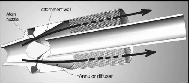
[image:3.595.305.545.71.183.2]After initial attempts with planar version, roughly corre-sponding to Figure 1, an unusual axisymmetric configura-tion was developed (first discussed in Tesarˇ, 1996). In this, as shown in Figures 2 and 3, the jet is of annular cross section, the attachment walls are of conical shape (one a convex cone, the other concave) and the switching takes place by radial movements of the jet. Despite the existence of the second attachment wall, the valve is not bistable. It does not possess two stable regimes and returns to its single stable regime as soon as the control signal flow ceases. This behavioural asymmetry is quite natural in the
Figure 1.The basic idea of flow switching temporarily into the by-pass by the jet-deflection monostable Coanda-effect fluidic valve, shown here in the initially considered planar version.
[image:3.595.139.454.592.730.2]axisymmetric case because of the unequal attachment prop-erties of the two geometrically unequal conical attachment walls—the convex and the concave one—accentuated in the present case by the inner (convex) cone being just a small, vestigial one.
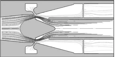
The valve is controlled by admission of another fluid into the control nozzle. This causes separation of the main jet from its attachment wall, deflecting it away from the entrance of the collector connected to the reactor and forcing it into the by-pass pipe (Figure 3). Simultaneously, a reduction atmosphere is created inside the reactor by admis-sion of a suitable regeneration gas at a smaller flow rate, about 40% of the process gas flow rate. The fact that the two required actions—jet deflection and gas replacement—are achieved simultaneously makes the present arrangement a particularly elegant solution. As seen from the example of computed flowfield in Figure 4, the regeneration gas admitted into the control nozzle pushes the main flow into the central exit pipe and then overflows past the splitter into the reactor.
THE VALVE
Design Requirements
Two basic requirements were placed upon the design by the industrial customer. Both were adverse to an aerodyna-mically effective layout. The valve was required to be simple, with only single-curvature shapes for ease of manu-facturing. Also, the valve was required to be compact as the available space for its location was severely limited. On both these counts, the otherwise quite promising planar layout initially proposed according to Figure 1 was deficient. It tends to be large and details of its shape are complex, especially as the adjacent piping is of circular cross section requiring complicating transitions into the necessarily rectangular cross sections of the valve core part.
[image:4.595.48.289.68.171.2]The axisymmetric layout, with the centrally placed by-pass pipe (shown in Figures 2 and 3) occupies much less space. There are no round-to-rectangular transitions. It makes it possible to design the valve to form the entrance
[image:4.595.48.289.237.358.2]Figure 3.In the regeneration phase, the regeneration gas admitted into the control inlet replaces in the reactor the processed gas, which is diverted into central by-pass pipe.
Figure 4.Computed fluid flow pathlines document that only the regenera-tion gas (light grey) enters the reactor in the regeneraregenera-tion phase.
[image:4.595.125.467.495.740.2]part of the reactor body. Such integrated layout saves a substantial proportion of the otherwise occupied volume.
Compromises of Detail Design
The diffuser in the collector part of the valve is required for decelerating the captured high-velocity jet before its entry into the reactor. Unfortunately, the emphasis placed on the compactness and overall short length meant there was not enough space for a longer diffuser with reasonably small apex angle. As seen in Figure 5 the apex angle of the conical diffuser is here as large as 30. This, of course, is too much and in a simple conical diffuser it would be disastrous, with flow separating from the walls. In the present case the flow does not separate from the wall, being held there by the inertia of the main annular jet. Nevertheless, the diffuser effect obtained is much less than what could be obtained in principle. Fortunately, the customer did not insist on any high overall aerodynamic performance.
Another immediately apparent aspect indicative of small emphasis placed on performance is the extremely simple shape of the splitter—the part of the valve between the central by-pass exit and the annular outer exit into the reactor. As seen in the accompanying illustrations (e.g. Figures 2 or 5), the splitter was simply formed by a plain end of the by-pass pipe. This is in direct contradiction to the quite often elaborate splitter shapes common in fluidic diverters as shown, for example, by Tippetts and Royle (1971), but certainly helps in keeping the manufacturing cost low. In fact, at a later stage the valve was re-designed for a different task (Tesarˇ, 1997a, b), in which performance figures became more important and the later designs then used sophisticated splitter shapes with semi-steroidal cavity facing the main nozzle. This, however, is a subject of differ-ent publications (Tesarˇet al., 1997; Tesarˇ and Reisenberger, 1999). The inner (convex) cone helps in establishing some diffuser effect also in the central collector, connected with the by-pass pipe, but this is again too short to be really effective.
EXPERIMENT Laboratory Model
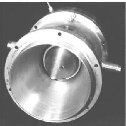
[image:5.595.317.532.256.470.2]The laboratory model, shown in Figures 5 and 6 was built at full scale for a 150 mm o.d. reactor matrix with a central 55 mm i.d. by-pass pipe. The centrebody upstream, inside the annular main nozzle—with exchangeable small inner cone at its downstream side—is held by two 3 mm diameter thin crossed rod struts which cause minimal disturbances to the flow (no strut wakes could be detected downstream from the nozzle). The locations of the supply S and output Y terminal are specified by the positions of the corresponding pressure taps, Figure 7. Ideally, the taps should be located at an infinite cross section (and hence zero fluid kinetic energy), but this is not practically possible: the cross
[image:5.595.108.487.529.741.2]Figure 6. Photograph of the upstream part of the laboratory model showing the dominant concave outer attachment wall and the small inner convex cone.
sectional area at S is AS¼0.00437 m2 and that at Y is
AY¼0.0148 m2. In the tests discussed here, the model was operated with cold air admitted to both main and control nozzles. The reactor matrix was not used and the central by-pass pipe was held in its position by perforated discs, as shown in Figure 7. The disc perforations could roughly simulate the pressure drop caused by the matrix. The downstream disc consisted of two perforated plates, one of them rotatable. Turning it moved its perforations progres-sively out of alignment with those in the fixed plate, thus varying the area available for air flow into the atmosphere. This variable loading of the valve was used in measurements of its loading characteristics. Of course, the predominantly quadratic flow characteristic of the perforations could not match the aerodynamic properties of the reactor matrix with its predominantly frictional loss character (Tesarˇ, 1998b), but this is immaterial in the tests with a particular adjusted loading pressure drop.
Scope of the Tests
The hydrodynamic conditions were adjusted for the fluidic valve to operate as closely as possible (considering temperature variations) in the no spillover regime, i.e. with 100% supplied processed gas passing through the reactor. As a consequence, a considerable proportion of the tests was devoted to measurements in the no-spillover regime, with Reynolds number as independent variable. In the present paper, the results of these tests are discussed and compared with the numerical computations. The airflow rates were measured with orifice meters. Pressure drops both across the valve as well as on the orifice meters were measured using digital electronic manometer ‘Barocell’.
For proper adjustment of the desirable regime and assess-ment of the effects of possible conditions deviating from the desirable ones, another set of experiments—not discussed here—investigated the loading characteristics of the valve.
Finally, in another set of experiments the attention concentrated on the control characteristics needed for the proper design of the control circuit. These tests were also later verified by numerical computations, an example of which is shown in Figure 4, but their discussion in full would make this paper too long and only one diagram (Figure 19) is here presented.
COMPUTATIONS
Numerical Model
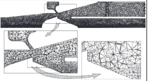
The opportunity for computational verifications arose much later—and the effort was therefore aimed at simulat-ing the experimental conditions. To make it as close as possible, it was decided to include even such details as the perforations in the discs holding the central pipe (Figure 7). The perforation holes break the axial symmetry and their inclusion meant that, instead of the two-dimensional problem in the meridian plane, a three-dimensional compu-tation model (Figure 8) was used. It was based on spatial periodicity, occupying a 15 sector between two symmetry planes passing through the valve axis. The boundary condi-tions were specified at the three terminals: at the control inlet X (constant velocity, actually zero at the regimes discussed here), in the vent exit V at the end of the by-pass pipe (in
general a pressure level, but actually substituted by more convenient zero velocity condition in the no-spillover tests of present interest), in the supply pipe (constant velocity), and in the perforations (constant pressure) of the down-stream disc holding the by-pass pipe. In the latter two instances, the boundary conditions were specified quite far from the experimental terminal locations: quite far upstream from S and also quite far downstream from Y. Flow rates and pressure values in S and Y were computed by surface integration in the computed flowfield over virtual planes set perpendicular to the valve axis.
The discretization grid used was an unstructured tetrahe-dral one, gradually refined in locations of high velocity gradients. Because of the refinements, not all runs were performed under the exactly same conditions: a typical grid used, shown in Figure 9, possessed 86,823 cells, 188,985 faces and 22,557 nodes.
Computations
[image:6.595.307.543.69.201.2]Solutions were obtained with an implicit segregated finite volumes scheme using the two-equation (k–e) turbulence model with standard values of model coefficients and standard wall function, with renormalization group modifications for treatment of the low turbulence Reynolds number situations. Another possible reason for some slight differences between the runs was the selected convergence criterion: in the later runs, after confidence in the results was
Figure 8. The computational domain approximated the laboratory test conditions, including the perforated discs as the aerodynamic loading. The outer attachment cone continues as diffuser inside the collector.
[image:6.595.307.545.598.729.2]gained, more time could be devoted to individual computa-tions by requiring all relative values of the residua to be less than 0.0001. Altogether 17 separate computation runs were performed, covering the nozzle exit Reynolds numbers range betweenRe¼819 andRe¼9014.
RESULTS
Measured and computed pressure differences between the terminals were compared converted into dimensionless form. Two options are available. The pressure drops may be related to kinetic energy term in the energy conservation equation to obtain Euler number. An unusual but interesting alternative used here is a presentation by dimensionless pressure parameter Te, called the Tesarˇ number by an unknown author (Anonymous, 2000), relating them to the dissipated energy term (Tesarˇ, 2000a):
Te¼2AbjPj _ M Mn
(1)
where A is cross-section of the nozzle exit, DP is the measured (or computed) pressure drop,b is the nozzle exit annulus width, MM_ is the mass flow rate, and n is fluid viscosity, the result being a product of Euler number and Reynolds number (Tesarˇ, 2003a). This unusual parameter was introduced in the context of very low Reynolds number microfluidics (Tesarˇ, 2001), where it is particularly useful as an asymptotic reference (Tesarˇ, 2003a), reaching a constant asymptotic value in the subdynamic regime limitRe!0.
The pressure drops themselves would provide a distorted information unless presented together with a term represent-ing the changes of fluid-specific kinetic energy. Unfortu-nately, local velocities needed for its evaluation are not exactly known at the design stage and in the experiments it can usually be computed only approximately (using a simplifying assumption of one-dimensional flow) from the flow rate. For direct comparisons with the experimental data, the same evaluation procedure was applied to the computed pressure results, even though the actual velocity distribu-tions were known.
Main Nozzle Pressure Loss
For the differences in specific energy between S and the nozzle exit, following the schematic Figure 10, the energy conservation condition for one-dimensional flow demands:
epþ pressure
ekþ
kinetic
EuSek¼0
dissipated (2)
with dissipated energy related to the kinetic energyekin the nozzle exit. The classical non-dimensionalization using Euler numberEu(Tesarˇ, 1987, 1988) proceeds by dividing all terms in equation (2) byek. Here, however, the standard expressions for the kinetic and pressure specific energy,
v(P
vPS)þ
u2
2
u2S 2 þEuS
u2
2 ¼0 (3)
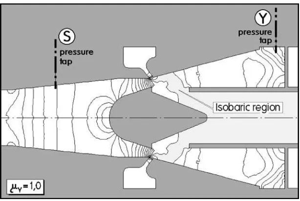
[image:7.595.365.483.68.169.2]are used for evaluatingTe. In fact the jet does not issue into the large constant-pressure space assumed in Figure 10, but the computed pressure field in Figure 11 shows the space downstream from the nozzle to be a part of a large constant pressure region extending up to the vent terminal V, so that inserting the vent pressurePVas the downstream pressure is
Figure 10. Schematic diagram of the nozzle flow used to derive the dimensionless expression for the pressure drop across the main nozzle.
[image:7.595.143.450.535.741.2]justifiable. The assumption of the one-dimensionality permits evaluation of the velocities from the flow rate:
vP Sþ
(MM_v)2 2 1 A2 1 A2 S
þEuS
2 _ M Mv A 2
¼0 (4)
so that the result may be non-dimensionalized to
TeSRe(1’S2)EuSRe¼0 (5)
using a variant of equation (1)
TeS¼2AbPS _ M Mn
(6)
and using the expression for nozzle exit Reynolds number
Re¼MM_vb
An (7)
as well as the area ratio
’S¼A=AS (8)
which in present case has numerical value’S¼0:513:
As a result, the non-dimensionalized pressure drop equa-tion for the main nozzle is
TeS¼(1’2S)ReþEuSRe (9)
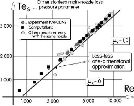
ComputedTeSvalues plotted in Figure 12 as a function of
Reexhibit a good agreement with experimental data (some of them obtained with the same nozzle used in a different device, Tesarˇ, 2003b) and agree with the expected general picture ofTe¼f(Re) dependence as presented in the sche-matic Figure 13. The conditions are, of course, far from the sub-dynamic (SD atRe!0 in Figure 13) range of constant
Te, but they are also far from the other limit Re! 1 of constant Eu. Both experimental and numerical results are seen not to differ considerably from the values for the loss-less dimensionloss-less pressure difference
TeS¼(1’2S)Re (10)
The vertical distance between the data and the line of equation (10) represents the effect of hydraulic losses in the nozzle. Despite the rather complex annular shape, the
energy dissipation (mainly in the wall boundary layers) in this favourable pressure gradient situation is quite small.
The presentation in Figure 12 provides a demanding test for the data accuracy. Plotted values are obtained as rather small differences between large values, which lead to relatively large scatter (in some cases even leading to wrong sign of the loss)—in the computed data the scatter is mainly due to the finite (non-zero) convergence limit. Nevertheless, the results indicate quite high predictive value of the computations and also acceptability of the one-dimensional approach.
Collector and its Diffuser
On the other hand, the analogous results for the collector must be handled with much more caution. The pressure rise in the diffuser is computed from the one-dimensional energy conservation condition similar to equation (2):
epþ
pressure
ekþ
kinetic
EuYek¼0
dissipated (11)
Here, however, the evaluation of the pressure and velocity in
v(P
YPv)þ
u2Y 2
u2
2 þEuY
u2
2 ¼0 (12)
corresponding to equation (3) is more questionable. It is impossible to give any simple (and simply evaluated) value for the collector entrance velocity. The schematic diagram Figure 13, based upon the simple model of Figure 14, uses the knowingly oversimplificated assumption of taking the nozzle exit velocity instead, so that equation (12) becomes
vP Yþ
(MM_v)2 2 1 A2 Y 1 A2
þEuY
2 _ M Mv A 2
¼0 (13)
[image:8.595.335.498.64.216.2] [image:8.595.47.286.94.197.2]neglecting the complicated velocity profile at the collector entrance and the loss of jet momentum before it reaches the entrance. In fact, the latter computations as presented in Figure 15 show a recirculatory motion in the collector, which strains the assumptions of the one-dimensionality at the downstream conditions in Y to the very extreme. Again,
Figure 12. Dimensionless pressure drop across the main nozzle as a function of the Reynolds number: comparison of experimental and computed values.
[image:8.595.52.283.538.721.2]equation (13) is non-dimensionalized, using now the slightly altered definitions:
TeY¼2AbPY _ M Mn
(14)
and the downstream-to-upstream area ratio,
’Y¼AY=A (15)
here with numerical valuejY¼6.6.
The resultant equation used to process experimental and numerical data is
TeY¼(1’Y2)ReEuYRe (16)
Although closely related to equation (9), some of the conven-tions (e.g. using the vent terminal V as the reference in evaluating the pressure differences, cf. Figure 19) cause the derived expression for the diffuser to differ. Ideally, the flow through the diffuser would produce a pressure increase corresponding to the loss-less expression
TeY¼(1’Y2)Re (17)
in the present case of largejYvery near toTeY¼Re. Here the hydraulic losses (including the effects of deviations from the one-dimensionality assumption) decrease theTeYvalues, Figure 17. As seen in Figure 16, again presenting the
[image:9.595.316.534.66.246.2]dependence of the dimensionless pressure parameter on the Reynolds number similar to the nozzle case in Figure 12, the decrease is considerable. On the other hand, the mutual correspondence of experimental and numerically computed TeY values in Figure 16 remains reasonable, despite the general doubts over applicability of the simple isotropic turbulence model in jet flows of similar com-plexity. A closer inspection shows that while the experi-mental data in Figure 16 tend to divert progressively from the loss-less straight line with decreasingRe, the numerical results here tend to exhibit an improbable opposite tendency. A reasonable explanation may be in the treatment of low Reynolds number turbulence. As shown in Figure 18, turbulence effects tend to be decisive in this flowfield with flows of opposing direction meeting in the centre of the recirculation loop. It is, after all, quite unlikely that such an elongated loop would remain stable—it is likely to decom-pose into a series of vortices with aspect ratio closer to 1,
[image:9.595.105.233.68.168.2]Figure 14.Schematic one-dimensional representation of the flow through the collector part of the valve.
[image:9.595.147.446.527.741.2]most probably shed and generated anew. To compute them properly, a more advanced turbulence model—probably a time-dependent variant to deal with the vortex shedding— would be necessary.
The diffuser in the described valve was designed mainly with manufacturing simplicity and compactness require-ments in mind. As a result, being too short and having a too wide entrance, the diffuser performance is rather poor. The computed pathlines in Figure 16 show that, while there is no separation from the outer conical wall, which would be the cause for inferior performance in simple conical diffu-sers, the flow entering the collector here does not fill the whole entrance cross section. Driven by the jet-pumping action, a reverse flow takes place at the inner side.
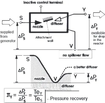
Pressure Recovery
A parameter characterizing best the behaviour of fluidic valves in the no-spillover regime is the magnitude of the pressure recovery
Y¼TeY TeS
(18)
This is simply evaluated from the present data as the ratio of
TeYplotted in Figure 16 to the valueTeSplotted in Figure 12.
[image:10.595.93.243.62.218.2]Although far from the indicated ideal value, the pressure recovery around 50% is quite acceptable—in fact surpris-ingly good considering the poorly operating diffuser. A number of fluidic valves are known to operate with pressure
Figure 17.Schematic dependence of the pressure difference parameterTe on Reynolds numberRefor a collector: hydraulic loss subtracted from the ideal loss-less pressure increase.
[image:10.595.333.515.66.244.2]Figure 18.Computed distribution of the kinetic energy of turbulent fluctuations, indicating the extreme values in the shear region between the two opposing flows in the diffuser.
Figure 19.Schematic representations of the valve and the pressure varia-tions along a typical streamline (drop in the nozzle, increase in the collector) defining the pressure recovery.
[image:10.595.310.538.299.461.2] [image:10.595.132.462.570.731.2]recovery in the vicinity of 30% and yet are considered successful.
Evaluating more complex quantities like pressure recov-ery discernibly widens differences between the computa-tions and the experiments, although it should be said that for most practical engineering purposes the numerical predic-tions like those shown in Figure 20 must be considered admirable. There is, nevertheless, again the apparent differ-ence in the character of variations with Reynolds number: the numerically predicted increase of the pressure recovery with decreasingReis highly unlikely.
CONCLUSIONS
The described fluidic valve, developed for diverting the flow of the processed fluid and at the same time replacing it in the reactor by the regeneration fluid, is very compact, space-saving, and geometrically simple. The laboratory model shown in the illustrations may be converted in a straightforward manner into a low-cost, easily manufactured sheet metal version. For all practical purposes, the valve has unlimited life even in extreme temperature and vibration environments. It requires absolutely no maintenance.
In the present design, no particular emphasis was placed on efficiency—no large benefit was seen in decreasing the relatively low pressure drop across the valve, of the order of 0.5 kPa. There is, nevertheless, a large opportunity left for improvements—in particular a better design of the diffuser, eliminating the recirculation shown in Figure 15.
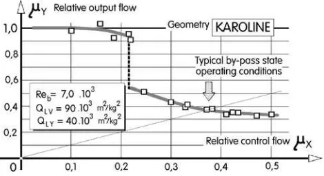
Also the control nozzle can be made more effective. The relative control flowmX0.22 required for the switching as shown in Figure 21 can be easily decreased. In the present case, however, there was no requirement of reducing the output flow (through the reactor) to zero by the switching, as would be usually the case in classical diverter valve applica-tions. The task here was to replace the process fluid in the reactor by a slightly less than 40% flow rate of a different, regeneration fluid. This is (as seen also in Figure 4) exactly what the control action does.
The presentation of the results based on the idea of the pressure parameterTe, equation (1), may be also of interest and perhaps deserves application elsewhere.
At the level of predicted pressure differences, modern commercial software (Fluent 5) used for numerical flowfield computations with a very dense discretisation mesh
performs almost perfectly. It is possible to find minor discrepancies—in the present case quite probably attributa-ble to the low Reynolds number modifications of the turbulence model or perhaps an inadequacy of the turbu-lence model in the high-shear region between flows of opposing directions—but the increased computational effort associated with the use of for example the time-dependent vortex shedding solutions does not seem to be justified for engineering design purposes.
For full investigations of the valve properties, the present analysis of the no-spillover state is just a beginning. Addi-tional investigations should include solutions at off-design, imperfect matching with the load. Instead of the single no-spillover state, such investigations would involve a large number of states, plotted as loading a curve (in fact, a number of loading curves, each for a differentRe). The other set of computations would tackle the control (¼transfer) characteristics—for different Revalues and different loads. Obviously, the number of necessary computation runs could easily become hardly manageable. Fluidics is not simple.
REFERENCES
Anonymous, 2000, High throughput catalyst testing project,iAc Newsletter, October: 8. Available at: www.iac.org.uk=download=newsletter5.pdf Perera, P.C. and Syred, N., 1983, A Coanda switch for high temperature
gas control, Paper 83-WA=DSC-26, American Society of Mechanical Engineers, ASME Winter Annual Meeting, Boston.
Tesarˇ, V., 1987, Frictional losses in nozzles, in Proceedings of PNEU-HYDRO ’87, 6th Colloquium on Pneumatics and Hydraulics, Gyor, Hungary, October.
Tesarˇ, V., 1988, Hydraulic losses in nozzles, inProceedings of FLUCOME Sheffield ’88, 2nd International Symposium on Fluid Control, Measure-ment, Mechanics and Flow Visualisation, Sheffield, September. Tesarˇ, V., 1995, No-moving-part valves for hot gas flow control, in
Proceedings of International Scientific Conference ‘Hydromechanika a tekutinove´ mechanismy’, September, Section 17, (VSˇB–Technical Univer-sity Ostrava, Czech Republic), pp 123–128.
Tesarˇ, V., 1996, Fluidicke´ ventily s mezikruhovy´m proudem prˇekla´peˇny´m mezi kuzˇelovy´mi steˇnami (Fluidic Valves with an Annular Jet Switched between Conical Walls; in Czech), in SEMINAR ’96 (KHSZ, VUT Technical University Brno), pp 11–16.
Tesarˇ, V., 1997a, Axisymmetric monostable fluidic valves, inProceedings of Workshop 97(Cˇ VUT, Prague), p 453.
Tesarˇ, V., 1997b, Axisymmetric fluidic valves for use in automobile exhaust gas aftertreatment, inProceedings of FLUCOME’97, Vol 2, Hayama, September, pp 529–534.
Tesarˇ, V., 1998a, Valvole fluidiche senza parti mobili (Fluidic valves without moving components; in Italian),Oleodinamica-pneumatica, 39(3): 216– 223.
Tesarˇ, V., 1998b, Law for pressure loss in monolithic reactor matrices, in Proceedings of Cooloquium Fluid Dynamics ’98(Institute of Thermo-mechanics, Prague), p 59.
Tesarˇ, V., 1999, Control of recycling chemical reactors by fluidic valves, in Proceedings of IX International Conference ICMR ’2000(ATR-SAWO, Bydgoszcz), pp 95–102.
Tesarˇ, V., 2000a, Asymptotic correlation for pressure-assisted jet-type microfluidic devices, in Proceedings of ‘Topical Problems of Fluid Mechanics 2000’(Institute of Thermomechanics, Prague), p 85. Tesarˇ, V., 2000b, Monolithic reactors with integral fluidic valve by-pass flow
control, inProceedings of Xth International Conference ICMR ’2000, Bydgoszcz, May, pp 23–32.
Tesarˇ, V., 2001, Microfluidic valves for flow control at low Reynolds numbers,J Visual, 4(1): 51–60.
[image:11.595.52.287.587.715.2]Tesarˇ, V., 2003a, Subdynamic behaviour of pressure-driven microfluidic valves, paper no. 192, in Proceedings of 7th Triennial International Symposium on Fluid Control, Measurement and Visualization Flucome ’03, Sorrento, August.
Figure 21.Experimental flow transfer characteristics: the switching of the main flow into the by-pass pipe takes place at control flow rate equal to
22% of the processed gas flow (experiments with air). Standard
Tesarˇ, V., 2003b, Monostable impinging-jet nozzles with fluidic control, paper no. 288, inProceedings of 7th Triennial International Symposium on Fluid Control, Measurement and Visualization Flucome ’03, Sorrento, August.
Tesarˇ, V. and Reisenberger, E., 1999, Aerodynamic investigations of trapped vortex rings, in Proceedings of 8th Annual University-wide Seminar Workshop 99, CTU Reports, Special Issue, Vol 3, Prague, p 244. Tesarˇ, V., Baumruk, P., Macek, J., Ko¨nig, A., Decker, G. and Donnerstag, A.,
1996, Fluidic valves for variable-configuration exhaust gas aftertreatment system, inXXVI Congress FISITA—Fe´deration Internationale des Soci-e´te´s d’Inge´nieurs des Techniques de l’Automobile, section A, Part 2, Prague, June.
Tesarˇ, V., Macek, J., Baumruk, P., Ko¨nig, A., Decker, G. and Pott, E., 1997, Fluidisches Verteilerventil, Schutzrechtsanmeldung 197 29 536 vom 10.07.1997, Int. Cl.6 F 16 K 11=00, German Patent Office (Patent- und Markenamt).
Tesarˇ, V., Ko¨nig, A., Macek, J. and Baumruk, P., 2000, New ways of fluid flow control in automobiles: experience with exhaust gas aftertreatment control, inProceedings of World Automobile Congress, June, paper no. F2000H192 (Society of Automotive Engineers, Seoul), p 167. Tippetts, J.R., 1972, Fluidics flow control for regenerative heat exchangers,
inProcess Engineering(Morgan, Grampian), pp 62–63.
Tippetts, J.R. and Royle, J.K., 1971, Design of flow control circuits involving bistable fluid amplifiers,Fluidics Q, 3(4): 1–15.
ACKNOWLEDGEMENTS
The experiments were supported by Volkswagen A.G., Wolfsburg, Germany.