It’s easy enough to install Wireshark and begin capturing packets off the wire—or from the air. But how do you interpret those packets once you’ve captured them? And how can those packets help you to better understand what’s going on under the hood of your network? Practical Packet Analysis shows how to use Wireshark to capture and then analyze packets as you take an in-depth look at real-world packet analysis and network troubleshooting. The way the pros do it.
Wireshark (derived from the Ethereal project), has become the world’s most popular network sniffing appli-cation. But while Wireshark comes with documentation, there’s not a whole lot of information to show you how to use it in real-world scenarios. Practical Packet Analysis shows you how to:
• Use packet analysis to tackle common network problems, such as loss of connectivity, slow networks, malware infections, and more
• Build customized capture and display filters • Tap into live network communication
www.nostarch.com
“I LAY FLAT.”
This book uses RepKover —a durable binding that won’t snap shut.
Printed on recycled paper
TH E FI N EST I N G E E K E NTE RTAI N M E NT™
SH ELV E I N: NE TW OR KIN G/ SE CU RIT Y
$39.95 ($49.95 CDN)
®
D O N ’ T J U S T S T A R E
A T C A P T U R E D
P A C K E T S .
A N A LY Z E T H E M .
D O N ’ T J U S T S T A R E
A T C A P T U R E D
P A C K E T S .
A N A LY Z E T H E M .
• Graph traffic patterns to visualize the data flowing across your network
• Use advanced Wireshark features to understand confusing packets
• Build statistics and reports to help you better explain technical network information to non-technical users Because net-centric computing requires a deep under-standing of network communication at the packet level, Practical Packet Analysis is a must have for any network technician, administrator, or engineer troubleshooting network problems of any kind.
A B O U T T H E A U T H O R
Chris Sanders is the network administrator for the Graves County Schools in Kentucky, where he manages more than 1,800 workstations, 20 servers, and a user base of nearly 5,000. His website, ChrisSanders.org, offers tutorials, guides, and technical commentary, including the very popular Packet School 101. He is also a staff writer for
WindowsNetworking.com and WindowsDevCenter.com. He uses Wireshark for packet analysis almost daily.
T E C H N I C A L R E V I E W B Y G E R A L D C O M B S, C R E A T O R O F W I R E S H A R K
T E C H N I C A L R E V I E W B Y G E R A L D C O M B S, C R E A T O R O F W I R E S H A R K
Download the capture files used in this book from
www.nostarch.com/packet.htm
PR AC TICAL
PACKE T AN ALYSIS
PACKE T AN ALYSIS
PR AC TICAL
U S I N G
W I R E S H A R K
T O S O L V E R E A L - W O R L D
N E T W O R K P R O B L E M S
C H R I S S A N D E R S
PRACTICAL PACKET
ANALYSIS
U s in g W i r e s h a r k t o S o l v e
R e a l - W o r l d N e t w o r k
P r o b l e m s
by Chris Sanders
San Francisco
PRACTICAL PACKET ANALYSIS. Copyright © 2007 by Chris Sanders.
All rights reserved. No part of this work may be reproduced or transmitted in any form or by any means, electronic or mechanical, including photocopying, recording, or by any information storage or retrieval system, without the prior written permission of the copyright owner and the publisher.
11 10 09 08 07 1 2 3 4 5 6 7 8 9
ISBN-10: 1-59327-149-2 ISBN-13: 978-1-59327-149-7
Publisher: William Pollock
Production Editor: Christina Samuell Cover and Interior Design: Octopod Studios Developmental Editor: William Pollock Technical Reviewer: Gerald Combs Copyeditor: Megan Dunchak Compositor: Riley Hoffman Proofreader: Elizabeth Campbell Indexer: Nancy Guenther
For information on book distributors or translations, please contact No Starch Press, Inc. directly:
No Starch Press, Inc.
555 De Haro Street, Suite 250, San Francisco, CA 94107
phone: 415.863.9900; fax: 415.863.9950; [email protected]; www.nostarch.com
Librar y of Congress Cataloging-in-Publication Data
Sanders, Chris,
Practical packet analysis : using Wireshark to solve real-world network problems / Chris Sanders. p. cm.
ISBN-13: 978-1-59327-149-7 ISBN-10: 1-59327-149-2
1. Computer network protocols. 2. Packet switching (Data transmission) I. Title. TK5105.55.S265 2007
004.6'6--dc22
2007013453
No Starch Press and the No Starch Press logo are registered trademarks of No Starch Press, Inc. Other product and company names mentioned herein may be the trademarks of their respective owners. Rather than use a trademark symbol with every occurrence of a trademarked name, we are using the names only in an editorial fashion and to the benefit of the trademark owner, with no intention of infringement of the trademark.
The information in this book is distributed on an “As Is” basis, without warranty. While every precaution has been taken in the preparation of this work, neither the author nor No Starch Press, Inc. shall have any liability to any person or entity with respect to any loss or damage caused or alleged to be caused directly or indirectly by the information contained in it.
B R I E F C O N T E N T S
Acknowledgments ...xv
Introduction ...xvii
Chapter 1: Packet Analysis and Network Basics ...1
Chapter 2: Tapping into the Wire ...15
Chapter 3: Introduction to Wireshark...27
Chapter 4: Working with Captured Packets...39
Chapter 5: Advanced Wireshark Features...51
Chapter 6: Common Protocols ...61
Chapter 7: Basic Case Scenarios ...77
Chapter 8: Fighting a Slow Network ...99
Chapter 9: Security-based Analysis ...121
Chapter 10: Sniffing into Thin Air...135
Chapter 11: Further Reading ...151
Afterword...154
C O N T E N T S I N D E T A I L
A CK N O W LED G M EN T S xv
I NT RO D UC TI O N xvii
Why This Book? ...xviii
Concepts and Approach ...xviii
How to Use This Book ... xx
About the Example Capture Files ... xx
1 P AC K ET AN A L YS I S A N D N ETW O RK B AS I C S 1 What Is Packet Analysis? ... 2
Evaluating a Packet Sniffer ... 2
Supported Protocols ... 2
User Friendliness ... 2
Cost ... 3
Program Support ... 3
Operating System Support ... 3
How Packet Sniffers Work ... 3
Collection ... 3
Conversion ... 3
Analysis ... 3
How Computers Communicate ... 4
Networking Protocols ... 4
The Seven-Layer OSI Model ... 4
Protocol Interaction ... 6
Data Encapsulation ... 7
The Protocol Data Unit ... 8
Network Hardware ... 8
Traffic Classifications ... 12
2 TA P PI N G IN TO TH E W I RE 15 Living Promiscuously ... 16
Sniffing Around Hubs ... 16
Sniffing in a Switched Environment ... 18
Port Mirroring ... 18
Hubbing Out ... 19
ARP Cache Poisoning ... 20
Using Cain & Abel ... 21
Sniffing in a Routed Environment ... 24
x Con t en ts in Det ai l
3
I NT RO D UC TI O N T O W I RES H AR K 27
A Brief History of Wireshark ... 27
The Benefits of Wireshark ... 28
Supported Protocols ... 28
User Friendliness ... 28
Cost ... 28
Program Support ... 28
Operating System Support ... 29
Installing Wireshark ... 29
System Requirements ... 29
Installing on Windows Systems ... 29
Installing on Linux Systems ... 31
Wireshark Fundamentals ... 31
Your First Packet Capture ... 31
The Main Window ... 33
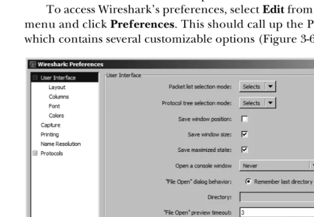
The Preferences Dialog ... 34
Packet Color Coding ... 35
4 W O RK I NG W IT H CA P TU RED P A CK ETS 39 Finding and Marking Packets ... 39
Finding Packets ... 40
Marking Packets ... 40
Saving and Exporting Capture Files ... 41
Saving Capture Files ... 41
Exporting Capture Data ... 42
Merging Capture Files ... 42
Printing Packets ... 43
Time Display Formats and References ... 43
Time Display Formats ... 43
Packet Time Referencing ... 44
Capture and Display Filters ... 45
Capture Filters ... 45
Display Filters ... 46
The Filter Expression Dialog (the Easy Way) ... 47
The Filter Expression Syntax Structure (the Hard Way) ... 47
Saving Filters ... 49
5 A DV A NC ED W IR ES HA R K F EAT UR ES 51 Name Resolution ... 51
Types of Name Resolution Tools in Wireshark ... 52
Enabling Name Resolution ... 52
Potential Drawbacks to Name Resolution ... 52
Protocol Dissection ... 53
Following TCP Streams ... 55
Con t en ts in Det ail xi
Viewing Endpoints ... 57
Conversations ... 58
The IO Graphs Window ... 59
6 C O M M O N P RO TO C O L S 61 Address Resolution Protocol ... 62
Dynamic Host Configuration Protocol ... 62
TCP/IP and HTTP ... 64
TCP/IP ... 64
Establishing the Session ... 64
Beginning the Flow of Data ... 66
HTTP Request and Transmission ... 66
Terminating the Session ... 67
Domain Name System ... 68
File Transfer Protocol ... 69
CWD Command ... 70
SIZE Command ... 70
RETR Command ... 71
Telnet Protocol ... 71
MSN Messenger Service ... 72
Internet Control Message Protocol ... 75
Final Thoughts ... 75
7 BA S IC C A S E S C EN AR IO S 77 A Lost TCP Connection ... 77
Unreachable Destinations and ICMP Codes ... 79
Unreachable Destination ... 79
Unreachable Port ... 80
Fragmented Packets ... 81
Determining Whether a Packet Is Fragmented ... 81
Keeping Things in Order ... 82
No Connectivity ... 83
What We Know ... 84
Tapping into the Wire ... 84
Analysis ... 84
Summary ... 86
The Ghost in Internet Explorer ... 86
What We Know ... 86
Tapping into the Wire ... 86
Analysis ... 87
Summary ... 88
Inbound FTP ... 88
What We Know ... 88
Tapping into the Wire ... 88
Analysis ... 88
xii Con te nt s i n De ta il
It’s Not My Fault! ... 90
What We Know ... 90
Tapping into the Wire ... 90
Analysis ... 90
Summary ... 92
An Evil Program ... 92
What We Know ... 92
Tapping into the Wire ... 92
Analysis ... 93
Summary ... 97
Final Thoughts ... 98
8 F IG H TI N G A S LO W NE TW O RK 99 Anatomy of a Slow Download ... 100
A Slow Route ... 104
What We Know ... 104
Tapping into the Wire ... 104
Analysis ... 105
Summary ... 106
Double Vision ... 107
What We Know ... 107
Tapping into the Wire ... 107
Analysis ... 107
Summary ... 109
Did That Server Flash Me? ... 109
What We Know ... 109
Tapping into the Wire ... 109
Analysis ... 110
Summary ... 111
A Torrential Downfall ... 111
What We Know ... 111
Tapping into the Wire ... 111
Analysis ... 112
Summary ... 113
POP Goes the Email Server ... 114
What We Know ... 114
Tapping into the Wire ... 114
Analysis ... 114
Summary ... 115
Here’s Something Gnu ... 115
What We Know ... 116
Tapping into the Wire ... 116
Analysis ... 116
Summary ... 119
Co nt en t s in Det ai l xiii
9
S ECU RI TY - BA S ED AN A L Y SI S 121
OS Fingerprinting ... 121
A Simple Port Scan ... 122
The Flooded Printer ... 123
What We Know ... 123
Tapping into the Wire ... 123
Analysis ... 123
Summary ... 124
An FTP Break-In ... 124
What We Know ... 125
Tapping into the Wire ... 125
Analysis ... 125
Summary ... 127
Blaster Worm ... 127
What We Know ... 127
Tapping into the Wire ... 127
Analysis ... 127
Summary ... 128
Covert Information ... 129
What We Know ... 129
Tapping into the Wire ... 129
Analysis ... 129
Summary ... 130
A Hacker’s Point of View ... 130
What We Know ... 130
Tapping into the Wire ... 131
Analysis ... 131
Summary ... 133
1 0 S N IF F IN G I NT O T HI N A I R 135 Sniffing One Channel at a Time ... 135
Wireless Signal Interference ... 136
Wireless Card Modes ... 136
Sniffing Wirelessly in Windows ... 138
Configuring AirPcap ... 138
Capturing Traffic with AirPcap ... 140
Sniffing Wirelessly in Linux ... 141
802.11 Packet Extras ... 142
802.11 Flags ... 143
The Beacon Frame ... 143
Wireless-Specific Columns ... 144
Wireless-Specific Filters ... 145
Filtering Traffic for a Specific BSS Id ... 146
Filtering Specific Wireless Packet Types ... 146
xiv Con te nt s i n De ta il
A Bad Connection Attempt ... 148
What We Know ... 148
Tapping into the Wire Air ... 148
Analysis ... 148
Summary ... 150
Final Thoughts ... 150
1 1
F UR TH ER REA DI N G 151
A FT ERW O RD 154
A C K N O W L E D G M E N T S
First and foremost, I would like to thank God for
giving me the strength and fortitude it took to
com-plete this project. When my to-do list grew longer and
longer and there was no end in sight, he was the one
who helped me through all of the stressful times.
I want to thank Bill, Tyler, Christina, and the rest of the team at No Starch Press for giving me the opportunity to write this book and allowing me the creative freedom to do it my way. I would also like to thank Gerald Combs for having the drive and motivation to maintain the Wireshark program, as well as perform the technical edit of this book. Special thanks go out to Laura Chappell, as well, for providing some of the best packet analysis training materials you will find, including several of the packet captures used here.
xvi A ckn owl ed gm en t s
accomplishment in itself. I would like to extend a very special thank you to Mandy, Barry, Beth, Chad, Jeff, Sarah, and Brandon. I couldn’t have done it without you guys behind me.
I N T R O D U C T I O N
I got my first computer when I was nine years old.
As things go with technology, it broke within about a
year. It was enough of a stretch for my family to afford
a computer in the first place, and paying for it to be
fixed was just financially impossible. However, after
a little reading and experimentation, I fixed the
com-puter myself, and that’s where my interest in technology
began.
xviii In t ro duc ti on
The great thing about packet analysis is that it has become an increasingly popular method of solving problems and learning more about networks. Thanks to the advent of user groups, wikis, and blogs, the techniques covered in this book are becoming prerequisite knowledge for some jobs. Packet analysis is a requirement for managing today’s networks, and this book will give you the jump start you need in learning how it all works.
Why This Book?
You may find yourself wondering why you should buy this book as opposed to any other book about packet analysis. The answer lies right in the title:
Practical Packet Analysis. Let’s face it—nothing beats real-world experience,
and the closest you can come to that experience in a book is through practical examples of packet analysis with real-world case scenarios. The first half of this book gives you the prerequisite knowledge you will need to understand packet analysis and Wireshark. The second half of the book is devoted entirely to practical case scenarios that you could easily encounter in day-to-day network management.
Whether you are a network technician, a network administrator, a chief information officer, a desktop technician, or simply a help desk worker, you have a lot to gain from understanding and using packet analysis techniques.
Concepts and Approach
I am generally a really laid-back guy, so I when I teach a concept, I try to do so in a really laid-back way. This holds true for the language used in this book. It is very easy to get lost in technical jargon when dealing with a technical concept, but I have tried my best to keep things as casual as possible. I’ll make all definitions clear, straightforward, and to the point, without any added fluff.
If you really want to learn packet analysis, you should make it a point to master the concepts in the first several chapters—they are integral to understanding the rest of the book. The second half of the book is purely conceptual. You may not see these exact scenarios in your work, but you should be able to apply the concepts you learn from them in the situations you do encounter.
Here is a quick breakdown of the chapters of this book.
Chapter 1: Packet Analysis and Network Basics
What is packet analysis? How does it work? How do you do it? This chap-ter covers the very basics of network communication and packet analysis.
Chapter 2: Tapping into the Wire
I n tr odu ct ion xix Chapter 3: Introduction to Wireshark
Here we’ll look at the basics of Wireshark—where to get it, how to use it, what it does, why it’s great, and all of that good stuff.
Chapter 4: Working with Captured Packets
Once you get Wireshark up and running, you will want to know the basics of interacting with captured packets. This is where you’ll learn.
Chapter 5: Advanced Wireshark Features
Once you have learned to crawl, it’s time to take off running with the advanced Wireshark features. This chapter delves into these features and goes under the hood to show you things that aren’t always so apparent.
Chapter 6: Common Protocols
This chapter shows what some of the most common network communi-cation protocols look like at the packet level. In order to understand how these protocols can malfunction, you first have to understand how they work.
Chapter 7: Basic Case Scenarios
This chapter contains the first set of real-world case scenarios. Each scenario is presented in an easy-to-follow format, where for each scenario the problem, my analysis, and a solution are given. These basic scenarios deal with only a few computers and involve a limited amount of analysis— just enough to get your feet wet.
Chapter 8: Fighting a Slow Network
The most common problems network technicians hear about generally involve slow network performance. This chapter is devoted to solving these types of problems.
Chapter 9: Security-based Analysis
Network security is the biggest hot-button topic in network administration. Because of this, Chapter 9 shows you the ins and outs of solving security-related issues with packet analysis techniques.
Chapter 10: Sniffing into Thin Air
The last chapter of the practical section of the book is a primer on wire-less packet analysis. This chapter discusses the differences between wirewire-less analysis and wired analysis and includes a quick case scenario that rein-forces what you’ve learned.
Chapter 11: Further Reading
xx In t rod uc ti on
How to Use This Book
I have intended this book to be used in two ways. The first is, of course, as an educational text that you will read through, chapter by chapter, in order to gain an understanding of packet analysis. This means paying particular attention to the real-world scenarios in the last several chapters. The other use of this book is as a reference resource. There are some features of Wireshark that you will not use very often, so you may forget how they work. Because of this, Practical Packet Analysis is a great book to have on your bookshelf should you need a quick refresher about how to use a specific feature.
About the Example Capture Files
All of the capture files used in this book are available at http://www.nostarch .com/packet.htm. In order to maximize the potential of this book, I would highly recommend you download these files and use them as you follow along with the book.
Several of these capture files were contributed by Laura Chappell of the Packet Analysis Institute and Wireshark University. Those captures are as follows:
blaster.pcap gnutella.pcap
destunreachable.pcap hauntedbrowser.pcap
dosattack.pcap http-client-refuse.pcap
double-vision.pcap http-fault-post.pcap
email-troubles.pcap icmp-tracert-slow.pcap
evilprogram.pcap osfingerprinting.pcap
ftp-crack.pcap slowdownload.pcap
1
P A C K E T A N A L Y S I S A N D
N E T W O R K B A S I C S
A million different things can go wrong
with a computer network on any given
day—from a simple spyware infection to a
complex router configuration error—and it
is impossible to solve every problem immediately. The
best we can hope to do is be fully prepared with the
knowledge and the tools it takes to respond to these types of issues. All net-work problems stem from the packet level, where even the prettiest-looking applications can reveal their horrible implementations and seemingly trust-worthy protocols can prove malicious. To better understand and solve network problems, we go to the packet level where nothing is hidden from us, where nothing is obscured by misleading menu structures, eye-catching graphics, or untrustworthy employees. Here there are no secrets, and the more we can do at the packet level, the more we can control our network and solve problems. This is the world of packet analysis.
2 Ch a pt er 1
scenarios. You’ll learn how to use the features of the Wireshark packet analysis tool to tackle slow network communication, identify application bottlenecks, and even track hackers through some real-world scenarios. By the time you have finished reading this book, you should be able to imple-ment advanced packet analysis techniques that will help you solve even the most difficult problems in your own network.
What Is Packet Analysis?
Packet analysis, often referred to as packet sniffing or protocol analysis, describes
the process of capturing and interpreting live data as it flows across a net-work in order to better understand what is happening on that netnet-work. Packet analysis is typically performed by a packet sniffer, a tool used to capture raw network data going across the wire. Packet analysis can help us under-stand network characteristics, learn who is on a network, determine who or what is utilizing available bandwidth, identify peak network usage times, identify possible attacks or malicious activity, and find unsecured and bloated applications.
There are various types of packet sniffing programs, including both free and commercial ones. Each program is designed with different goals in mind. A few of the more popular packet analysis programs are tcpdump (a command-line program), OmniPeek, and Wireshark (both GUI-based sniffers).
Evaluating a Packet Sniffer
There are several types of packet sniffers. When selecting the one you’re going to use, you should consider the following variables:
Supported Protocols
All packet sniffers can interpret various protocols. Most sniffers can interpret all of the most common protocols such as DHCP, IP, and ARP, but not all can interpret some of the more nontraditional protocols. When choosing a sniffer, make sure that it supports the protocols you’re going to use.
User Friendliness
Consider the packet sniffer’s program layout, ease of installation, and general flow of standard operations. The program you choose should fit your level of expertise. If you have very little packet analysis experience, you may want to avoid the more advanced command-line packet sniffers like tcpdump. On the contrary, if you have a wealth of experience, you may find a more advanced program to be a better choice.
Supported protocols Program support
User friendliness Operating system support
P ack et An a lysis a n d N et wor k B asic s 3
Cost
The great thing about packet sniffers is that there are lots of free ones that rival any commercial product. You should never have to pay for a packet sniffing application.
Program Support
Even once you have mastered the basics of a sniffing program, you will probably still need occasional support to solve new problems as they arise. When evaluating available support, look for things such as developer documentation, public forums, and mailing lists. Although there may be a lack of developer support for free packet sniffing programs like Wireshark, the communities that use these applications will often make up for this. These communities of users and contributors provide discussion boards, wikis, and blogs designed to help you to get more out of your packet sniffer.
Operating System Support
Unfortunately, not all packet sniffers support every operating system. Make sure that the one you choose to learn will work on all the operating systems that you need to support.
How Packet Sniffers Work
The packet sniffing process can be broken down into three steps: collection, conversion, and analysis.
Collection
In the first step, the packet sniffer switches the selected network interface into
promiscuous mode. In this mode the network card can listen for all network
traffic on its particular network segment. The sniffer uses this mode along with low-level access to the interface to capture the raw binary data from the wire.
Conversion
In this step, the captured binary data is converted into a readable form. This is where most advanced command-line–driven packet sniffers stop. At this point, the network data is in a form that can be interpreted only on a very basic level, leaving the majority of the analysis to the end user.
Analysis
The third and final step involves the actual analysis of the captured and converted data. In this step the packet sniffer takes the captured network data, verifies its protocol based on the information extracted, and begins its analysis of that protocol’s specific features.
4 Ch a pt er 1
How Computers Communicate
In order to fully understand packet analysis, you need to understand exactly how computers communicate with each other. In this section we’ll examine the basics of network protocols, the OSI model, network data frames, and the hardware that supports it all.
Networking Protocols
Modern networks are made up of a variety of different systems running on many different platforms. To aid this communication, we use a set of common languages called network protocols that govern network communication. Common network protocols include TCP, IP, ARP, and DHCP. A protocol
stack is a logical grouping of protocols that work together.
A network protocol can be extremely simple or highly complex, depending on its function. Although the various network protocols are often drastically different, most have to address the following issues:
Flow control The generation of messages by the receiving system that instruct the sending system to speed up or slow down its transmission of data
Packet acknowledgment The transmission of a return message from the receiving system to the sending system to acknowledge the receipt of data
Error detection The use of codes by the sending system to verify that the data sent wasn’t damaged during transmission
Error correction The retransmission of data that was lost or damaged during the initial transmission
Segmentation The division of long streams of data into smaller ones for more efficient transfer
Data encryption A function that uses cryptographic keys to protect data transmitted across a network
Data compression A method for reducing the size of data transmitted across a network by eliminating redundant information
The Seven-Layer OSI Model
Protocols are separated based on their functions using an industry-standard reference model called the Open Systems Interconnections (OSI) reference model. This model was originally published in 1983 by the International Organization for Standardization (ISO) as a document called ISO 7498.
The OSI model divides the network communications process into seven distinct layers:
Application (Layer 7) Network (Layer 3)
Presentation (Layer 6) Data link (Layer 2)
Session (Layer 5) Physical (Layer 1)
P ack et An a lysis a n d N et wor k B asic s 5
The Application Layer
The application layer, the topmost layer on the OSI model, provides a means for users to actually access network resources. This is the only layer typically seen by end users, as it provides the interface that is the base for all of their network activities.
The Presentation Layer
The presentation layer transforms the data it receives into a format that can be read by the application layer. The data encoding and decoding done here depends on the application layer protocol that is sending or receiving the data. This layer also handles several forms of encryption and decryption used for securing data.
The Session Layer
The session layer manages the dialog, or session between two computers; it establishes, manages, and terminates this connection among all communi-cating devices. The session layer is also responsible for establishing whether a connection is duplex or half-duplex and for gracefully closing a connection between hosts, rather than dropping it abruptly.
The Transport Layer
The primary purpose of the transport layer is to provide reliable data transport services to lower layers. Through features including flow control, segmentation
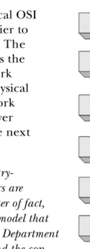
The seven layers in the hierarchical OSI model (Figure 1-1) make it much easier to understand network communication. The application layer at the top represents the actual programs used to access network resources. The bottom layer is the physical layer, through which the actual network data travels. The protocols at each layer work together to package data for the next layer up.
NOTE The OSI model is no more than an industry-recommended standard; protocol developers are not required to follow it exactly. As a matter of fact, the OSI model is not the only networking model that exists—for example, some people prefer the Department of Defense (DoD) model. We’ll work around the con-cepts of the OSI model in this book, so we won’t cover the DoD model here.
[image:27.612.348.438.47.295.2]Let’s take a broad look at the functions of each of the OSI model’s layers as well as some examples of the protocols used in each.
Figure 1-1: A hierarchical view of the seven layers of the OSI model
6 Ch a pt er 1
and desegmentation, and error control, the transport layer makes sure data gets from point to point error free. Because ensuring reliable data trans-portation can be extremely cumbersome, the OSI model devotes an entire layer to it. The transport layer provides its services to both connection-oriented and connectionless protocols. Firewalls and proxy servers operate at this layer.
The Network Layer
The network layer is responsible for routing data between physical networks, and it is one of the most complex OSI layers. It is responsible for the logical addressing of network hosts (for example, through an IP address), and it also handles packet segmentation, protocol identification, and in some cases, error detection. Routers operate at this layer.
The Data Link Layer
The data link layer provides a means of transporting data across a physical network. Its primary purpose is to provide an addressing scheme that can be used to identify physical devices and provide error-checking features to ensure data integrity. Bridges and switches are physical devices that operate at this layer.
The Physical Layer
The physical layer at the bottom of the OSI model is the physical medium through which network data is transferred. This layer defines the physical and electrical nature of all hardware used, including voltages, hubs, network adapters, repeaters, and cabling specifications. The physical layer establishes and terminates connections, provides a means of sharing communication resources, and converts signals from digital to analog and vice versa.
Table 1-1 lists some of the more common protocols used at each individual layer of the OSI model.
l
Protocol Interaction
How does data flow up and down through the OSI model? The initial data transfer on a network begins at the application layer of the transmitting system. Data works its way down the seven layers of the OSI model until it reaches the physical layer, at which point the physical layer of the transmitting system
Table 1-1: Typical Protocols Used in Each Layer of the OSI Model
Layer Protocol
Application HTTP, SMTP, FTP, Telnet
Presentation ASCII, MPEG, JPEG, MIDI
Session NetBIOS, SAP, SDP, NWLink
Transport TCP, UDP, SPX
Network IP, ICMP, ARP, RIP, IPX
P ack et An a lysis a n d N et wor k B asic s 7 sends the data to the receiving system. The receiving system picks up the data at its physical layer, and the data proceeds up the remaining layers of the receiving system to the application layer at the top.
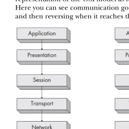
[image:29.612.122.342.221.441.2]Services provided by various protocols at any given level of the OSI model are not redundant. For example, if a protocol at one layer provides a particular service, then no other protocol at any other layer will provide this same service. Protocols at corresponding layers on the sending and receiving computers are complementary. If a protocol on layer seven of the sending computer is responsible for encrypting the data being transmitted, then the corresponding protocol on layer seven of the receiving machine is expected to be responsible for decrypting that data. Figure 1-2 shows a graphical representation of the OSI model as it relates to two communicating clients. Here you can see communication going from top to bottom on one client and then reversing when it reaches the second client.
Figure 1-2: Protocols working at the same layer on both the sending and receiving systems
Each layer in the OSI model is only capable of communicating with the layers directly above and below it. For example, layer two can only send and receive data from layers one and three.
Data Encapsulation
The protocols on different layers communicate with the aid of data
encapsulation. Each layer in the stack is responsible for adding a header or
footer to the data being communicated, and these extra bits of information allow the layers to communicate. For example, when the transport layer receives data from the session layer, it adds its own header information to that data before passing it to the next layer.
Application
Presentation
Session
Transport
Network
Data Link
Physical
Application
Presentation
Session
Transport
Network
Data Link
8 Ch a pt er 1
The Protocol Data Unit
The encapsulation process creates a protocol data unit (PDU), which includes the data being sent and all header or footer information added to it.
As data moves down the OSI model, the PDU changes and grows as header and footer information from various protocols is added to it. The PDU is in its final form once it reaches the physical layer, at which point it is sent to the destination computer. The receiving computer strips the protocol headers and footers from the PDU as the data climbs up the OSI layers. Once the PDU reaches the top layer of the OSI model, only the original data remains.
NOTE The term packet is associated with the term Protocol Data Unit (PDU). When I use the word packet, I am referring to a complete PDU that includes header and footer information from all layers of the OSI model.
Network Hardware
Now it’s time to look at network hardware, where all of the dirty work is done. We’ll focus on just a few of the more common pieces of network hardware— specifically, hubs, switches, and routers.
Hubs
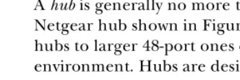
[image:30.612.123.298.400.458.2]A hub is generally no more than a box with multiple RJ-45 ports, like the Netgear hub shown in Figure 1-3. Hubs range from very small four-port hubs to larger 48-port ones designed for rack mounting in a corporate environment. Hubs are designed to connect network devices so that they can communicate.
Figure 1-3: A typical four-port Ethernet hub
P ack et An a lysis a n d N et wor k B asic s 9 Imagine you are sending an email to the employees of a company. The email has the subject line Regarding all marketing staff, but instead of sending it to only those people who work in the marketing department, you send it to every employee in the company. The employees who work in marketing will know it is for them, and they will open it. The other employees, however, will see that it is not for them, and will discard it. You can see how this would result in a lot of unnecessary communication and wasted time—yet this is exactly how a hub functions.
Figure 1-4 provides a graphical display of what is going on here. In this figure, computer A is transmitting data to computer B. However, when com-puter A sends this data, all comcom-puters connected to the hub receive it. Only computer B actually accepts the data; the other computers discard it.
One last note about hubs is that they are only capable of operating in
half-duplex mode—that is, they cannot send and receive data at the same time.
This differentiates them from switches, which are full-duplex devices that can send and receive data synchronously.
[image:31.612.124.295.283.440.2]While you won’t typically see hubs used in most modern or high-density networks (switches are used instead, as discussed below), you should know how hubs work, since they will be very important to packet analysis.
Figure 1-4: The flow of traffic when computer A transmits data to computer B through a hub Switches
The best alternatives to hubs in a production or high-density network are devices called switches. Like a hub, a switch is designed to repeat packets, but it does so very differently; also like a hub, a switch provides a communi-cation path for devices, but it does so more efficiently. Rather than broad-casting data to every individual port, a switch only sends data to the computer for which the data is intended. Physically speaking, a switch looks identical to a hub. As a matter of fact, if the device doesn’t identify itself in writing on the front, you may have trouble knowing exactly which one it is (Figure 1-5).
Computer A
Computer B
Computer C
10 Cha pt er 1
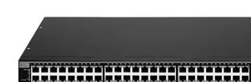
[image:32.612.124.306.128.188.2]Several of the larger switches on the market are manageable via special-ized, vendor-specific software or web interfaces. These switches are commonly referred to as managed switches and provide several features that can be useful in network management. This includes the ability to enable or disable specific ports, view port specifics, make configuration changes, and remotely reboot the switch.
Figure 1-5: A rack-mountable 24-port Ethernet switch
Switches have advanced functionality in handling transmitted packets. In order to be able to communicate directly with specific devices, switches must be able to uniquely identify devices based on their addresses. All this means that they must operate on the data link layer of the OSI model.
Switches store the Layer 2 address of every connected device in a CAM
table, which acts as a kind of traffic cop. When a packet is transmitted, the
switch reads the Layer 2 header information in the packet and, using the CAM table as reference, determines which port(s) to send the packet to. Switches only send packets to specific ports, which greatly reduces network traffic.
[image:32.612.123.294.417.571.2]Figure 1-6 shows a graphical representation of traffic flow through a switch. In this figure, computer A is once again sending data to computer B. In this instance, the computers are connected through a switch that allows computer A to send data directly to computer B without the other devices on the network being aware of this communication. Moreover, multiple conver-sations can happen at the same time.
Figure 1-6: The flow of traffic when computer A transmits data to computer B through a switch
Computer A
Computer B
Computer C
Pa cke t A n al ysis a nd N etw ork Ba sic s 11
Routers
A router is an advanced network device with a much higher level of function-ality than either a switch or a hub. A router can take many shapes and forms, but most have several LED indicator lights on the front and a few network ports on the back, depending on the size of the network (Figure 1-7). Routers operate at Layer 3 of the OSI model, where they are responsible for forwarding
An easy way to illustrate the concept of routing is to think of a neighbor-hood with a network of streets; each street has houses on it, and each house has its own address (Figure 1-8). You live on a street, so you can move among all houses on the street. This is very similar to the operation of a switch that allows communication among all computers on a network segment. To com-municate with a neighbor on another street, however, a person must follow the street signs to that neighbor’s house.
Let’s work through an example of communication across streets. Using Figure 1-8, let’s say I am sitting at 503 Vine Street, and I need to get to 202 Dogwood Lane. In order to do this, I must cross onto Oak Street, and then onto Dogwood Lane. Think of this as crossing network segments. If the device at 192.168.0.3 needs to communicate with the device at 192.168.0.54, it must cross a router to get to the 10.100.1.1 network, then cross the destina-tion network segment’s router before it can get to the destinadestina-tion network segment.
Figure 1-8: Comparison of a routed network to neighborhood streets
packets between two or more net-works. The process routers use to direct the flow of traffic among networks is called routing.
There are several types of routing protocols that dictate how different types of packets are routed to other networks. Routers commonly use Layer 3 addresses (such as IP addresses) to uniquely identify devices on a network.
Figure 1-7: A small router suited for use in a small network
Oak Street
Vine Street
Dogwood Lane 501 502 503 504
505 506 507 508
201 202 203 204
205 206 207 208
12 Cha pt er 1
The size and number of routers on a network will depend on the size and function of that network. Personal and home-office networks may only consist of a small router located at the center of the network, whereas a large corporate network might have several routers spread throughout various departments, all connecting to one large central router or Layer 3 switch. A Layer 3 switch is an advanced type of switch that also has built-in function-ality to act as a router.
As you begin looking at more and more network diagrams, you will come to understand how data flows through these various points. Figure 1-9 shows the layout of a very common form of routed network. In this example, two separate networks are connected via a single router. If a computer on network A wishes to communicate with a computer on network B, the transmitted data must go through the router.
Figure 1-9: The flow of traffic when computer A transmits data to computer X through a router
Traffic Classifications
When considering network traffic, we break it into three main classes: broad-cast, multibroad-cast, and unicast. Each classification has a distinct characteristic that determines how packets in that class are handled by networking hardware.
Broadcast Traffic
A broadcast packet is one that is sent to all ports on a network segment, regard-less of whether that port is a hub, switch, or router. Remember from the section “Hubs” on page 8 that hubs are only capable of broadcast traffic.
Multicast Traffic
Multicast is a means of transmitting a packet from a single source to multiple
destinations simultaneously. The goal of multicast is to make this process as simple as possible by using as little bandwidth as possible. The optimization of this traffic lies in the number of times a stream of data is replicated in order to get to its destination. The exact handling of multicast traffic is highly dependent upon its implementation in individual protocols. The primary method of implementing multicast is by using a special addressing
Computer A
Computer B
Computer C
Computer D
Computer Y
Computer W
Computer X
Computer Z Router
Pa cke t A n al ysis a nd N etw ork Ba sic s 13 scheme that joins the packet recipients to a multicast group; this is how IP multicast works. This addressing scheme ensures that the packets are not capable of being transmitted to computers they are not destined for.
Unicast Traffic
A unicast packet is transmitted from one computer directly to another. The details of how unicast functions depend upon the protocol using it.
Broadcast Domains
Recall that a broadcast packet is one that is sent to every device on a particular segment. In larger networks with multiple hubs or switches connected via different mediums, broadcast packets transmitted from one switch reach all the way to the ports on the other switches on the network, as they are repeated from switch to switch.
The extent to which broadcast packets travel is called the broadcast
domain—it is the network segment where any computer can directly transmit
to another computer without going through a router. Figure 1-10 shows an example of two broadcast domains on a small network. Because each broad-cast domain extends until it reaches the router, broadbroad-cast packets circulate only within this specified broadcast domain.
Figure 1-10: A broadcast domain extends to everything behind the current routed segment.
Our earlier example describing how routing relates to a neighborhood also provides good insight into how broadcast domains work. You can think of a broadcast domain as being like a neighborhood street. If you stand on your front porch and yell, only the people on your street will be able to hear you. If you want to talk to someone on a different street, you have to find a way to speak to that person directly, rather than broadcasting (yelling) from your front porch.
The things you have learned here are the absolute basics of packet analysis. You must understand what is going on at this level of network communication before you can begin troubleshooting network issues. In the next chapter we will build on these concepts and discuss more advanced network communication principles.
Router
2
T A P P I N G I N T O T H E W I R E
We can now move on to the final step of
preparation before we begin to capture live
packets on the network. This last step is to
figure out the most appropriate place to put a
sniffer on the network’s cabling system. This is most
often referred to by packet analysts as getting on the wire, tapping the network, or tapping into the wire. Simply put, this is the process of placing a packet sniffer on a network in the correct physical location.
Unfortunately, sniffing packets is not as simple as plugging in a laptop to a network port and capturing traffic (Figure 2-1). In fact, it is sometimes more difficult to place a packet sniffer on a network’s cabling system than it is to actually analyze the packets.
16 Cha pt er 2
Figure 2-1: Placing your sniffer on the network is sometimes the biggest challenge you will face.
The goal of this chapter is to help you develop an understanding of packet sniffer placement in a variety of different network topologies. We will look at various real-world network setups as we determine the best way to capture packets in hub-, switch-, and router-based environments. As a precursor to understanding sniffer placement, we’ll also take a more in-depth look at promiscuous mode network cards, how they work, and why they are a necessity for packet analysis.
Living Promiscuously
Before you can sniff packets on a network, you need a network interface card (NIC) that supports a promiscuous mode driver. Promiscuous mode is what allows an NIC to view all of the packets crossing the cabling system.
When an NIC is not in promiscuous mode, it generally sees a large amount of broadcast and other traffic that is not addressed to it, which it will drop. When it is in promiscuous mode, it captures everything and passes all traffic it receives to the CPU, basically ignoring the information it finds in a packet’s Layer 2 addresses. Your packet sniffing application grabs those packets to give you a complete and accurate account of all packets on the system.
NOTE Most operating systems (including Windows) will not let you use a network card in promiscuous mode unless you have elevated user privileges. If you cannot obtain these privileges on a system, chances are that you should not be performing any type of packet sniffing on that particular network.
Sniffing Around Hubs
Sniffing on a network that has hubs installed is a dream for any packet analyst. As you learned earlier, traffic sent through a hub is sent to every port connected to that hub. Therefore, to analyze a computer on a hub, all you have to do is plug in a packet sniffer to an empty port on the hub, and you can see all communication to and from all computers connected to that hub. As illustrated in Figure 2-2, your visibility window is limitless when your sniffer is connected to a hub network.
T ap pin g in t o t h e Wi re 17
Figure 2-2: Sniffing on a hub network provides a limitless visibility window.
NOTE The visibility window, as shown in various diagrams throughout this book, shows the devices on the network whose traffic you are able to see with a packet sniffer.
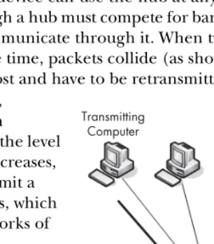
Unfortunately for us, hub-based networks are pretty rare because of the headache they cause network administrators. Hubs tend to slow network traffic because only one device can use the hub at any one time; therefore, a device connected through a hub must compete for bandwidth with the other devices also trying to communicate through it. When two or more devices communicate at the same time, packets collide (as shown in Figure 2-3) and transmitted packets are lost and have to be retransmitted.
ter you’ll learn how to leverage the power of capture and display filters in order to perform your analysis more efficiently.
Computer A
Computer B Computer C
Computer D
Computer E Computer F Sniffer
Visibility Window
As collisions increase, network performance can decrease dramatically. As the level of traffic and collisions increases, devices may have to transmit a packet three or four times, which is why most modern networks of any size use switches.
The only other concern you have to consider when sniffing the traffic of an individual com-puter on a hub network is the volume of traffic in your capture. Since an NIC in promiscuous mode sees all traffic going to and from all devices on a hub, you will have a very large amount of data to sort through, the bulk of which will be irrelevant. In the next
chap-Figure 2-3: Collisions occur on a hub network when two devices transmit at the same time.
Transmitting Computer
Transmitting Computer
Collision
18 Cha pt er 2
Sniffing in a Switched Environment
A switched environment is the most common type of network you will be work-ing on. Switches provide an efficient means of transportwork-ing data via broadcast, unicast, and multicast traffic. (For more on these topics see Chapter 1.) As a bonus, switches allow full-duplex communication, meaning that machines can send and receive data simultaneously through a switch. Unfortunately for packet analysts, switches add a whole new level of complexity to a packet analyst’s job. When you plug in a sniffer to a port on a switch, you can only see broadcast traffic and the traffic transmitted and received by your machine, as shown in Figure 2-4.
Figure 2-4: The visibility window on a switched network is limited to the port you are plugged into.
There are three primary ways to capture traffic from a target device on a switched network: port mirroring, ARP cache poisoning, and hubbing out.
Port Mirroring
Port mirroring, or port spanning as it is often called, is perhaps the easiest way
to capture the traffic from a target device on a switched network. In this type of setup, you must have access to the command-line interface of the switch on which the target computer is located. Also, the switch must support port mirroring and have an empty port into which you can plug your analyzer.
When port mirroring, you log into the command-line interface for your switch and enter a command that forces the switch to copy all traffic on a certain port to another port (Figure 2-5). For instance, to capture the traffic from a device on port three of a switch, you could simply plug your analyzer into port four and mirror port three to port four. This would allow you to see all traffic transmitted and received by your target device.
The exact command you will type to set up port mirroring will vary depending on the manufacturer of the switch you are using. You’ll find a list of common commands in Table 2-1.
Computer A
Computer B Computer C
Computer D
Computer E Computer F Sniffer
T ap pin g in t o t h e Wi re 19
Figure 2-5: Port mirroring allows you to expand your visibility window on a switched network.
When port mirroring, be aware of the throughput of the ports you are mirroring. Some switch manufacturers allow you to mirror multiple ports to one individual port, which may be very useful when analyzing the communi-cation between two or more devices on a single switch. However, consider what will happen using some basic math. For instance, if you have a 24-port switch and you mirror 23 full-duplex 100Mbps ports to one port, you could potentially have 4,600Mbps flowing to that port. This is obviously well beyond the physical threshold of a single port and can cause packet loss or network slowdowns if the traffic reaches a certain level. In these situations switches have been known to completely drop excess packets or “pause” their back-plane, preventing communication altogether. Be sure that this type of situation doesn’t occur when you are when trying to perform your capture.
Hubbing Out
Another very simple way of capturing the traffic through a target device on a switched network is by hubbing out. Hubbing out is a technique in which you localize the target device and your analyzer system on the same network segment by plugging them directly into a hub.
Many people think of hubbing out as cheating, but it’s really a perfect solution in situations where you can’t perform port mirroring but still have physical access to the switch the target device is plugged into.
Table 2-1: Commands Used to Enable Port Mirroring for Different Manufacturers’ Switches
Manufacturer Port Mirroring Command
Cisco set span <source port> <destination port>
Enterasys set port mirroring create <source port> <destination port>
Nortel port-mirroring mode mirror-port <source port> monitor-port
<destination port>
Computer A
Computer B Computer C
Computer D
Computer E Computer F
Sniffer Visibility Window
20 Cha pt er 2
In order to hub out, all you need is a hub and a few network cables. Once you have your hardware, go to the switch the target device resides on and unplug the target from the network. Then plug the target’s network cable into your hub, and plug in another cable connecting your analyzer. Next, connect your hub to the network by plugging in a network cable from it to the network switch. Now you have basically put the target device and your analyzer into the same broadcast domain, and all traffic from your target device will be broadcast so that the analyzer can capture those packets (Figure 2-6).
Figure 2-6: Hubbing out isolates your target device and analyzer on their own broadcast domain.
In most situations, hubbing out will reduce the duplex of the target device from full to half. While this method isn’t the cleanest way to tap into the wire, it’s sometimes your only option when a switch does not support port mirroring.
NOTE As a reminder, it is usually a nice gesture to alert the user of the device that you will be unplugging it, especially if that user happens to be the company CEO!
When hubbing out, be sure that you’re using a true hub and not a falsely labeled switch. Several networking hardware vendors have a bad habit of marketing and selling a device as a hub when it actually functions as a low-level switch. If you aren’t working with a proven, tested hub, you will only see your own traffic, not that of the target device. When you find a hub, test it to make sure it really is a hub—if it is, it’s a keeper! The best way to determine whether or not the device you are using is a true hub is to hook a pair of computers up to it and see if one can sniff the other’s traffic. If so, you have a true hub in your possession.
ARP Cache Poisoning
Recall from Chapter 1 that the two main types of packet addressing are at Layers 2 and 3 of the OSI model. These Layer 2 addresses, or MAC addresses, are used in conjunction with whichever Layer 3 addressing system you are
Computer A
Computer B Computer C
Computer D
Computer E Computer F Sniffer
Visibility Window
T ap pin g in t o t h e Wi re 21 using. In the case of this book (and the industry standard), I refer to the Layer 3 addressing system as the Internet Protocol (IP) addressing system.
All devices on a network communicate with each other on Layer 3 using IP addresses. Because switches operate on Layer 2 of the OSI model, they must be able to translate Layer 2 MAC addresses into Layer 3 IP addresses and vice versa in order to be able to forward traffic to the appropriate device. This translation process is done through a Layer 3 protocol known as the Address
Resolution Protocol (ARP).
When one computer needs to send data to another, it sends an ARP request to the switch it is connected to. The switch then sends an ARP broad-cast packet to all of the computers connected to it, asking each computer it reaches if it is has the IP address of the computer trying to be reached. When the destination computer sees this packet, it identifies itself to the switch by giving its MAC address. The switch now has a route established to that destination computer, and any device that wishes to communicate with the destination computer can use the route. This newly obtained information is stored in the switch’s ARP cache so that the switch does not have to send a new ARP broadcast every time it needs to send data to a computer.
ARP cache poisoning is a more advanced form of tapping into the wire on a switched network. It is commonly used by hackers to send falsely addressed packets to client systems in order to intercept certain traffic or cause denial of service (DoS) attacks on a target, but ARP cache poisoning can still serve as a legitimate way to capture the packets of a target machine on a switched network.
ARP cache poisoning, sometimes referred to as ARP spoofing, is the process
of sending ARP messages to an Ethernet switch or router with fake MAC (Layer 2) addresses in order to intercept the traffic of another computer (Figure 2-7).
Figure 2-7: ARP cache poisoning allows you to intercept the traffic of your target computer.
Using Cain & Abel
When attempting to poison the ARP cache, the first step is to download the required tools and collect some necessary information. We’ll use the popular security tool Cain & Abel from Oxid.it (http://www.oxid.it). Go ahead and install it now.
Normal Traffic Pattern Target
Computer Switch Router
Sniffer
Poisoned ARP Cache
Switch Router
Sniffer Target
22 Cha pt er 2
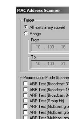
Once you have installed the Cain & Abel software, you need to collect some additional information including the IP addresses of your analyzer system, the remote system you wish to capture the traffic from, and the router that the remote system is downstream from.
When you first open Cain & Abel, you will notice a series of tabs near the top of the window. (ARP cache poisoning is only one of a variety of Cain & Abel’s features.) For our purposes, we’ll be working in the Sniffer tab. When you click this tab, you will see an empty table (Figure 2-8).
Figure 2-8: The Sniffer tab in the Cain & Abel main window
In order to fill this table you will need to activate the program’s built-in sniffer and scan your network for hosts. To do so, follow these steps:
1. Click the second icon on the toolbar, which resembles a network card. The first time you do this you will be asked to select the interface you wish to sniff. This interface should be the one that is connected to the network you will be performing your ARP cache poisoning on. 2. Once you’ve selected this interface, click OK to activate Cain & Abel’s
built-in sniffer.
3. To build a list of available hosts on your network, click the icon that resembles a plus (+) symbol, and click OK (Figure 2-9).
The once-empty grid should now be filled with a list of all the hosts on your attached network, along with their MAC addresses, IP addresses, and vendor identifying information. This is the list you will work from when setting up your ARP cache poisoning.
T ap pin g in t o t h e Wi re 23
Figure 2-9: The Cain & Abel network discovery tool
Once in the APR window, you are presented with two empty tables: an upper and a lower one. Once you set them up, the upper table will show the devices involved in your ARP cache poisoning, and the lower table will show all communication between your poisoned machines.
To set up your poisoning, follow these steps:
1. Click the icon resembling the plus (+) symbol on the program’s standard toolbar. The window that appears has two selection columns side by side.
2. On the left side, you will see a list of all available hosts on your network. Click the IP address of the target computer whose traffic you wish to sniff. This will result in the right window showing a list of all hosts in the network, omitting the target machine’s IP address.
3. In the right window, click the IP address of the router that is directly upstream of the target machine, and click OK (Figure 2-10). The IP addresses of both devices should now be listed in the upper table in the main application window.
4. To complete the process, click the yellow-and-black radiation symbol on the standard toolbar. This will activate Cain & Abel’s ARP cache poison-ing features and allow your analyzpoison-ing system to be the middleman for all communications between the target system and its upstream router.
24 Cha pt er 2
Figure 2-10: Selecting the devices for which you wish to enable ARP cache poisoning
NOTE As a final note on ARP cache poisoning, you should be very aware of the roles of the systems you implement this process for. For instance, do not use this technique when the target device is something with very high network utilization, such as a fileserver with a 1Gbps link to the network (especially if your analyzer system only provides a 100Mbps link). When you perform this rerouting of traffic, all traffic transmitted and received by the target system must first go through your analyzer system, therefore making your analyzer the bottleneck in the communication process. This can create a DoS-type effect on the machine you are analyzing, which will result in degraded network performance and faulty analysis data.
Sniffing in a Routed Environment
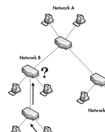
All of the techniques for tapping into the wire on a switched network are avail-able on routed networks, as well. The only major consideration when dealing with routed environments is the importance of sniffer placement when you are troubleshooting a problem that spans multiple network segments.
As you learned earlier, a device’s broadcast domain extends until it reaches a router. At this point the traffic is handed off to the next upstream router and you lose communication with the packets being transmitted until you receive an acknowledgment of their receipt. In situations like this where data must traverse multiple routers, it is important to analyze the traffic on all sides of the router.
T ap pin g in t o t h e Wi re 25
Figure 2-11: A computer on network D can’t communicate with one on network A.
Your gut might tell you to sniff the traffic of a device on segment D. When you do, you can clearly see data being transmitted to segment A, but without traffic acknowledgments. When sniffing the next upstream network segment to find the source of the problem, you find that traffic is dropped by the router of network B. Eventually this leads you to a router configuration problem that, when corrected, solves your larger dilemma. This is a prime example of why it is often necessary to sniff the traffic of multiple devices on multiple segments in order to pinpoint a problem.
Network Maps
In our brief discussion about network placement, we have already looked at several different network maps. A network map, or network diagram, is a diagram showing all technical resources on a network and how they are connected.
There is no better way to determine the placement of your packet sniffer than to be able to visualize the network clearly. If you have a network map available to you, I would highly recommend keeping it handy, as it will become a valuable asset in the troubleshooting and analysis process. You may even want to make a detailed network map of your own network. Remember, sometimes half the battle in troubleshooting is pinpointing the problem.
Network A
Network B
Network C
3
I N T R O D U C T I O N T O W I R E S H A R K
There are several different packet sniffing
applications available for performing
net-work analysis, but we’ll be using Wireshark
throughout this book. This chapter discusses the
history of Wireshark, as well as its benefits, installation,
and basic use.
A Brief History of Wireshark
Wireshark has a very rich history. Gerald Combs, a computer science graduate of the University of Missouri at Kansas City, originally developed it out of necessity. The very first version of Combs’ application, called Ethereal, was released in 1998 under the GNU Public License (GPL).