i
WIRELESS SECURITY SYSTEM
UKASYAH BIN MAHAMOD
This Report is submitted in partial fulfillment of the requirements for the award of Bachelor Electronic Engineering (Computer Engineering) with Honours
Faculty of Electronic Engineering and Computer Engineering Universiti Teknikal Malaysia Melaka
Tajuk Pr Sesi Pengajia
Saya …… mengaku me syarat kegun 1. Laporan 2. Perpusta 3. Perpusta pengajia 4. Sila tand
Alamat Teta
T
FAKU
rojek : W
an : 20
UKASYAH B (HURUF embenarkan La naan seperti ber n adalah hakmi akaan dibenark akaan dibenark an tinggi. dakan ( √ ) :
SULIT*
TERHAD*
TIDAK TER
______________ (TANDATANGA
ap: NO 9 JALAN 4 BANDAR BA 43650,SELAN Tarikh: ………… UNIVE ULTI KEJURUT B WIRELESS SE 008/2009 BIN MAHAMO F BESAR)
aporan Projek S rikut:
ilik Universiti T kan membuat s kan membuat s
(Me kep RA (Me org RHAD _____________ AN PENULIS) 4/7F, ARU BANGI, NGOR D.E. ……….. ERSTI TEKNI ERAAN ELEKT ORANG PENGE PROJEK S ECURITY SY OD……… Sarjana Muda Teknikal Mala salinan untuk tu salinan laporan
engandungi mak pentingan Malay AHSIA RASMI 1
engandungi mak ganisasi/badan di
IKAL MALA TRONIK DAN K
ESAHAN STATU
SARJANA M
YSTEM
ini disimpan d
aysia Melaka. ujuan pengajia n ini sebagai ba
klumat yang berd ysia seperti yang
1972)
klumat terhad ya i mana penyelidi
D
____________ (COP DAN TA
Tarikh: AYSIA MELA KEJURUTERA US LAPORAN MUDA II di Perpustakaan an sahaja. ahan pertukaran darjah keselama termaktub di da
ang telah ditentuk ikan dijalankan) Disahkan oleh: _______________ ANDATANGAN P ……… KA AAN KOMPUTE
n dengan syarat
n antara institu
iii
”I hereby declare this report is result of my own work expect for quotes as cited in the reference.”
iv
”I hereby declare that I have read this report and in my opinion this report is sufficient in terms of the scope and quality for the award of Bachelor of Electronic Engineering
(Computer Engineering) with Honours.“
v
vi
ACKNOWLEDGEMENT
In a personal note, first and foremost, I would like to thank Allah the Almighty for giving me the opportunity to continue my life and studies up until now and forever.
Professionally, I want to thank the faculty of electronic engineering and computer engineering for giving me this precious moment of my life to be accepted in this faculty and learn many new things. Next, I would like to express my profound gratitude to my supervisor, Mr Masrullizam bin Mat Ibrahim for the invaluable support, encouragement, supervision and useful suggestions throughout this project, my friends in BENC S1 for all the great moment through this process.
Next I would like to thank all that are involved directly or indirectly in helping and assisting me out in anyway. Finally I would also want to thank my parents, family members and friends for always being there for me. All your love and support really makes you all very special in my heart.
UKASYAH BIN MAHAMOD
Faculty of Electronic Engineering and Computer Engineering,
vii
ABSTRACT
viii
ABSTRAK
ix
TABLE OF CONTENTS
CONTENT PAGE
PROJECT TITLE i
RECOMMENDATORY ii
DEDICATION v
ACKNOWLEDGEMENT vi
ABSTRACT vii
ABSTRAK viii
TABLE OF CONTENT ix
LIST OF TABLE xii
LIST OF FIGURE xiii
LIST OF ABBREVIATION xv
CHAPTER 1: INTRODUCTION
1.1 Introduction to project 1
1.2 Objective of project 2
1.3 Problem statement 2
1.4 Scope of project 3
1.4.1 Hardware development 3
1.4.2 Software development 3
1.4.3 Limitation of project 4 1.5 Overview of remaining chapters 4
CHAPTER 2: LITERATURE REVIEW
2.1 Introduction 6
x
2.3 Wireless 8
2.4 Wireless security system 8
2.5 Sensor 9
2.5.1 Door sensor 9
2.5.1.1 Magnetic reed switch ‘contacts’ 9 2.5.1.2 Infrared (IR) sensor 10
2.5.2 Motion sensor 11
2.5.2.1 Ultrasonic motion sensor 11 2.5.2.2 Passive Infrared sensor (PIR) 12
2.5.2.3 Microwave motion sensor 13
2.6 Wireless 14
2.6.1 Radio frequency module 315MHz 14 2.6.2 XBee High Radio Frequency Module 15 2.6.3 Bluetooth Radio module 16
2.7 Microcontroller 16F877A 17
2.8 Encoder and Decoder 18
2.8.1 Encoder 18
2.8.2 Decoder 19
2.9 Liquid Crystal Display (LCD) 20
2.10 Speaker and Buzzer 21
2.11 Charging Circuit 22
CHAPTER 3: METODOLOGY
3.1 Overview of system 24
3.2 Hardware 25
3.2.1 Sensor system 25
3.2.2 Wireless system 27
3.2.3 Alarm system 28
3.2.4 Charging circuit 29
xi
3.3.1 CCS Compiler 30
3.3.2 Proteus Virtual System Modeling (VSM) Schematics Simulation 31
3.3.3 WinPic Programmer 32
CHAPTER 4: RESULT AND DISCUSSION
4.1 4.1 Introduction 33
4.2 Software and simulation result 34
4.2.1 Simulation result 34
4.2.2 Source code result 36
4.3 Hardware result 39
4.3.1 Board design and board etching 39
4.3.2 The model design 40
4.3.3 Sensor design 41
4.3.4 Range of transmitter and receiver result 42
4.3.5 Output of decoder 43
4.3.6 Signal output of antenna 44
4.3.7 Sensor result 45
4.3.7.1 IR sensor 45
4.3.7.2 Magnetic sensor 46
4.3.7.3 Shock sensor 46
4.3.8 Wireless length Result 47
CHAPTER 5: CONCLUSION AND SUGGESTIONS
5.1 Introduction 48
5.2 Conclusion 48
5.3 Suggestion 49
REFERENCE 50
xii
LIST OF TABLE
NO TITLE PAGE
4.1 Result on bread board 42
4.2 Result on etching board 42
4.3 IR range result 45
4.4 Magnetic sensor position result 46
xiii
LIST OF FIGURE
NO TITLE PAGE
2.1 Overview of project 7
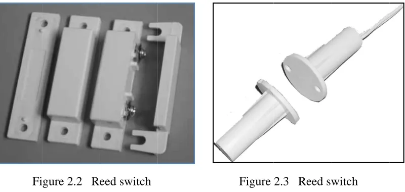
2.2 Reed switch 9
2.3 Reed switch 9
2.4 IR sensor transmitter and receiver 10
2.5 Circuit diagram 10
2.6 Ultrasonic motion detection 11 2.7 Ultrasonic motion detection in a covered case 11
2.8 PIR sensor 12
2.9 PIR sensor in closed case 12 2.10 Inside a microwave sensor 13
2.11 Transmitter 14
2.12 Receiver 14
2.13 Xbee model 15
2.14 Bluetooth radio module 16
2.15 Microcontroller 16F877A 17
2.16 Encoder model HT12E 18
2.17 decoder model HT12D 19
2.18 2 x 16 Characters LCD Display 20 2.19 2 x 16 Characters Graphic LCD Display 20
2.20 Speaker 21
2.21 Buzzer 21
2.22 LM3647 22
3.1 Overview of the system 24
xiv
3.3 IR sensor circuit 26
3.4 Wireless system 27
3.5 Alarm system circuit 28
3.6 Charging circuit 29
3.7 Screenshot of CCS Compiler 30
3.8 Screenshot of Proteus 31
3.9 Screenshot of WinPic Programmer 32
4.1 Simulation result 35
4.2 Source Code for microcontroller at alarm system 36
4.3 Output 1 37
4.4 Output 2 37
4.5 Output 3 37
4.6 Output 4 37
4.7 Output 5 37
4.8 Output 6 37
4.9 Source Code for sensor 1 38
4.10 Source Code for sensor 2 38
4.11 After etching process 39
4.12 Monitoring system design 40
4.13 Alarm system 1 design 40
4.14 Alarm system 2 design 40
4.15 IR sensor design 41
4.16 Magnetic sensor design 41
4.17 Shock sensor design 41
4.18 Output of decoder 43
4.19 Output of antenna 44
4.20 IR sensor position 1 45
xv
LIST OF ABBREVIATION
RF - Radio Frequency LCD - Liquid Crystal Display
PIC - Peripheral Interface Controller PC - Personal Computer
UART - Universal Asynchronous Receiver Transmitter USB - Universal Serial Bus
GUI - Graphical User Interface IR - Infrared
PIR - Passive Infrared Sensor
FHSS - Frequency Hopping Spread Spectrum CPU - Central Processing Unit
RAM - Random Access Memory HEX - Hexadecimal
USART - Universal Synchronous Asynchronous Transmitter Receiver IC - Integrated circuit
CMOS - Complementary metal–oxide–semiconductor Li-Ion - Lithium-Ion
Ni-MH - Nickel-Metal Hydride NI-Cd - Nickel-Cadmium
ADC - Analog to digital converter CLR - Clear
1
CHAPTER 1
INTRODUCTION
1.1 Introduction to project
It has always been a necessary, in one way or another to guard and protect our homes and property. Referring to Vivian Capel [1], today, with modern consumer society churning out new technology goods at frightening pace, the range of stolen items grows ever larger. Many people have suffered the trauma of crime in their neighborhoods and at top of the list is burglary. This lost bring a sense of instability and uncertainty into the lives of those most affected.
2
system in a way but the method of connecting the alarm system is slightly different. The wireless security system gives a new dimension to security system development [3].
The security alarm is wireless equipment in the true sense. Its installation does not require you to dig holes in the walls or do drilling as it does not need any set of wires for data communication totally relies on radio frequency (RF) waves for data transfer. This wireless character not only makes its installation easy but also increases the efficiency of working. As it has been observed that whenever a criminal burgles in he tries to trace the wires and find out if any security alarm is installed so that he can destroy or damage it before committing any crime. Since your wireless security alarm does not require any wires, it only eases its handling and installation but allows you to hide or camouflage it in dummy boxes as this way it would be highly difficult for criminals to locate alarm[4][5].
1.2 Objective of project
This project consists of several objectives that to accomplish at the end of this project. The objectives are:
i. Create a security system that is more affordable for users. ii. Create a wireless and portable security system.
iii. Flexible and easier installation device.
1.3 Problem Statement
3
So the main objective of the project is to create a security system that is more affordable for users at any level in the society. The important part is to create a wireless and portable security system for users to benefit. To add more value to the project, it is design so it can be flexible and easier installation for user usage.
1.4 Scope of project
The scope of project is done so the objective of the project can be archive. The wireless security system is consisting of two parts that is software development and hardware development.
1.4.1 Hardware development
The hardware development is consists components that will be used to build the design the project. There are 3 parts main part in this system that is the sensor system, the wireless system and the alarm system. The sensor system includes door sensor and motion sensor. Components that will be used for the door sensor is shock and magnetic sensor. While components for the motion sensor is infrared sensor and PIR sensor. Next the RF module 433MHz will be used for the wireless module. Finally the third part in hardware development is the alarm system that is consists of LCD display and a buzzer.
1.4.2 Software development
4
1.4.3 Limitation of project
There is some limitation that has been recognized to the project. Firstly the range of the security devices in only up to 50 meter. Next the device only can use for house usage and small office purpose because of the range limitation.
1.5 Overview of Remaining Chapters
This report consists of five chapters: the chapter respectively is Introduction, Literature Review, Methodology, result and analysis, conclusion and discussion.
In chapter 1 Introduction, it will be discussed about project objective, project background, problem statement, scope of work, and overview of remaining chapters.
In chapter 2 Literature Review, it will be discussed on reviews of some references from previous project, journal, article, books and datasheet. All the materials were useful to ensure the success of this project.
In chapter 3 Methodology, it will be discussed on the flow of this project started and how it will be functional. There are several flow chart of the program of project to explain the process of the circuit within combining hardware and software until project archive the project objectives.
5
6
CHAPTER 2
LITERATURE REVIEW
2.1 Introduction
This chapter reasons to review and discuss some of references from previous projects, journals, books and datasheet. All this information was collected from the different sources such as library, internet and product manual. The useful data of this project will be discussed on this chapter.
2.2 Previous Project
7
The reed switches and magnets are used as a door sensor and are connected near the garage doors, and it detects the open/closed. The Atmel Attiny45 microcontroller fits in nicely with design because of its small size, low pin count and low cost. This controller has a powerful serial interface feature that can be set up as a UART and requires interface for the Zigbee wireless module. When a door opens or closes, the Attiny45 sends a message wirelessly to the PC interface.
The PC interface consists of a standard Windows XP PC and a USB adapter that includes a Zigbee wireless transceiver. The PC runs an application that receives messages from the door sensor and graphically shows the state of the security system by changing its icon in the system tray. Using the PC’s clock, an alert sound is played if the door is open during the middle of the night. The application runs in the “background” while the PC is used for other purposes.
[image:22.612.116.538.362.489.2]There are two pieces of hardware, the Door Sensor and the PC Wireless Interface. In the Door Sensor, an Atmel ATtiny45 monitors the reed switches and sends the switch status through a Zigbee wireless transceiver to the PC Wireless Interface. The PC Wireless interface passes the message up to a GUI application running on the PC. Figure 2.1 shows the overview of the project.
8
2.3 Wireless
Wireless communication is transferring sets of information over a distance without the use of electrical conductors or wires [8]. The distances involved may be short like a few meters as in television remote control or very long like thousands or even millions of kilometers for radio communications. When the context is clear the term is often simply shortened to "wireless". Wireless communications is generally considered to be a branch of telecommunications. Wireless operations permits services, such as long range communications, that are impossible or impractical to implement with the use of wires. The term is commonly used in the telecommunications industry to refer to telecommunications systems like Radio Frequency that will be used as a medium of connection between components in the wireless security system.
2.4 Wireless security system
2 c v i 2 t i B 2 r p 2.5 Sens At th chosen to d various prin is installed.
2.5.1 Door
One the main acc intruder to b sensors that Below are so
2.5.1.1Mag
The reed switch pair of matc Fi
sor
he forefront detect the pr nciples and it
r Sensor
of the most cess for us t brake in. Tha
are suitable ome of the s
gnetic reed s
most comm is an electri ching perma igure 2.2 Re
t of any sec resence or t t is importan
t important p to go in and
at is why sen to use as do sensors suitab
switch ‘cont
monest and s cal switch o anent magne eed switch
curity system the passage nt to which
parts of a bu out of a bui nsors must b oor sensor de ble for the d
tacts’
simple senso operated by a t, fitted mai
m is a senso of an intru sensor is ch
uilding is th ilding. The d be installed t epending on door.
[image:24.612.130.530.439.629.2]or of all is t an applied m inly to doors Figure
or that has uder. These hosen at each
e door. The door is also
to the door. user needs a
the humble magnetic fiel s and somet 2.3 Reed sw
been specif devices wor h point the s
door is the one an acce
There are ce and requirem