i
LIGHT GUIDED PATH TRACKER ROBOT
HUZAIFA BIN MUSA
This Report is submitted in Partial Fulfillment of Requirements for the Degree of Bachelor in Mechatronic Engineering
FACULTY OF ELECTRICAL ENGINEERING UNIVERSITI TEKNIKAL MALAYSIA MELAKA
ii
ACKNOWLEDGEMENT
In The Name of Allah the Most Merciful and Most Compassionate
There are many individuals that had contributed to the success of this Final Year Project
(FYP). First and foremost, our gratitude goes to Al-Mighty for bestowing the strength and
patience in completing this report. My warmest gratitude goes to my supervisor, Mr. Prof.
Madya Dr. Ismadi bin Bugis for giving the most beneficial guidance and assistance to me in
finishing my FYP.
My in most appreciation goes to Mr. Mohd Shahrieel bin Mohd Aras, Mr. Hyreil Anuar bin
Kasdirin and Mr. Zamani bin Md Sani for giving me a good comments and developing critics
during FYP seminar.
Last but not least, I would like to express my deepest gratitude to my beloved mother and
father, as well as our family members and everyone who has involved directly or indirectly for
their moral support and understanding. It‟s not an easy way to me for survive without their
helping.
iii
ABSTRACT
This project basically is to build a mobile robot that is able to sense light and move
toward the light source as an attraction of a robot. At the end of this project, a Light Guided
Path Tracker Robot was build. The robot is operated without using any external controller to
control a movement of the robot. Cadmium Sulfide (CdS) photocells are used as a sensors for
the robot that will detect the light source and controlled by PIC 16F877A as a controller. The
sensor acts as radar to detect light illuminating from surrounding and will produce a certain
differential potential. These potential differentials which is an analog signal processed by a
microcontroller as a digital value, and a microcontroller will sending an instruction to the
iv
ABSTRAK
Projek ini pada asasnya adalah untuk membina sebuah robot mobil yang berkebolehan
untuk mengesan cahaya dan akan bergerak ke arah sumber cahaya tersebut. Projek ini akan
menghasilkan sebuah robot pintar dengan nama yang diberikan sebagai Light Guided Path
Tracker Robot. Robot ini akan dikendalikan tanpa mengunakan sebarang alat kawalan luar
untuk mengawal arah pergerakannya. Perintang peka cahaya (CdS photocell ) akan digunakan
sebagai deria kepada robot yang akan mengesan cahaya dan akan dikawal dengan
menggunakan pengawal mikro PIC 16F877A. Tindak balas yang diberikan oleh perintang
peka cahaya terhadap pencahayaan sekeliling akan menghasilkan satu bezaupaya yang
tertentu. Bezaupaya tersebut seterusnya akan diproses oleh pengawal micro sebagai suatu nilai
digital seterusnya menghantar arahan ke bahagian litar keluaran yang terdiri daripada system
v
“I hereby declared that I have read through this report entitle “Light Guided Path Tracker
Robot” and found that it has comply the partial fulfillment for awarding the degree of
Bachelor of Mechatronic Engineering”
Signature : ……….
Supervisor‟s Name : Prof. Madya Dr. Ismadi bin Bugis
vi
“I hereby declared that this report entitle “Light Guided Path Tracker Robot” is the
result of my own research except as cited in the references. The report has not been
accepted for any degree and is not concurrently submitted in candidature of any other
degree.”
Signature : ………
Name : Huzaifa bin Musa
vii
TABLE OF CONTENTS
CHAPTER TITLE PAGE
ACKNOWLEDMENT ii
ABSTRACT iii
DECLARATION v
TABLE OF CONTENTS vii
LIST OF TABLE x
LIST OF FIGURES xi
LIST OF SYMBOLS xiii
LIST OF APPENDICES xiv
1 INTRODUCTION 1
1.1 Project Background 1
1.2 Problem Statement 2
1.3 Objective of Project 2
1.4 Scope of Project 3
2 LITERATURE REVIEW 4
2.1 Literature 1 : Autonomous Light Finder Robot 4
2.2 Literature 2 : Light Rover 6
2.3 Literature 3 : Veroboard Bot 8
2.4 Literature 4 : Light Seeking Robot 10
2.5 Literature 5 : Robot Mobil Pengesan Cahaya 11
3 THEORY AND BACKGROUND 12
3.1 PIC Microcontroller 12
3.2 Light Sensor 15
3.3 DC Motor 20
3.3.1 Operating Voltage of DC Motor 21
3.3.2 Operating Current of DC Motor 21
3.3.3 Speed of DC Motor 23
viii
3.3.5 Power of DC Motor 23
3.3.6 Gear and Speed 24
3.4 H-Bridge Circuit (L298) 24
3.5 Pulse Width Modulation in Microcontroller 26
4 METHODOLOGY 28
4.1 Overview of the Project Development 28
4.2 Designing a Light Guided Path Tracker Robot 32
4.3 Software Implementation 34
4.3.1 Algorithm and Programming in MicroC 34
4.3.1.1 Processing Explanation of Main Program 36
4.4 Research Methodology 41
4.4.1 Selecting the Fixed Resistor ( Rf ) Value for Light
Sensing Circuit. 41
4.4.2 Controlling the Speed of Robot Based on the
Intensity of Light 44
4.4.3 Evaluate the DC Motor Performance on L298 Dual
H-Bridge Driver 48
5 RESULT, ANALYSIS AND DISCUSSION 52
5.1 Introduction 52
5.2 Experiment 1 : Selecting the fixed resistor for light sensing circuit
52
5.2.1 Objective 52
5.2.2 Equipment Required 52
5.2.3 Procedures 53
5.2.4 Result and Discussion 55
5.2.5 Conclusion 59
5.3 Experiment 2 : Controlling the speed of robot based on the intensity of light
60
5.3.1 Objective 60
5.3.2 Equipment Required 60
5.3.3 Procedures 60
5.3.4 Result and Discussion 62
5.3.5 Conclusion 64
5.4 Experiment 3 : Evaluate the performance of DC motor on L298 dual H-bridge driver
ix
5.4.1 Objective 65
5.4.2 Equipment Required 65
5.4.3 Procedures 65
5.4.4 Result and Discussion 67
5.4.5 Conclusion 72
6 CONCLUSION AND RECOMENDATION 73
5.1 Conclusion 73
5.2 Recommendation 74
REFERENCES 75
x
LIST OF TABLES
CHAPTER TABLE PAGE
3 Table 3.1 : Truth Table for Controlling DC Motor 26
4 Table 4.1 : Resistance in the shade (R_dark) and Resistance
in the (R_bright)
42
Table 4.2 : Comparison Between Theoretical Output Voltage and Real Time Measurement Output Voltage
43
Table 4.3 : Comparison Between Light Intensity Value and Speed
47
Table 4.4 : Voltage Comparison Between Left Motor and Right Motor
49
Table 4.5 : Current Comparison Between Left Motor and Right Motor
51
5 Table 5.1 : Comparison Between Resistance in the Shade and
Resistance When Exposed Directly to the Light
55
Table 5.2 : Light Sensing Circuit Measurement Result 56
Table 5.3 : Average Resistance Value in Dark and When Exposed Directly to Light
57
Table 5.4 : Comparison Between Resistor Value and Voltage Output
57
Table 5.5 : Comparison Between Theoretical Result and Real Time Measurement Result
58
Table 5.6 : Comparison Between Light Intensity Value and Speed
62
Table 5.7 : Connection for Microcontroller and L298 66
Table 5.8 : Voltage Measurement Result 67
[image:10.612.83.546.82.678.2] [image:10.612.85.538.91.648.2]xi
LIST OF FIGURES
CHAPTER FIGURE PAGE
2 Figure 2.1 : The Autonomous Light Finder Robot 5
Figure 2.2 : Light Rover 6
Figure 2.3 : Differential Steering 9
3 Figure 3.1 : PIC16F877A Microcontroller Pin Configuration 13
Figure 3.2 : Photoresistor or Light Dependent Resistor (LDR) Picture
15
Figure 3.3 : The Cadmium Sulphide Track of Photoresistor 16
Figure 3.4 : The Voltage Divider Circuit 16
Figure 3.5 : Voltage Increases With Light Circuit 17
Figure 3.6 : Voltage Decreases With Light Circuit 18
Figure 3.7 : Light Sensing Circuit for One Sensor 18
Figure 3.8 : Small DC Geared Motor 20
Figure 3.9 : Model of Simple DC Motor 21
Figure 3.10 : Bi-Direction of DC Motor Speed Control 25
4 Figure 4.1 : Simulation Process by Using Proteus 7.2 Software 29
Figure 4.2 : MicroC V8.1 30
Figure 4.3 : PIC Programmer Hardware 31
Figure 4.4 : Sample Robot Design by Using SolidWork 2007 Software
32
Figure 4.5 : Light Guided Path Tracker Robot 33
Figure 4.6 : Arrangement of the Sensors for the Robot 34
Figure 4.7 : Flowchart of Microcontroller Main Program 35
Figure 4.8 : Result of A/D Conversion in Two A/D Registers 36
Figure 4.9 : The ADCON1 Register 37
Figure 4.10 : The A/D Port Configuration Bits 37
Figure 4.11 : PWM Output 38
Figure 4.12 : Simplified Block Diagram of the CCP Module in PWM Mode
[image:11.612.483.545.91.704.2]39
xii
Figure 4.14 : Simulation Diagram 45
Figure 4.15 : Experiment Setup Diagram 46
Figure 4.16 : Motor Driver Board Layout 48
5 Figure 5.1 : Measuring the Resistance of Photoresistor by
Using a Multi-meter
53
Figure 5.2 : Light Sensing Test Circuit 54
Figure 5.3 : Graph Theoretical Output Voltage Versus Measurement Output Voltage
59
Figure 5.4 : Line Marking Setup 60
Figure 5.5 : Graph Light Intensity Versus Distance of the Light Source
63
Figure 5.6 : Graph Light Intensity Versus Speed 63
Figure 5.7 : DC Motor Test Coding 65
Figure 5.8 : Output Voltage Versus CCP1 ( PWM1) 69
Figure 5.9 : Output Voltage Versus CCP2 ( PWM2) 69
Figure 5.10 : L298 Block Diagram and Red Box Show the BJT Inside the L298
xiii
LIST OF SYMBOLS
- Magnetic Flux
- Armature Current
- Voltage Output
- Armature Resistor
- Electro Magnetic Field (EMF)
K - Motor Constant
n - Rotational Speed (rpm)
- Motor Speed
- Total Voltage
- Electrical Output Torque
D - Duty Ratio
- Time ON switch
- Frequency
- Voltage Input
- Output Power
- Fixed Resistor
rpm - Revolution Per Minutes
PWM - Pulse Width Modulation
LDR - Light Dependent Resistor
xiv
LIST OF APPENDICES
APPENDIX TITLE PAGE
A PIC Instruction Set For Experiment 2 : Controlling the
speed of robot based on the intensity of light
76
B Full Instruction Set of Light Guided Path Tracker Robot 78
C Light Guided Path Tracker Robot Design By Using
Solidwork 2008
80
CHAPTER 1
INTRODUCTION
In this section, an introduction towards project will be briefed. This chapter consists of
background, problem statement and scope of the project.
1.1 Project Background
Light Guided Path Tracker Robot is a mobile robot that similar with Light Seeking
Robot, Light Finding Robot, Light Sensing Robot, Light Chasing Robot, Light Tracking
Robot and Light Following Robot. As the name suggests, it able to directs itself towards the
visible light as an attraction point. A user can direct shine flashlight to robot sensors and as a
respond, the robot will follow the source of light. Its speed is dependent upon the intensity of
the light detected. The higher intensity of the light, the faster movement of the robot. To
accomplish this project, it is divided on three parts which are mechanical part, electronic part
and software part.
In the mechanical part, the base of the mobile robot will be designed and fabricated. In
the electrical part, there are three different circuit need to design and construct which are light
sensing circuit, PIC microcontroller board and motor controller circuit. For software part, the
2
1.2 Problem Statement
Most of the light sensing robot that has already built can only functioning well at dark
environment. Some robot is designed with 3 sensors, a center, a left and a right. And some
other are designed with 2 sensors, a left and a right. The movement of a robot created is also
limited because the robot can only move forward, turn right and turn left, and the robot do not
have ability to go backward, reverse left and reversed right. Some robot does no use
microcontroller as its mind and the robot speed cannot be controlled.
The purpose of this project is to overcome all the problems faced on the light sensing
robot that had been mentioned previously.
1.3 Objective of Project
The main objective of this project is to build the robot that is able to sense and follow
the visible light by using PIC microcontroller as the main controller. To ensure the project
progresses smoothly, there are some objectives that need to be achieved:
a) To do simulation and build the electronic circuit.
b) To design and establish the mechanical structure of robot.
c) To achieve multi direction motion.
d) To control the speed of robot by using the intensity of the light.
e) To measure the resistance value of Light Dependent Resistor (LDR) when the LDR is
exposed to the light and direction of the robot will be determined from resultant of the
3
1.4 Scope of Project
To understand the function of components for the robot, there are some theories about
project background research and literature review that must be studied. The components such
as PIC microcontroller, light dependent resistor (LDR) sensor and motor will be considered as
main component in this project. Light Guided Path Tracker Robot uses a microcontroller for
processing the sensor readings and responds by controlling the motors. The microcontroller
that will be used in this project is PIC 16F877A, this is due to its internal ADC which is
important in converting the analog signal from the light dependent resistor (LDR) sensor to
digital signal that can be read by the microcontroller. There are some software will be
implemented in this project which include :
a) MicroC – used for compiling the hex file to PIC
b) Proteus – used for simulation of PIC and PCB layout design
CHAPTER 2
LITERATURE REVIEW
To have a brief understanding of the researches related to the project, a few literature
reviews had been done. This chapter will describe the related literature reviews.
2.1 Literature 1
Title : Autonomous Light Finder Robot
Author : Katja and Guido Socher July 30, 2006 [1]
Institute : University of Pittsburgh, Pittsburgh, Pennsylvania, United States.
Autonomous Light Finder Robot is an autonomous robot controlled by an AVR
microcontroller. As its name suggests, the robot has been programmed to run towards the
brightest spot in the room. The robot has only 2 wheels which are driven by 2 independent
motors. The independent motors used are the 2 small gear-box motors. The third wheel is a
ping-pong ball. This enables the robot to turn on the spot.
The robot uses an AT90S4433 as its controller. For an autonomous robot it is
obviously important that it can operate from batteries. Since the microcontroller runs with
4.5V, the motors also must work with 3-5V. The motors also not take too much current
otherwise the batteries and the control circuit will get too big and heavy. For this design, the
robots use an integrated motor driver chip, called L293D. This chip contains 4 digital output
amplifier stages with extra protection diodes to protect against high voltages induced by the
coils of a motor. Two of the output stages can be used to drive one motor. This way it is
5
The Autonomous Light Finder Robot uses two types of sensor, which are touch sensors
and light sensors. The touch sensors are simple switches made out of steel wire. The light
sensors are 3 photo resistors and the card board is placed between the photo resistors. This
card board creates shadows on the resistors when the light comes from the side. Only when the
light comes exactly from the top it will provide for an equal amount of light on all 3 sensors.
Comparing the values of the 3 sensors the robot can decide in which direction to go. Based on
the comparison of the photo sensors, the robot can then decide which motor to turn. Since the
robot have only 2 wheels , so the robot can turn its self on the spot by turning one of the
wheels faster or even turning them in opposite direction.
6
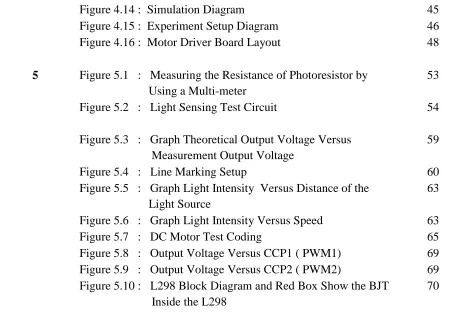
2.2 Literature 2
Title : Light Rover
Author : Thientu Ho and David Shu April 22, 2005 [2]
Institute : Cornell University,Ithaca, New York, United Stated.
Light Rover is a robot that can sense and follow light. A user can shine a flashlight at
its front and Light Rover will respond by following the light source. Its speed is dependent
upon the intensity of the light detected. Light Rover uses a microcontroller for processing the
[image:20.612.175.452.349.561.2]sensor readings and responds by controlling the motors.
7
Light Rover is designed with two sensors in mind, a left and a right. When more light
is detected on the left side, the robot will move towards it by rotating the right motor forward
and the left motor backwards. The robot will know to move forward when both sensors
received about the same amount of light. The robot is only designed to respond to visible light.
The robot uses two (2) bipolar stepper motor as a wheel and based on it, a major
hardware design task in this project was to drive the bi-polar motors. These motors have no
center taps on their windings. Therefore, to reverse the direction of the magnetic field
produced by a coil, the current through the winding need to reverse by using the H-bridge
stepper motor control circuit.
The controller uses is Atmel MEGA32 microcontroller. The sensors uses for the light
rover are 2 CDS-T08 photocell sensors. The light sensing circuit consists of two photocells
mounted on either side of the vehicle. The photocell produces a variable resistance based on
light intensity.
8
2.3 Literature 3
Title : Veroboard Bot
Author : Jd Stufu, March 30, 2005 [3]
Institute : University of Valladolid, Valladolid, Spain
Veroboard Bot is a light sensing robot that can move towards a bright light source. The
robot has the ability to avoid obstacles while seeking for the location in its environment that
has the greatest amount of light. The Veroboard Bot uses PIC16F84A microcontroller as a
controller.
Veroboard Bot is a differential drive photophile robot with tactile sensor. Photophile
means that the robot will seek for the location with the greatest amount of light. It does this
through the use of its two light dependent resistor (LDR) sensors. The LDR changes in
resistance with respect to the amount of light expose to it. Its resistance is near infinity in
absolute darkness and near zero when in bright light. The Veroboard Bots have two LDR
sensors located in front of its, one on the left and one on the right.
Differential drive means it uses two DC motors for steering. Both motors turn on at the
same speed but opposite rotation (right motor clock wise and left motor counter clock wise) to
move the robot forward. To turn left, left motor if turned off while right motor turns on in
clockwise rotation. To turn right the left motor is turned on in counter clockwise rotation while
the right motor is turned off. To move backwards, the motors should both turn on at the same
speed but opposite their direction of rotation is in opposite to the rotation of direction while
moving forward. The direction of rotation of the DC motor shaft is dependent on the polarity
of supply voltage applied to its terminal. Changing the polarity of the supply voltage changes
the direction of rotation of the DC motor shaft. Changing the polarity of the supply voltage
can be done by a solid state switch in H-bridge configuration. These solid state switches are
already integrated inside a chip called L293. The L293 has 4 inputs that directly controls the 2
9
10
2.4 Literature 4
Title : Light Seeking Robot
Author : Nicholas David Densley May 6, 2001 [4]
Institute : Sheffield Hallam University , South Yorkshire , England
This project is aimed at looking into the coding required for a light seeking robot. The
rational for this is to look into what AI programming techniques can be used to enable a robot
to cope with a dynamic environment. A dynamic environment is an area that is not clear of
obstacles and the robot must be able to navigate them in an appropriate manner whilst taking
into account its own power considerations.
This project aims to produce a small light seeking robot to demonstrate some of the
coding produced. To control the robot an embedded PIC16F877 chip is to be used. The base of
the robot is simply two bi-directional dc motors in a plastic casing. An L293N driver chip has
been selected, this chip is capable of supplying a constant 1A per channel, to two

![Figure 2.2 : Light Rover [2]](https://thumb-us.123doks.com/thumbv2/123dok_us/139125.16269/20.612.175.452.349.561/figure-light-rover.webp)
![Figure 2.3 : Differential Steering [3]](https://thumb-us.123doks.com/thumbv2/123dok_us/139125.16269/23.612.112.517.85.404/figure-differential-steering.webp)
