UNIVERSITI TEKNIKAL MALAYSIA MELAKA
AUTOMATIC BOX PACKING DEVICE
This report submitted in accordance with requirement of the Universiti Teknikal Malaysia Melaka (UTeM) for the Bachelor Degree of Manufacturing Engineering
(Robotic and Automation) with Honours.
by
MOHD SYAHIRAN BIN MOHAMED
DECLARATION
I hereby declare that this report entitled “Automatic Box Packing Device” is the result of my own research except as cited in the references.
Signature :
Author’s Name : Mohd Syahiran bin Mohamed
APPROVAL
This report is submitted to the Faculty of Manufacturing Engineering of UTeM as a partial fulfillment of the requirements for the degree of Bachelor of Manufacturing Engineering (Robotic and Automation). The members of the supervisory committee are as follow:
(Main Supervisor)
i
ABSTRACT
ii
ABSTRAK
iii
DEDICATION
Specially dedicated to
iv
ACKNOWLEDGEMENTS
v
TABLE OF CONTENT
Abstract i
Abstrak ii
Dedication iii
Acknowledgement iv
Table of Content v
List of Tables viii
List of Figures xi
List Abbreviations x
1.0 INTRODUCTION 1
1.1 Background 1
1.2 Problem Statement 2
1.3 Objective 2
1.4 Scope 2
2.0 LITERATURE REVIEW 3
2.1 Introduction 3
2.2 Introduction of Packaging 5
2.2.1 Package development considerations 6
2.2.2 Packaging machines 6
2.3 Previous work 8
2.3.1 Automatic packaging machine for boxes with paper end liner 8 2.3.2 Pressure roller device for laterally retaining boxes in packaging 9
Machine with automatic box feed
2.3.3 Automatic packaging machine for closing over filled boxes 10 2.3.4 Supertaper 4AR Fully Random Automatic Case Taper 11
2.3.5 Automatic Case Taper 12
vi
2.4. 1 Motor 13
2.4.2 Microcontroller 15
2.4.3 Sensor 16
3.0 METHODOLOGY 19
3. 1 Introduction 19
3.2 Planning 19
3.3 Discussion 22
3.4 Research about Project 23
3.5 Designing/sketching 23
3.5.1 Preliminary System Design 24
3.6 Drawing 25
3.7 Material Selection 25
3.8 Fabricate 28
3.8.1 Interfacing/repair 28
3.10 Testing and writing report 29
4.0 RESEARCH AND DEVELOPMENT 30
4.1 Mechanical part 30
4.1.1 Device platform or base development 30
4.1.2 Slider design 33
4.1.3 Slider holder 34
4.1.4 Gripper holder 35
4.1.5 Grippers design 36
4.1.6 Motor holder 37
4.2 Electrical part 40
vii
5.0 RESULT AND DISCUSSION 50
5.1 Result 50
5.1.1 Slider Analysis 50
5.1.2 Motor speed analysis 51
5.1.3 Gripper Analysis 52
5.1.4 Checking the Connection of Circuit 54
5.1.4 Result of Project 55
5.2 Discussion 56
5.2.1 Mechanical Part 56
5.2.2 Electrical Part 57
5.2.3 Programming Part 57
6.0 CONCLUSION 58
6.1 Conclusion 58
6.2 Suggestion for Further Works 59
REFERRENCES 60
APPENDICES 63
A Solidwork Drawing 63
B Steps of the Process 66
C Programming Code 67
viii
LIST OF TABLES
Table 3.1 Gantt chart of work planning for PSM 1 and PSM 2 20
Table 4.1: Phase of the Process 45
Table 4.2: Function Each Of Pin Microcontroller. 46
ix
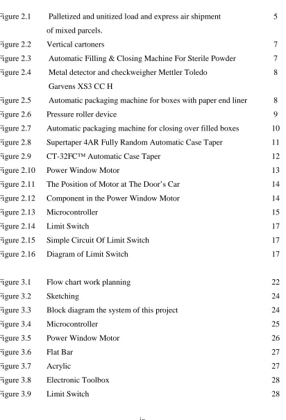
LIST OF FIGURES
Figure 2.1 Palletized and unitized load and express air shipment 5 of mixed parcels.
Figure 2.2 Vertical cartoners 7
Figure 2.3 Automatic Filling & Closing Machine For Sterile Powder 7 Figure 2.4 Metal detector and checkweigher Mettler Toledo 8
Garvens XS3 CC H
Figure 2.5 Automatic packaging machine for boxes with paper end liner 8
Figure 2.6 Pressure roller device 9
Figure 2.7 Automatic packaging machine for closing over filled boxes 10 Figure 2.8 Supertaper 4AR Fully Random Automatic Case Taper 11
Figure 2.9 CT-32FC™ Automatic Case Taper 12
Figure 2.10 Power Window Motor 13
Figure 2.11 The Position of Motor at The Door’s Car 14
Figure 2.12 Component in the Power Window Motor 14
Figure 2.13 Microcontroller 15
Figure 2.14 Limit Switch 17
Figure 2.15 Simple Circuit Of Limit Switch 17
Figure 2.16 Diagram of Limit Switch 17
Figure 3.1 Flow chart work planning 22
Figure 3.2 Sketching 24
Figure 3.3 Block diagram the system of this project 24
Figure 3.4 Microcontroller 25
Figure 3.5 Power Window Motor 26
[image:13.595.113.525.146.751.2]Figure 3.6 Flat Bar 27
Figure 3.7 Acrylic 27
Figure 3.8 Electronic Toolbox 28
x
Figure 4.1: Marking the Material 31
Figure 4.1: Marking the Material 31
Figure 4.3: Drill the Material 31
Figure 4.4: Hole to Join the Component 31
Figure 4.5: Tight the Screw of Join 32
Figure 4.6: Leg of the Device 32
Figure 4.7: Join At the Top of Leg 32
Figure 4.8: Base of the Device 32
Figure 4.9: Slider (Front) 33
Figure 4.10: Slider (Back) 33
Figure 4.11: Punch the Slider 33
Figure 4.12: Drill the Slider 33
Figure 4.13: Marking the Flat Bar 34
Figure 4.14: Cut the Flat Bar 34
Figure 4.15: File the Flat Bar 34
Figure 4.16: Drill the Flat Bar 34
Figure 4.17: Punch the Small Flat Bar 34
Figure 4.18: Position of the Holder 34
Figure 4.19: Marking the Flat Bar 35
Figure 4.20: Cut the Material 35
Figure 4.21: Drill the Material 35
Figure 4.22: Join the Holder by Using Hinge 35
Figure 4.23: Cut the Acrylic 36
Figure 4.24: File the Acrylic 36
Figure 4.25: Punch the Acrylic 36
Figure 4.26: Drill the Acrylic 36
Figure 4.27: Gripper 37
Figure 4.28: Marking the Material 37
Figure 4.29: Cut the Material 37
xi
Figure 4.31: Position of the Holder 38
Figure 4.32: Holder for Second Motor 38
Figure 4.33: Material of The Motor Holder 38
Figure 4.34: Cut the Material 38
Figure 4.35: Holder for Third Motor 38
Figure 4.36: Flow Chart for Mechanical Structure 39 Figure 4.37: Electrical Circuit for Automatic Box Packaging Device. 40
Figure 4.38: Project Board 40
Figure 4.39: Position of Relay 41
Figure 4.40: Position of Diode 41
Figure 4.41: Transistor 41
Figure 4.42: Voltage Regulator 42
Figure 4.43: Electrolyte Capacitor 42
Figure 4.44: Graph of Difference Type of Capacitor 43
Figure 4.45: Voltage Regulator 43
Figure 4.46: Crystal 20mhz 44
Figure 4.47: Circuit Of Automatic Box Packaging Device. 44
Figure 4.48: Multimeter 44
Figure 4.49: Flow Chart of Current Flow to the Microcontroller and Motor. 45
Figure 4.50: Flow Chart of Step of the Process 46
Figure 4.51: Select the Name of Device 47
Figure 4.52: Set the Value of Clock 47
Figure 4.53: Content of Information about Project 48
Figure 4.54: Save and Default the Program 48
Figure 4.55: Write the Coding 49
Figure 4.56: Build the System 49
Figure 4.57: The Result of the System 49
Figure 5.1: Power Window Motor 51
Figure 5.2: First Motor 52
xii
Figure 5.4: Third Motor 52
Figure 5.5: The Join of the Gripper 53
Figure 5.6: The Angle of the Gripper (Open Position) 53
Figure 5.7: Home Position of All Components 53
Figure 5.8: Measure the Distance between Two Grippers 53
Figure 5.9: Testing the Current Flow 54
Figure 5.10: Sensor (Limit Switch) 54
Figure 5.11: Box 55
Figure 5.12: Gripper Open 55
Figure 5.13: Gripper Y-Axis Close (Beginning) 55
Figure 5.14: Gripper Y-Axis Close (Ending) 55
Figure 5.15: Gripper X-Axis Close (Beginning) 56
xiii
LIST OF ABBREVIATIONS
PLC - Programmable Logic Controller
PC - Personal Computer
1
CHAPTER 1
INTRODUCTION
1.1 Background
In industrial nowadays, packaging is a stage that is important because to make a product safe and good in condition when delivering to customer as well as to both sellers and buyers of the products. Most commercial packaging serves two basic functions which are protecting the product from damage during shipping, and promoting the product to the ultimate consumer. Operators must pack the boxes carefully so the products still in good condition but it will take a time if the operators have a lot of boxes to package. Therefore, this project an automatic box packaging device will make the process become fast that replaces the operator for packaging the boxes. An automatic box packaging device will be adaptable to production-line speeds, increase the product's density, and satisfy legal requirements.
However, this machine not only for industrial or factory but it also can be used for anybody that wants to package their boxes. This project will used microcontroller and sensors to make it run systematically. This project also will use motor to move gear that is to control arms to close the boxes. This arm will move step by step by following the program in the microcontroller until the box was packaged.
2
1.2 Problem Statement
In industrial nowadays especially in Malaysia, many factories has used the packaging machine to package their product. However, there are only few factories using a box packaging machine. It is because they think it not important for their factory. Packaging machine nowadays is expensive because the component and the material that they use is of a high quality. Therefore, the prices make a factor to them to buy the machine. The sizes of the machine also take a lot space in the factory. So, they must arrange the component and equipment in the factory before buying the machine. Few factories are using operator or human to package the boxes. However, the problems that occur from operators is they will take a time to package a lot of boxes. So, the customer must waiting and order a few quantity of product it they want the product early.
1.3 Objectives
The objectives of this project are:
a) To design and develop an automatic device that is easy to package various sizes of boxes.
1.4 Scope
In order for the project to complete successfully, the scope needed to ensure the completions of the project are as follow;
a) Design mechanism of each part of this project.
b) Construct a prototype of automatic box packaging device. c) Program microcontroller by using microcontroller software. d) Interface between sensor, and controller.
3
CHAPTER 2
LITERATURE REVIEW
2.1 Introduction
This chapter presents the literature review relevant to the project. This literature review is a critical look at the existing research that is significant to the works that are carrying out. This chapter is containing the summary the relevant research, vital that to evaluate this project, show the relationship between different works and show how it relates to the project. This chapter also contains historical issues, theoretical issues and methodological issues.
2.2 Introduction of Packaging
4
It is sometimes make easy to categorize packages into three functions which are primary, secondary and tertiary.
a) Primary packaging is the material that first envelops the product and holds it. This usually is the smallest unit of distribution or use and is the package which is in direct contact with the contents.
b) Secondary packaging is outside the primary packaging – perhaps used to group primary packages together.
c) Tertiary packaging is used for bulk handling, warehouse storage and transport shipping. The most common form is a palletized unit load that packs tightly into containers.
Depending on the use, primary packing such as shrink wrap used when applied directed to the product, secondary packaging when combining smaller packages, and tertiary packaging on some distribution packs.
According to the article from Kenneth (2000), he state that from the very earliest times, humans consumed food where it was found. To make sure the product in good condition, families and villages need for packaging of goods, either for storage or transportation. When containers were needed, nature provided gourds, shells, and leaves. Later, containers were fashioned from natural materials, such as hollowed logs, woven grasses and animal organs.
For each product's needs, there are good packaging solutions. Though packages are often take easy, they are the result of many years of innovation in some cases accidental. A brief review of the more popular packaging developments is included in this fact sheet. There are some types of material packaging which is paper, glass, metals and plastics.
5
our purchases. An example of semi-flexible packaging is the paperboard boxes that cereal, many other food products, small household items, and many toys are packaged in. For many non-food items, the packaging is made more rigid by formed packing materials that slip inside the box and hold the product and its accessories or components in place. Forms of rigid packaging include crates, glass bottles, and metal cans.
In 20th century, paper and paperboard packaging increased in popularity. Then with appear of plastics as a significant player in packaging, paper and its related products were replaced in many uses. Lately that trend has slowed as designers have tried to respond to the perception that plastic is environmentally unfriendly. The fact is that decreasing that amount of material in packaging is usually more important than the composition of the package to get the most environmentally friendly form of packaging.
2.2.1 Package Development Considerations
An integral part of the new product development process is often by package design and development. Moreover, development of a package can be a separate process, but must be linked closely with the product to be packaged. Package design starts with the identification of all the requirements like structural design, marketing, shelf life, quality assurance, logistics, legal, regulatory, graphic design, end-use, and environmental. The design criteria, time targets, resources, and cost constraints need to be established and agreed upon.
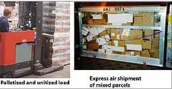
Figure 2.1: Palletized and unitized load and express air shipment of mixed parcels.
[image:22.595.175.464.546.696.2]6
Logistics system of transport packaging needs to be matched to transport packaging. Packages designed for controlled shipments of uniform pallet loads may not be suited to mixed shipments with express carriers. An example of how package design is affected by other factors is the relationship to logistics. When the distribution system includes individual shipments by a small parcel carrier, handling, and mixed stacking make severe demands on the strength and protective ability of the transport package. If the logistics system consists of uniform palletized unit loads, the structural design of the package can be designed to those specific needs like vertical stacking, perhaps for a longer time frame. A package designed for one mode of shipment may not be suited for another.
2.2.2 Packaging Machines
A choice of packaging machinery includes technical capabilities, labor requirements, worker safety, maintainability, serviceability, and reliability, ability to integrate into the packaging line, capital cost, floor space, flexibility, energy usage, and quality of outgoing packages, qualifications, throughput, efficiency, productivity, and ergonomics. (http://www.newworldencyclopedia.org)
There is much type of packaging machines. Some of the types are following below: a) Blister, Skin, and Vacuum Packaging Machines
b) Capping, Over-Capping, Lidding, Closing, Seaming, and Sealing Machines c) Case and Tray Forming, Packing, Unpacking, Closing, and Sealing Machines d) Cleaning, Sterilizing, Cooling, and Drying Machines
e) Feeding, Orienting, Placing (and related) Machines f) Filling Machines: Handling liquid and powdered products g) Package Filling and Closing Machines
7
Figure 2.2: Vertical cartoners (http://www.ima.it/Vertima_2l10c86f295m.asp)
This machine is suitable for high quality cream jars, lotions and perfumes’ in bottle. It also can be used for feeding system for liner, sachets, spatulas, protection ring, tool-free fast changeover, PLC Siemens and steel-it finishing.
Figure 2.3: Automatic Filling & Closing Machine for Sterile Powder (http://www.tradeindia.com)
[image:24.595.215.423.411.581.2]