Two phase discharge flow prediction in safety valves
William Dempster
a,
Wael Elmayyah
ba
Department of Mechanical and Aerospace Engineering, University of Strathclyde, Glasgow, G1 1XJ, UK
b
Military Technical College, Egyptian Armed Forces, Cairo, Egypt ,
Abstract
Safety Relief Valves (SRV) are necessary elements in the protection of any pressurised system and the prediction of the expected discharge flows is an important consideration for the valve sizing to ensure that rupture pressures do not occur. The high speed flows that occur inside the SRV are complex particularly when a two-phase flow is involved and lead to a less capable protection device which result in larger valves compared to single phase flows. In this paper the ability of a CFD based two phase mixture model to predict the critical flows of air and water through a safety valve is examined. An industrial refrigeration safety relief valve of ¼” inlet bore size has been tested experimentally over a pressure range of 6-15 barg and air mass qualities from 0.1-1 when discharging to near atmospheric conditions for a fully open condition. A two-dimensional mixture model consisting of mixture mass, momentum, and energy equations, combined with a liquid mass equation and the standard k- ε turbulence model for mixture turbulent transport has been used to predict the two phase flows through the valve. The mixture model results have been compared with the Homogenous Equilibrium Model (HEM) commonly used for in valve sizing in non flashing two phase flow conditions. The accuracy of the models over the two phase flow range are quantified and discussed
Keywords: Safety relief valves: two phase discharge, prediction, CFD
1.Introduction
Unfortunately, in relief valves the two phase flow imposes more limiting conditions since critical flow occurs much more easily and imposes more limiting discharge flowrates. Since the proper operation of safety relief valves relies on knowledge of the possible exit flowrates how a two phase flow affects the valve performance is of significant interest. The existing predictive models for two phase discharge flows use mathematically simple semi-empirical algebraic approaches with uncertain accuracy and generality to size and design relief valves. Computational Fluid Dynamics techniques are available but have been less well validated. This paper addresses these gaps in the technical literature by presenting a series of predictions using a two phase mixture model and comparing them against experimentally measured two phase discharge flows. A relatively simple two phase flow using air and water is examined. This condition includes the effects of phase distribution, velocity slip effects and interphase phase heat transfer but excludes the more complex effects of mass transfer due to liquid flashing commonly found in single fluid systems. Also, the valve conditions studied are those when the valve is fully open. While fractional opening conditions can be important the emphasis here is a comparison with existing calculation approaches which are restricted to fully open valve conditions. The model and validation methodology are discussed and the predictions compared directly with the experimental data and model accuracies quantified.
2.Background
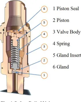
[image:2.539.210.351.364.541.2]The valve investigated in this study was a conventional spring loaded safety relief valve used primarily in the industrial refrigeration industry. Figure 1 shows a cross section of the assembled valve and has a ¼” inlet diameter to provide dimensional reference. The valve consists of a moveable piston that is loaded by a spring to the required relief. The piston has a sealing face which with sufficient spring load will contain the pressure of the system by ensuring a seal with the valve seat machined into the valve body.
Fig. 1 Safety Relief Valve
The operation of the valve is a dynamic process, however the flow processes of the valve can be examined by assuming quasi static conditions where pressure wave effects are assumed negligible and the valve flow conditions are similar to those experienced at steady state conditions. This is more applicable to the steady operation or closing phases than the opening phase of a safety relief valve operation.
In this study the objectives were to investigate the ability of a CFD based mixture model for the multi-phase air water flow to predict the critical flow conditions in the safety valve. The two phase flow conditions are generally high speed flows and dominated by the annular or dispersed flow regimes. The mixture model is a simplified model of the full multiphase model and is considered a good alternative when simulating a dilute flow of droplets of liquid in a gas. In this work the commercial code Fluent 6.3.2 has been used as a vehicle to examine this model. Specifically the CFD model assumes that mechanical and thermal equilibrium exists between the phases at a local level and is used to assess for the effect of phase distributions on the predictions. The model is compared to the Homogenous Equilibrium Model (HEM), an algebraic based model commonly used for critical flow predictions and to experimental test data using air and water so that the model differences can be assessed and quantified.
3.Computational Model
The two phase flows which occur in the valve are dominated by the accelerating gas flows as the gas expands through the valve. This creates a high speed highly dispersed droplet or droplet/film flow in the small flow area paths of the valve. Sonic and supersonic speeds are easily reached and while no phase change is expected in the conditions examined in this study thermal non equilibrium effects may arise due to the low temperatures of the expanding gas and the higher liquid thermal inertia. For dispersed two phase flows, the mixture model is regarded to be appropriate for droplets of liquid in gas. In the mixture model used here the effects of velocity differences (slip) between the phases are ignored and assumed to be important only in the initial phase mixing region at the liquid injection nozzle. The thermal non-equilibrium is also neglected and may result in a divergence from reality as the liquid flowrate is increased due the higher liquid inertia. The mixture model equations are fully described by Manninen (1996) [5] and in the Fluent Technical Manuals (2006) [6]. For comparison purposes, the HEM equations presented by Darby (2004) [7] have been used here.
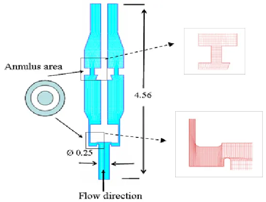
and second order central difference for the diffusion terms. For the volume fraction equation the discertization scheme was first order upwind for the convection terms and second order central difference for the diffusion terms. All cases have converged in about 60 min on a 2.4 GHz desktop PC.
Fig. 2 Computational mesh
4.Experimental set up and procedures
An experimental flow facility, for valve testing under steady state flow conditions was developed to allow independent control of the valve piston position and upstream water injection at various operating upstream air pressure conditions, Figure 3.
Figure 3 Schematic of valve two phase test facility
The rationale was to measure the air flowrates at constant upstream pressure for variations in injected water
Piston connecting rod Liquid and air to separator/storage tank
Air Flow
P
Liquid injection nozzle
Test Valve Piston Piston traverse unit
[image:4.539.92.446.427.576.2]flowrate. Thus, for each test condition, determined by setting the piston lift, upstream pressure and liquid flowrate, the air mass flow becomes the uncontrolled quantity determined by the circumstances of the two phase interaction with the valve. The water is injected into the flowing air upstream of the valve using a spray nozzle allowing the liquid to mix prior to entering the valve. Downstream of the valve, a separator is used to separate the water and the air. The water collected in the separator also acts as a water supply for the water injection pump. The test rig, Figure 3, consists of a 100 mm (4 inch) diameter pipe connected to a compressed air system to deliver high pressure (1-15 bar) compressed air to the valve. The tested safety valve is connected to the pipe via a brass converging section to adapt to the valve entrance. A liquid injection nozzle is fitted into the converging section to inject the water. The injection nozzle located in the centre of the pipe produces a uniform full cone spray with a low spray angle of 30o. A PVC T junction with a 50 mm diameter side exit is connected to the valve to direct the two phase mixture to a separator. The T junction was designed such that it has a minimum resistance to the exit flow and could be maintained close to atmospheric pressure. It has a pressure tapping fitted to measure the pressure at the valve outlet. The valve piston is attached to a 250 mm long 6 mm diameter rod which passes through the far end of the PVC tube end and is connected to a lead screw and traverse table allowing the piston position to be adjusted. The piston movement is in the range of 0-5 mm and was measured by a Mitutoyo digital dial indicator with sensitivity of 0.001 mm. To allow the connecting rod to be inserted the original valve required to be modified by removing the spring and associated gland/spring inserts resulting in a modified gland being used. While these changes detracted from the correct representation of the relief valve, their effect on the mass flows have been found to have a minimal effect since the flows are choked upstream of these components. The water injection system consists of a positive displacement diaphragm water pump (Hydra Cell D/G-04 series) connected to the injection spray nozzle via a high pressure hose. The pump has a maximum flowrate of 11 l/min and will deliver the flow independently of the downstream pressure up to 100 bar. The pump is driven by an AC motor controlled by a speed controller, which allows adjustment of the water flow rate. Upstream of the injection nozzle, a turbine flow meter (Omega Engineering FTB 1411) is fitted to facilitate measurement of the water flow rate; it has a flow rate range of 0.4 - 10 l/min and has an accuracy of +/- 1% of the reading. A pressure relief valve is attached to the pump outlet to protect the circuit from any unexpected high pressure. A bladder accumulator (FlowGuard DS-20) is also connected to the pump outlet to damp the pulsating water flow rate from the pump. The air flowrate was measured using a Sierra Vortex mass flowmeter (Innova mass 240) and accurate to <1% of reading. The upstream pressure, and outlet pressure are measured by Bourdon pressure gauges. The range of upstream pressures (1-15 bar) and water flow rates (1-10 L/min) give a working air flow rate from 0.015 to 0.86 kg/s and a water mass fraction range from 0 to 0.9.
Test data presented in this paper was taken at a pressure of 170 psi for a liquid flowrate of 0-10 L/min and at a fixed piston lift position of 5 mm, which corresponds to a fully open position of the valve. This allowed a 0-0.9 range of liquid mass fractions to be examined and influences the degree of mechanical and thermal non-equilibrium, ie velocity differences and the temperature changes during the expansion process. The temperature of the gas decreases during the expansion process as the fluid accelerates but will be restricted by the heat transfer from the liquid which changes less due its larger thermal inertia. This effect will increases as the liquid mass flow increases.
5. Results and Discussion
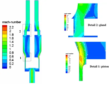
The flowrate through the valve is controlled by the sonic flow locations in the valve. For the fully open valve, sonic flow occurs at the piston side wall location at the rear of the piston and at the gland location shown in Figure 4 ; see detail 1 and 2 respectively.
Fig. 4 CFD results for a liquid flow x L/min and upstream pressure of 170 psi
The figure shows the mach number for the two phase flow, as defined below,
Where um is the mixture velocity, and am is the sonic speed in the mixture which is taken to be for a
homogeneous flow assuming air volume fractions higher than 0.9 as follows
Where, α is the void fraction and is the mixture density determined from
ρa and ρl are the densities of the gas and liquid respectively.
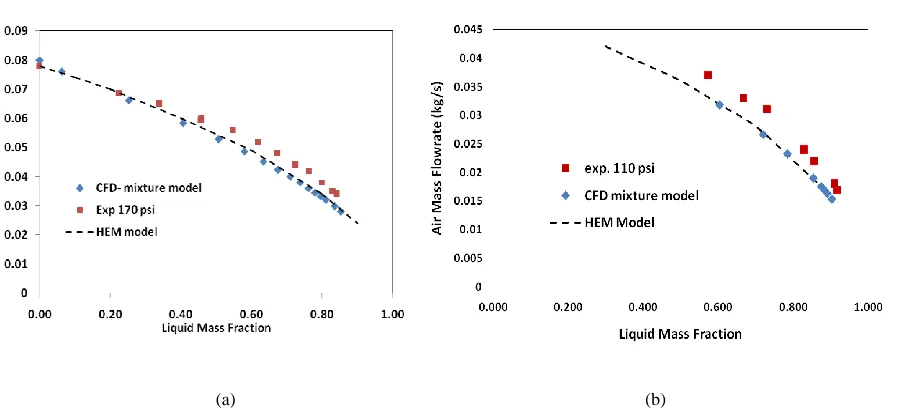
Figure 4 shows that the first sonic location occurs at the piston. It is this position and area that determines the critical flowrates for all conditions that the valve operates at. It is also noticeable that the flow is predicted to accelerate further to supersonic conditions downstream of the piston with the potential to create oblique shock systems in these locations. While this has no influence on the mass flow it does affect the pressure in these regions which will influence the forces on the piston, potentially affecting the opening and closing conditions. The gas massflow predictions of the models against the experimental data for the algebraic based HEM model and the CFD based mixture model are shown in Figure 5.
[image:7.539.44.493.184.388.2]
(a) (b)
Fig. 5 Air mass flow predictions for CFD and HEM models against experimental data
Fig. 6 CFD – Experimental Error
(The data has been fitted to allow the difference to be calculated at corresponding liquid mass fractions)
6.Conclusions
Calculations to predict the critical two phase mass flowrates through a safety relief valve have been carried out using a simple HEM algebraic methods and a mixture based CFD model and compared against experimental test data using air-water conditions. The results indicate that
(i) The HEM method and CFD mixture model predict similar results across the mass fraction range
studied.
(ii) Both the HEM and the CFD methods satisfactorily predict the critical two phase gas flowrate for
liquid mass fractions up to 0.4. For larger liquid mass fractions up to 0.9 errors of 15% have been observed.
7.References
[1] Reindl D.T. , Jekel T.B. Pressure Relief Capacity Determination, ASHRE Transactions Volume 114, part 1, 2009
[2] ISO 4126-10 Safety devices for protection against excessive pressures-sizing of safety valves and connected inlet and outlet lines for gas/liquid two phase flow 2010.
[3] Dempster W., Elmayyah. W., A computational fluid dynamics evaluation of a pneumatic safety relief valve. The 13th International conference on Applied Mechanics and Mechanical Engineering (AMME), May 2008.
[4] Dempster W.M., Lee C. K., and Deans J., Prediction of the flow and force characteristics of safety relief valves, Proceedings of PVP2006-ICPVT-11 2006 ASME Pressure Vessels and Piping Division Conference, July 2006.
[5] Manninen M, Taivassalo V, and Kallio S. On the mixture model for multiphase flow. Technical report, Technical Research Center of Finland, 1996.
[6] Fluent 6.3 User Guide, 2006