A wide bandwidth free-electron laser with mode locking using current modulation
This article has been downloaded from IOPscience. Please scroll down to see the full text article.
2011 New J. Phys. 13 063012
(http://iopscience.iop.org/1367-2630/13/6/063012)
Download details:
IP Address: 130.159.24.185
The article was downloaded on 10/06/2011 at 10:22
Please note that terms and conditions apply.
T h e o p e n – a c c e s s j o u r n a l f o r p h y s i c s
New Journal of Physics
A wide bandwidth free-electron laser with mode
locking using current modulation
E Kur1, D J Dunning2,3, B W J McNeil2, J Wurtele1,4 and A A Zholents5,6
1University of California, Berkeley, CA 94720, USA 2University of Strathclyde (SUPA), Glasgow G4 0NG, UK
3ASTeC & Cockcroft Institute, STFC Daresbury Laboratory, Warrington,
WA4 4AD, UK
4Lawrence Berkeley National Laboratory, Berkeley, CA 94720, USA 5Argonne National Laboratory, Argonne, IL 60561, USA
E-mail:[email protected]
New Journal of Physics13(2011) 063012 (18pp)
Received 21 January 2011 Published 8 June 2011 Online athttp://www.njp.org/
doi:10.1088/1367-2630/13/6/063012
Abstract. A new scheme for mode locking a free-electron laser (FEL) amplifier is proposed based on electron beam current modulation. It is found that certain properties of the original concept (Thompson and McNeil 2008
Phys. Rev. Lett. 100203901), based on the energy modulation of electrons, are improved, including the spectral brightness of the source and the purity of the series of short pulses. Numerical comparisons are made between the new and old schemes and between a mode-locked FEL and a self-amplified spontaneous emission FEL. Illustrative examples using a hypothetical mode-locked FEL amplifier are provided. The ability to generate intense coherent radiation with a large bandwidth is demonstrated.
6Author to whom any correspondence should be addressed.
Contents
1. Introduction 2
2. Mode locking in an atomic laser oscillator 3
3. Mode generation in a periodic undulator/chicane lattice 5
4. Mode coupling and locking in a free-electron laser (FEL) amplifier 6
5. Simulation results 10
5.1. Mode locking using energy modulation . . . 10
5.2. Mode locking using peak current modulation . . . 14
5.3. Broad bandwidth FEL. . . 15
6. Conclusion 17
Acknowledgments 18
References 18
1. Introduction
As proposed in [1], the concept of mode locking [2] from a conventional atomic laser can be applied to a free-electron laser (FEL) amplifier. Placing magnetic chicanes between undulator sections and forming a periodic array of undulator/chicane modules, as shown in figure 1, imposes an axial-mode structure on the signal generated by the FEL, similar to the longitudinal modes of a conventional laser cavity. At resonance in an FEL, a radiation wave front propagates (slips) Nu resonant wavelengths through an electron bunch in one undulator section of Nu
periods. The magnetic chicanes introduce an extra slippage of the radiation with respect to the electron bunch. Only those radiation wavelengths that have an integer number fit into the relative radiation/electron bunch slippage in one module will remain phase-matched to constructively interfere over many such modules. Such wavelengths that constructively interfere form the modes of the radiation field to create a comb of equally spaced modes in the output frequency spectrum. As suggested in [1], neighboring modes can be made to lock in phase by modulating the electron beam energy at the mode spacing. As with the atomic laser, this mode locking modifies the temporal envelope of the output field from a continuous wave to a series of short, periodically spaced pulses.
In this paper it is shown that mode locking can be achieved by replacing the beam energy modulation with a beam current modulation of the same period. This change helps to produce a cleaner series of short pulses and to increase the spectral brightness of the source. It is also shown that mode locking can be used to control the bandwidth of the radiation field by varying the length of each undulator section, while maintaining the same overall slippage in each undulator/chicane section. Particularly appealing is the demonstrated ability to achieve a large bandwidth, allowing probing the properties of matter in both the spectral and temporal domains. Wide bandwidths may also be of interest in experiments currently performed using high-order laser harmonics, e.g. in measurements of the transmission and reflectivity spectra of various materials, similar to studies described in [3].
Figure 1. A schematic of an FEL design with mode-locking capabilities, as shown in [1]. Chicane magnets are placed between each undulator module to generate the desired slippage between the radiation and the electron beam to create the radiation modes. The schematic includes a short beam-energy modulation undulator at the start of the FEL, which allows coupling between the modes.
in [2] is first considered. The fields passing through any given cross-section are reflected at the ends of the cavity and there is a round-trip time T =P/c, wherePis the perimeter of the laser cavity andcis the speed of light, after which the field pattern repeats itself. Consider the electric field of the signal in the cavity defined as a function of time with Fourier transform ofε(ω)˜ . As this signal circulates, the axial modes of the cavity become more pronounced in the spectrum, as illustrated in figure2. AfterNround trips, there areN copies of this signal, each delayed by a multiple of the round-trip time:
ε(N)(t) =
N−1
X
n−0
ε(t−nT). (1)
Applying a Fourier transform, using the Fourier time shifting identity F{X(t−a)} =
e−iωaF
{X(t)} and the summation identity PNn=−01einωa
=(1−eiNωa)/(1
−eiωa), an expression for the intensity I(N)(ω)
∼ |˜ε(N)(ω)
|2is obtained:
I(N)(ω)= 1−cos(ωN T)
1−cos(ωT) I
(0)(ω), (2)
where I(0)(ω)is the initial spectral intensity.
2. Mode locking in an atomic laser oscillator
Thus, the spectrum develops a ‘comb structure,’ meaning it becomes peaked at the axial mode frequencies. In this way, a signal inside a laser cavity excites the various axial modes. An interesting result occurs when the axial modes are all in phase: the time-domain signal takes on a pulsed pattern, closely resembling the comb structure of the frequency domain. Defining the time whenN adjacent axial modes are all in phase to bet =0, the (complex) electric fields may then be written as ε˜(n)(t)
=ε0e−iωnt, where ωn=ω0+ωant and ωa=2π/T is the axial
mode spacing. When all of the modes have equal amplitude, the total electric field is then given by [2]:
˜
ε(N)(t) =ε0
N−1
X
n=0
e−iωnt =ε
0e−iω0t
1−e−iωaN t
Figure 2. Theoretical time-domain (left) and frequency-domain (right) plots of the electric field amplitude at the output of a conventional laser cavity oscillator with round trip timeT =1.51 (in arbitrary units), as in [2]. The plots are shown after one trip (top), two trips (middle) and three trips (bottom).
and the intensity by:
I(N)(t)= 1−cos(ωaN t)
1−cos(ωat)
I(0)(t). (4)
The time-domain waveform is then composed of a periodic series of short pulses. This is true only when the modes are all phase locked. However, a periodic pulse structure of sufficiently short pulses can be obtained if each mode phase locks only with its nearest neighbors. In a conventional atomic laser oscillator, a modulation of the cavity parameters at a multiple of the axial mode spacingωacan cause neighboring modes to couple and phase lock. A sharply peaked
3. Mode generation in a periodic undulator/chicane lattice
Following [1], a review is presented of how a similar modal structure may be produced in the FEL amplifier by introducing magnetic chicanes between undulator sections. The evolution of the radiation field in an undulator in the absence of the high-gain FEL interaction may be approximated by the following wave equation [1]:
∂A(¯z,¯z1)
∂z¯ +
∂A(z¯,z¯1)
∂z¯1 =b0(z¯1), (5)
where the scaled units introduced in [4] are used, i.e. A is the scaled electric field, z¯=z/lg
is the interaction length along the undulator in units of the one-dimensional gain length lg,
¯
z1≈(z− ¯vzt)/lcis the local electron bunch coordinate in units of the cooperation length (which
is also the approximate coherence length), andb0(z¯1)is a small initial electron bunching source term assumed constant with respect to z¯. In these units, if the electron bunch and radiation co-propagate a scaled length1¯zalong the undulator, a radiation wave front propagates through the electron bunch 1z¯1=1z¯ in the local electron bunch coordinate [4]. After applying the Fourier transform
F{X(¯z,¯z1)} ≡ ˜X(¯z,ω)¯ =
1
√
2π Z ∞
−∞
X(z¯,z¯1)e−iω¯z¯1dz¯1
in ¯z1 to equation (5), where ω¯ =(ω−ωr)/2ρωr is the frequency scaled with respect to the
resonant FEL frequency ωr andρ is the FEL’s Pierce parameter [5], the resultant transformed
equation can be solved with initial condition A˜(0,ω)¯ =0, to give the radiation field spectrum for a single undulator of scaled lengthl¯[1]:
˜
A(l¯,ω)¯ =ib˜0(ω)¯
¯
ω (1−eiω¯
¯
l)
eiω¯l¯= ˜b0(ω)¯ ¯lsinc(ω¯¯l/2)e−iω¯l¯/2. (6) A chicane and two drifts placed at the end of the first undulator will delay the electron beam and allow the radiation to propagate or ‘slip’ ahead of the electron beam by a length δ¯ in the local electron bunch coordinate z¯1. This additional slippage can be applied to the field (6) by using the Fourier time shifting identity of the previous section. Thus, assuming no electron/radiation interaction in the chicane, the field at the end of the first undulator/chicane module can be written as:
˜
A ¯l,ω¯=ib˜0(ω)¯
¯
ω (1−eiω¯
¯
l)
e−iω¯s¯, (7)
wheres¯= ¯l+δ¯ is the total slippage of a radiation wave front through the electron beam in the combined undulator/chicane module.
The total field emitted from N such identical undulator/chicane modules placed in series, as shown schematically in figure 1, is found by summingN such fields (7) each of which has had the slippage effects of subsequent undulator/chicane modules applied via the Fourier time-shifting identity. Hence:
˜
A(N)(ω)¯ =ib˜0(ω)¯
¯
ω (1−eiω¯
¯
l) e−iω¯s¯
N−1
X
n=0
e−iω¯ns¯, (8)
apart from a different complex phase term that arises from a different, but inconsequential, definition of a zero phase:
˜
A(N)(ω)¯ = ˜b0(ω)¯ ¯lsinc(ω¯ ¯l/2)
1−e−iNω¯¯s 1−e−iω¯¯s e
−iω(¯ ¯s−¯l/2).
(9)
Thus, we obtain for the intensity:
I(N)(ω)¯ ∼ | ˜A(N)(ω)¯ |2=(b˜0(ω)¯ ¯lsinc(ω¯l¯/2))2
1−cos(Nω¯s¯)
1−cos(ω¯s¯) . (10)
Equation (10) describes the intensity spectrum of a single undulator obtainable from equation (6), modulated by a comb structure (the ratio of functions in (10)) with scaled mode spacing of 1ω¯ =2π/s¯, similar in form to that for the conventional laser oscillator of equation (2).
4. Mode coupling and locking in a free-electron laser (FEL) amplifier
Although the basics of the FEL mode-locking theory match well with conventional laser theory, differences remain. In the conventional atomic laser oscillator, the gain of the radiation signal during one round-trip is relatively small and a buildup of the laser power occurs over a large number of round-trips. This is why mode locking is typically obtained when the laser is at, or near, saturation (the transient period of signal growth is not important). However, in the high-gain FEL amplifier considered here, the gain in each undulator/chicane module may be significantly larger than the round-trip gain of a conventional laser oscillator, and strong mode-coupling develops in the linear regime during exponential growth. The high-gain FEL interaction may be approximated by inserting an exponential amplitude gain factor eα into the wave form of the field equation (8) to obtain:
˜
A(N)(ω)¯ =ib˜0(ω)¯
¯
ω (1−e
iω¯`¯)e−iω¯¯s N−1
X
n=0
enαe−iω¯n¯s (11) and following the derivation of (10) to obtain the intensity:
I(N)(ω)¯ ∼(b˜0(ω)¯ l¯sinc(ω¯ ¯l/2))2eα(N−1)
cosh(αN)−cos(Nω¯s¯)
cosh(α)−cos(ω¯s¯) . (12)
In conventional lasers, the key to mode locking, and the generation of a well-defined temporal comb, is to introduce a fixed-period modulation (amplitude or phase) at a multiple of the frequency spacing of the axial modes [2]. In the FEL amplifier, an obvious parameter to vary is the beam energy, e.g. a sinusoidal modulation of the beam energy:γ =γ0+γmsin(ωmt),
where γ is the electron beam relativistic factor with subscripts ‘0’ and ‘m’ indicating the mean and modulation amplitude, respectively. The mode spacing of the FEL spectrum is given by 1ω¯ =2π/s¯, corresponding to 1ω=2πc/s in non-scaled units, analogous with the conventional laser mode-locked spectrum. In order to achieve mode locking, the modulation frequency must match the mode spacing i.e. ωm=1ω. Such modulation was shown to phase
lock neighboring modes to generate a well-defined temporal comb [1].
It was observed in the numerical simulations that the spectrum of the mode-locked FEL develops a second intermediate set of modes. These modes, not present in the theory or experiments of mode locking in a conventional laser, are seen to exist when mode locking is initiated using a sinusoidal energy modulation. Two peaks in the time domain output signal in the space of one modulation period are observed. This is because there are two favorable positions in the sinusoidal energy modulation where the electrons preferentially radiate, i.e. around the maxima and minima of the electron energy modulation where the energy gradients are smallest [6]. However, these extrema of the electron energy modulation also have different resonant wavelengths, which correspond to the central modes of the two sets of interleaved spectral modes. Furthermore, the sinusoidal energy modulation will also evolve due to chicane dispersion [6]. This causes the spacing of the extrema to change from half of the modulation period, with their positions converging within one modulation period as the chicanes longitudinally compress the modulated beam. By using a current modulation instead of an energy modulation, some of the additional spectral features associated with the energy modulated beam discussed above may be expected to be removed to give a ‘cleaner’ spectral and temporal output, and this is indeed found to be the case.
We now proceed with the development of a linear theory of mode locking in an FEL amplifier. In particular, we focus upon the introduction of a current modulation in the electron beam at the mode spacing generated by the undulator/chicane lattice.
The FEL equations averaged over the radiation field and undulator periods may be written [4,5]:
dθj(z¯)
dz¯ = pj(z¯)|¯z1
dpj(z¯)
dz¯ = −(A(¯z,¯z1)e
iθj(¯z)+c.c.)|
¯
z1
∂ ∂z¯ +
∂ ∂z¯1
A(z¯,z¯1)=χ(¯z1)he−iθ(z¯)i|z¯1,
(13)
where the local electron phase-space variables θj(z¯) and pj(z¯) are evaluated at z¯1 for j =
1, . . . ,N the number of macroparticles; he−iθ(¯z)i|z1 = 1
N PN
j=1e− iθj(z¯)|
z1 is an average over the
N localized electrons at the macroscopic position in the electron pulse¯z1; andχ(¯z1)=I(¯z1)/¯I
is the electron beam current scaled with respect to its mean value. These equations may be linearized [5] by expanding the dependent variables about their initial conditions, subscripted ‘0’, with small changes subscripted ‘1’ as follows: A(0,z¯1)= A01, θj =θj0+θj1, pj =
the interval 06θj062πsuch thathe−iθ0i =0 and the initial scaled energiespj0(¯z1)=
dθj0 dz¯ |¯z1 =
p0(z¯1), i.e. a constant for alljatz¯1. The scaled energy p0(z¯1)can be used to describe an energy modulation in the beam. The exponential terms are expanded as ei(θj0+θj1)=eiθj0(1 + iθ
j1) and
by defining the variables: b(z¯,z¯1)= h−iθ1e−iθ0i and P(z¯,z¯1)= hp1e−iθ0i the following linear
equations describing the FEL interaction are obtained: ∂
∂z¯b(z¯,z¯1)= −iP(z¯,z¯1)−ip0(z¯1)b(¯z,z¯1),
∂
∂z¯P(z¯,z¯1)= −A(z¯,z¯1)−ip0(z¯1)P(z¯,z¯1), ∂
∂z¯ +
∂ ∂z¯1
A(z¯,z¯1)=χ (z¯1)b(z¯,z¯1) .
(14)
It is clear from these linear equations (14) that a modulation of the electron beam energy via
p0(z¯1)will result in a more complex interaction than a modulation in the beam current term χ(¯z1)only. This more complex interaction concurs with the discussion above on the enhanced field evolution at the peaks and troughs of the energy modulated beam to give the interleaved frequency and temporal comb output.
In what follows we focus on a current modulated beam at the scaled mode frequency spacing of 1ω¯ of the form χ(¯z1)=1 +χ0cos(1ω¯z¯1), where χ0 is a constant 0< χ061 and
for a monoenergetic resonant beam with p0(z¯1)=0. Substituting for this current and applying a Fourier transform F{X(z¯,z¯1)} ≡ ˜X(z¯,ω)¯ and using Fourier identities F
eiaz¯1X(z¯,z¯ 1) = ˜
X(¯z,ω¯ −a)and F{∂X(¯z,z¯1)/∂z¯1} =iω¯X˜(z¯,ω)¯ , the linearized equations of (14) become: ∂
∂z¯b˜(z¯,ω)¯ = −iP˜(¯z,ω),¯
∂
∂z¯P˜(z¯,ω)¯ = − ˜A(z¯,ω) ,¯
∂A˜ (z¯,ω)¯
∂z¯ + iω¯A˜ (¯z,ω)¯ = ˜b(z¯,ω)¯ +
χ0
2 (b˜(z¯,ω¯ −1ω)¯ +b˜(z¯,ω¯ +1ω)).¯
(15)
The chicane slippages are now introduced to the field terms ∂A˜(z¯,ω)/∂¯ z¯ and A˜(z¯,ω)¯ by applying the Fourier time shifting relation F{X(z¯,¯z1−a)} =e−iω¯aX˜(z¯,ω)¯ . In this way, a
magnetic chicane induced slippage ofδ¯ inz¯1by a field wave front within the electron beam can
be modeled in Fourier space by multiplying each field term by e−iω¯δ¯. The effect of all chicanes attached to each undulator section can then be modeled by multiplying each of the field terms by:
5∗(
¯
z,ω)¯ =exp −iω¯δ¯ N X
k=1
H z¯−k¯l
! =
N Y
k=1
exp −iω¯δ¯H z¯−k¯l, (16)
where: H(x)is the Heaviside function and5∗is a complex conjugate of5. The field equation
of (15) may then be written:
∂A˜ (z¯,ω)¯
∂z¯ + iω¯A˜ (¯z,ω)¯ =
˜
b(z¯,ω)¯ +χ0
2 (b˜(¯z,ω¯ −1ω)¯ +b˜(z¯,ω¯ +1ω))¯
As the chicane shifting term5(z¯,ω)¯ occurs outside of the FEL interaction region, it is treated as a point transform and is not affected by the differentials with respect to z¯ that describe the evolution of the FEL interaction. We also assume that the chicanes have no dispersion and do not alter the electrons in phase space, e.g. due to any FEL-induced energy modulation.
Noting that from the electron beam evolution equations of (15):
∂2
∂z¯2b˜(z¯,ω)¯ = −i
∂
∂¯zP˜(z¯,ω)¯ =iA˜ (z¯,ω) ,¯ (18)
then by differentiating the wave equation (17) twice with respect toz¯, one obtains:
∂3A˜ ( ¯
z,ω)¯
∂z¯3 + iω¯
∂2A˜ ( ¯
z,ω)¯
∂z¯2 −i
˜
A(¯z,ω)¯ +χ0
2 (A˜ (z¯,ω¯ −1ω)¯ +A˜ (z¯,ω¯ +1ω))¯
5 (¯z,ω)¯ =0.
(19)
It is clear from this third-order equation in the field that the coupling of the Fourier field component at frequencyω¯ to the nearest neighbor modes at frequenciesω¯ ±1ω¯, is due solely to the current modulation amplitude term χ0. Hence, while the magnetic chicanes create the
modal structure in the radiation field, it is the current modulation of the electron beam at the mode spacing1ω¯ that couples them.
Solutions to equation (19) of the form A˜(¯z,ω)¯ =a0eiλ(ω)¯ ¯z, wherea01 is a constant, can
be considered which, when substituted into (19) yields:
λ3A˜ ( ¯
z,ω)¯ +ωλ¯ 2A˜ (z¯,ω)¯ +
˜
A(z¯,ω)¯ +χ0
2 (A˜ (z¯,ω¯ −1ω)¯ +A˜ (z¯,ω¯ +1ω))¯
5 (z¯,ω)¯ =0.
(20)
This equation may be written for each of the three coupled modes about resonance by defining:
˜
A(z¯,0)≡ ˜A0(¯z); A˜(z¯,±1ω)¯ ≡ ˜A±(¯z)and similarly forλand5, allowing (20) to be written for each of the three modes as a matrix equation MA=0, where A is a column vector
{ ˜A−,A˜0,A˜+}and
M= λ3
−−1ωλ¯ 2−+5−
χ0
2 5− 0
χ0
2 50 λ
3 0+50
χ0
2 50
0 χ0
2 5+ λ
3
++1ωλ¯ 2 ++5+
. (21)
Non-trivial solutions to the matrix equation MA=0 exist for|M| =0, which gives a coupled characteristic relation:
(λ3
−1−1ωλ¯ 2
−1+5−)(λ30+ 1)(λ 3
1+1ωλ¯ 2 1+5+)
= χ 2 0
4 (5+(λ
3
−1−1ωλ¯ 2
−1+5−)+5−(λ31+1ωλ¯ 2
1+5+)), (22)
where 50=1 has been used. Solutions to this equation, which give complex solutions for
λ0,±, will result in exponentially growing fields for the modes. Note that in the absence of
chicanes5±=1, and current modulationχ0=0, that equation (22) is the product of three cubic
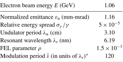
Table 1.Common simulation parameters.
Electron beam energyE(GeV) 1.06 Normalized emittanceεn(mm-mrad) 1.16
Relative energy spreadσγ/γ 5×10⁻⁵
Undulator periodλu(cm) 3.10
Resonant wavelengthλr(nm) 6.19
FEL parameterρ 1.5×10⁻³ Modulation periods¯(in units ofλr)∗ 120
∗Only for mode-locked FELs.
Table 2.Specific simulation parameters.
Undulator section length¯l(in units ofλu) 24
Peak currentI(kA) 1.0
Number of undulator sections (SASE FEL) 30
Number of undulator/chicane modules before saturation (Mode-locked FEL) 21
Modulation amplitude (MeV)a 1.06
aOnly for mode-locked FEL.
upon z¯. Each cubic equation is seen to be the usual dispersion equation describing the (uncoupled) linear solution at frequencies ω¯ =0,±1ω¯ [5]. A further, more lengthy, analysis may be carried out using the method of Laplace transforms to obtain full solutions of the coupled system and this will be the subject of a future work.
5. Simulation results
5.1. Mode locking using energy modulation
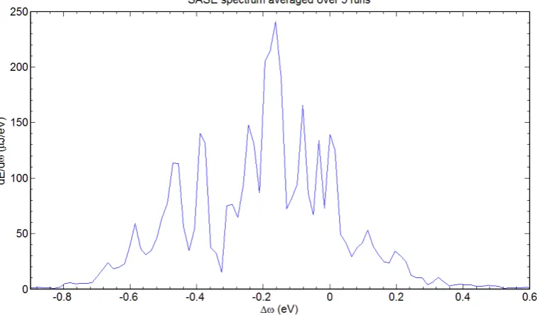
In what follows we present simulation results obtained with the two-dimensional FEL code Ginger [7] for a mode-locked FEL where mode locking was based on the beam energy modulation. We compare these results with similar simulations for a SASE FEL. The SASE and mode-locked FEL simulations had identical beam and undulator parameters, except that in the SASE case we did not use an energy modulation and simple drifts were chosen instead of magnetic chicanes to ensure unperturbed FEL interaction in the sequence of undulator sections. The parameters used in the simulations are given in tables1and2, where in table1we gathered a subset of parameters that remained unchanged in all simulations presented here and in the following subsection. Figures 3 and 4 show the results obtained for a SASE FEL. Figures 5
and6show the results obtained for a mode-locked FEL. These results confirm previous findings in [1].
The FWHM of the SASE spectral peak is given by 1ω/ωr≈2 √
ρ/Ntot [4, 8, 9], where Ntot is the total number of undulator periods in the FEL. The FWHM of the entire spectrum
[image:11.595.146.478.301.376.2]Figure 3.SASE output power, averaged over five runs, after passing through the FEL design shown in figure 1, but without the chicanes placed in between the undulators.
Figure 4.The SASE spectrum averaged over five runs, after passing through the undulator design shown in figure1, but without chicanes placed in between the undulators.
defines a single undulator spectrum, as in equation (6), i.e. 1ω/ωr≈1.2/Nu. Calculations
[image:12.595.150.529.403.625.2]Figure 5. The mode-locked FEL output power averaged over five runs. Mode locking was obtained by an energy modulation of the beam.
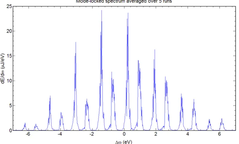
Figure 6.The mode-locked FEL output spectrum averaged over five runs. Mode locking was obtained with energy modulation of electrons.
[image:13.595.147.533.404.636.2]Table 3.Specific simulation parameters for longer undulator.
Undulator section length¯l(in units ofλu) 48
Peak currentI(kA) 1.0
Number of undulator/chicane modules before saturation 17
Modulation amplitude (MeV) 1.06
Figure 7. Mode-locked FEL output power averaged over five runs. Each undulator section is twice as long as that used to generate the data for figures5
and6(48 periods instead of 24). The delay introduced by the chicane is reduced accordingly.
spectral power in the mode-locked spectrum and can be seen by comparing the spectral peaks of figure4with figure6.
Although the peak spectral brightness drops in the mode-locking FEL, there are still some benefits to the mode-locked spectrum. Each individual mode in figure 6is typically narrower than that of the SASE spectrum in figure4. Thus, for applications involving narrow bandwidths, the radiation will contain fewer unwanted photons. Additionally, control is obtained over the total width of the output spectrum, which is dependent on the number of undulator periods in the individual undulator sections.
To verify that the width of the mode-locked spectrum is indeed inversely proportional to the number of undulator periods in a single module, a simulation was run with an undulator length twice that of above, using simulation parameters given in table 3. Figure 7 shows a typical series of short pulses where two patterns discussed previously are clearly seen and figure 8
[image:14.595.148.531.213.453.2]Figure 8. Mode-locked FEL spectrum averaged over five runs for the longer undulator case. Note the decrease in the FWHM of the entire spectrum with the increased undulator length. The FWHM drops by about a factor of two as the undulator length doubles.
5.2. Mode locking using peak current modulation
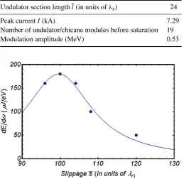
Table 4.Specific simulation parameters for peak current modulation.
Undulator section length¯l(in units ofλu) 24
Peak currentI(kA) 7.29
Number of undulator/chicane modules before saturation 19
Modulation amplitude (MeV) 0.53
Figure 9. Peak spectral brightness as a function of the slippage in the first undulator/chicane module. Dots show simulation results and the curve is used as a guide for the eye.
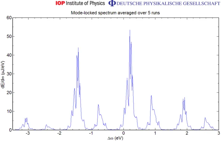
Table 4 gives FEL parameters used in the simulation for current modulation with the optimized slippage in the first undulator/chicane module. The peak current of 7.3 kA is that of a current spike and is significantly larger than a 1 kA peak current in previous simulations for examples with electron energy modulation. Figure 10 shows the output spectrum and demonstrates the anticipated higher spectral brightness over the energy modulated example in figure6by an approximate factor of seven.
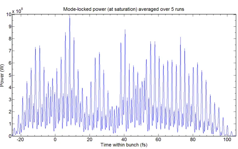
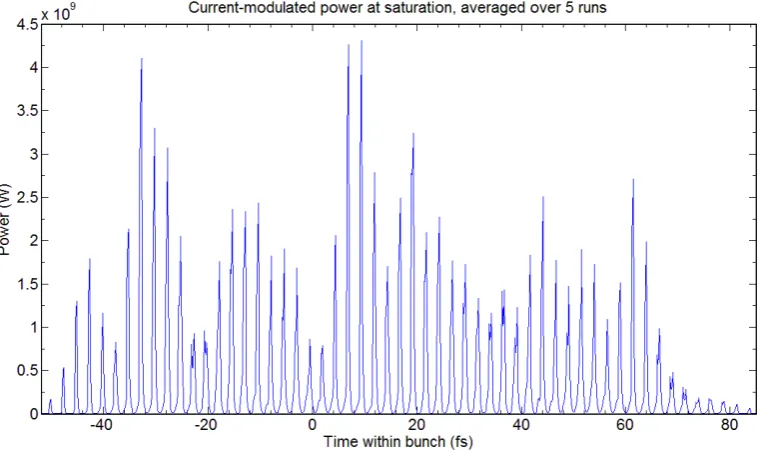
In addition to this enhanced spectral brightness, the secondary, interleaved modes that were present in the energy modulated mode-locked case have been eliminated. Despite the fact that there was an initial energy modulation in the beam, the correlation between beam energy with position along the modulation period is effectively destroyed in the first magnetic chicane. Most of the electrons are concentrated within the current spike (albeit with a larger energy spread due to the initial energy modulation). This spike is where the FEL interaction is strongest and where most of the radiation power is produced. Comparison of the case of figure11with mode locking via current modulation, and the case of figure 5with mode locking via the energy modulation shows that current modulation also gives a clean temporal separation of the radiation pulses spaced at the modulation period.
5.3. Broad bandwidth FEL
Figure 10. Mode-locked FEL output spectrum averaged over five runs. Mode locking was done using electron beam current modulation.
Figure 11. The mode-locked FEL output power averaged over five runs. Mode locking was achieved using electron beam current modulation.
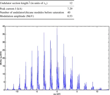
[image:17.595.149.529.395.620.2]Table 5.Specific simulation parameters for peak current modulation.
Undulator section length¯l(in units ofλu) 12
Peak currentI(kA) 7.29
Number of undulator/chicane modules before saturation 40
Modulation amplitude (MeV) 0.53
Figure 12. Mode-locked FEL output spectrum of the shorter (12 period) undulator, averaged over five runs. Mode locking was obtained using current modulation, with each undulator section one-half the length of that used in the standard energy and current modulated beam studies of tables 2 and4 and figures5,6,10and11.
Thus, for an undulator section with, say, only 10 periods, the spectral width may therefore be 10–20 times broader than that of a typical SASE FEL. Confirming this, figure 12 shows the simulation result where the undulator length was reduced to 12 periods and the number of undulator/chicane modules was increased to 40 modules (see table 5), while keeping all other parameters the same as in the current modulated mode-locked FEL simulation of the previous section. As expected, the bandwidth was doubled and the peak spectral brightness was halved compared to the previous case in figure10that had a two times longer undulator section.
6. Conclusion
beam energy modulation. It was shown that mode locking using current modulation improves spectral brightness of the source and purity of the series of short pulses, providing a clean sequence of pulses separated by the period of the electron beam current modulation. It was also shown that the mode-locked FEL can generate tunable x-ray radiation with a broad comb-like spectrum comprised of many modes, with each mode being of a relatively narrow bandwidth when compared to that of a SASE FEL spectrum. This type of FEL may be of interest for time-resolved pump–probe experiments with short x-ray pulses where simultaneous probing of a sample over a wide spectral range is essential. It was found in numerical simulations that a mode-locked FEL tuned to the central wavelength of 6.2 nm may have spectral brightness of the order of 30–180µJ eV−1 per pulse. At the time of writing, this brightness exceeds by many orders of magnitude the peak spectral brightness of any other x-ray source capable of a similar bandwidth, e.g. the high-order laser harmonic generation and bending magnet of a third-generation, storage ring-based synchrotron light source.
Acknowledgments
EK and AZ are grateful to W Fawley for many useful discussions and help with GINGER code. This work was supported by the US Department of Energy, Office of Science, Office of Basic Energy Sciences, under contract no. 06CH11357 and contract no: DE-AC02-05H11231.
References
[1] Thompson N R and McNeil B W J 2008Phys. Rev. Lett.100203901
[2] Siegman A E 1986Lasers(Sausalito, CA: University Science) see chapter 27 [3] Berlasso Ret al2006Phys. Rev.B73115101
[4] Bonifacio R, McNeil B W J and Pierini P 1989Phys. Rev.A404467
[5] Bonifacio R, Pellegrini C and Narducci L 1984Opt. Commun.50373
[6] Dunning D J, Thompson N R, Williams P H and McNeil B W J 2009MOPC 69, Proc. of the FEL2009
(Liverpool, UK) p 165
[7] Fawley W 2001 LBNL Technical Report 49625 [8] Kim K J 1986Phys. Rev. Lett.571871
[9] Bonifacio R, de Salvo L, Pierini P, Piovella N and Pellegrini C 1994Phys. Rev. Lett.7370
![Figure 1. A schematic of an FEL design with mode-locking capabilities, asshown in [1]](https://thumb-us.123doks.com/thumbv2/123dok_us/1685068.121895/4.595.73.534.116.176/figure-schematic-fel-design-mode-locking-capabilities-asshown.webp)
![Figure 2. Theoretical time-domain (left) and frequency-domain (right) plots ofthe electric field amplitude at the output of a conventional laser cavity oscillatorwith round trip time T = 1.51 (in arbitrary units), as in [2]](https://thumb-us.123doks.com/thumbv2/123dok_us/1685068.121895/5.595.147.530.76.505/figure-theoretical-frequency-electric-amplitude-conventional-oscillatorwith-arbitrary.webp)