1
IAC-08- C1.1.3
Spacecraft Formation-Flying Using Potential Functions
Ahmed Badawy
Department of Mechanical Engineering, Military Technical College, Cairo, Egypt [email protected]
Colin R McInnes
Department of Mechanical Engineering, University of Strathclyde, Glasgow, UK [email protected]
ABSTRACT
A group of small spacecraft able to change their relative position and attitude through the use of the potential function method is discussed. The spacecraft shapes, sizes and manoeuvring capabilities are not identical, although all are assumed to manoeuvre using continuous thrusters. A hyperbolic form of the attractive potential function is used to reduce actuator effort by using natural orbital motion to approaching the goal configuration. A superquadric repulsive potential with 3D a rigid object representation is then used to provide an accurate representation of the shape of spacecraft in the potential function. As the spacecraft start away from their goal, a parabolic attractive potential is inefficient as the control force increases with distance from the goal. Using a hyperbolic attractive potential, the control force is independent of the distance to goal, ensuring smooth manoeuvring towards the goal with a bound actuator effort.
INTRODUCTION
The concept of artificial potential fields was described initially for robot motion planning and manipulators by Khatib1. The original global potential field was composed of two independent functions, attractive and repulsive. As robotics technology advances, manoeuvring requirements become more demanding. Since the original work of Khatib modifications to the original potential function have been introduced in areas such as dynamic environments2,3, real object shapes4 and object rotations5,6. The attractive potential generates a goal configuration with a final specified position and orientation. Typically, the translational attractive potential has not been coupled to the rotational attractive potential. This coupling has been generated through the repulsive potential which can incorporate relative position and orientation for effective collision avoidance7,8,9. The repulsive potential should be defined whenever more than one manoeuvring object exists in the work
space. Many functions are suitable for obstacle representation such as FIRAS1, superquadric deformable functions4,10, Gaussian functions11, and Laplace functions12.
HYPERBOLIC ATTRACTIVE POTENTIAL
Minimum control activity, bounded actuator effort and global stability are key requirements for effective autonomous spacecraft control. These demands are satisfied using the hyperbolic form of the attractive potential function13. The hyperbolic function is smooth in the neighbourhood of its vertex, the specified goal point, ensuring stability at goal. In addition, the hyperbolic surface asymptotes to a cone away from the vertex enabling bounded actuator effort as will be seen later, Fig. 1.
The hyperbolic attractive potential function suitable for continuous control is defined as:
(
)(
)
(
)
q
q
r
r
r
r
r
r
.
2
and
,
,
,
ω.
.
2
1
.
1
.
1
ω
λ
λ
λ
λ
+
+
+
−
−
−
+
=
q v
G G
p att
V
&
&
(1)
where the constants
λ
pλ
vλ
qλ
define the controller gains for position, velocity, orientation, and angular velocity. The spacecraft attitude is defined through a set of quaternion parameters, q =⎡
q1 q2 q3⎤
Tomitting the forth term q4, while is the
spacecraft angular velocity vector.
[image:2.595.326.546.487.717.2]Adding spacecraft translational and angular velocity to the potential function in addition to the position and attitude allow the definition of control forces and torques. The spacecraft will be able to choose between translation, rotation, acceleration/deceleration to avoid collisions as it moves towards the goal. The stability analysis will be discussed later after adding collision avoidance terms, through obstacle potential functions.
Fig. 1 Hyperbolic-well attractive potential
RIGID BODY REPULSIVE POTENTIAL
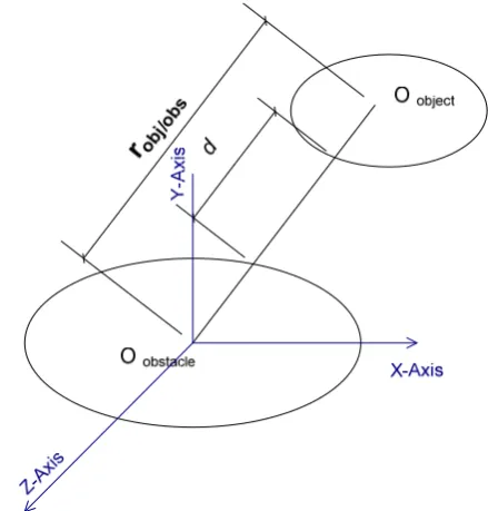
The spacecraft are represented as 3D rigid bodies using a superquadric repulsive model. This adds rotational control for collision avoidance. Following from previous work10, the distances between superquadric surfaces are defined, contradicting some calims that these distances are impossible to be estimated14. An approximate form for the radial separation distance d between surfaces, Fig. 2, is expressed as:
(
)
(
)
⎥⎦
⎤
−
⎢⎣
⎡ −
=
−
−
2
2
1
1
1
obj ,
obs ,
B , obj obj obj
B , obs obs obs obs
/ obj
,
F
,
F
*
d
ε
ε
x
a
x
a
r
(2)
The superquadric inside-outside function, F, is discussed in detail for some object shapes in ref. 8, while 1 is termed the superquadric
roundness parameter and a is a vector of geometric coefficients. The repulsive applied to the ith object is then expressed as9:
(
)
∑
≠ =
−
− −
−
= m
i j ,
j i,j
o i
, obs
d e e
A V
j , i d
i
1
2
1
α
(3)
σ
G
r r
where Ao is the maximum repulsive amplitude,
is the repulsive potential length-scale, and m
[image:2.595.54.282.578.739.2]is the total number of spacecraft.
GLOBAL POTENTIAL
The hyperbolic attractive potential function defined above is sufficient to bring spacecraft to their goal configuration at zero translational and angular velocity since this goal configuration represents the global minimum of the field. However, to brake when reaching the goal configuration requires some dissipative function. The definition of this dissipation function will be discussed later in the stability analysis of the global potential field.
The other consideration in the spacecraft formation is to generate a collision free path. This path will be generated on-line through the superquadric repulsive potential. The superquadric model is built using sensor data assuming that information on relative position and attitude is shared. Spacecraft with flat surfaces and straight edges can be modelled using superquadrics without local minima formation4,8. The global potential function of the ith spacecraft with m spacecraft in the formation is now defined as:
∑
+ + + + ⎟ ⎠ ⎞ ⎜ ⎝ ⎛ + − − = m ij obs i i i i q v i G i p i V V , 2 , . 2 . . 2 1 1 1 q q r r r r ωλ
λ
λ
λ
& &≠ = j i j 1,
(4)
The stability and global convergence of the proposed potential function leads to the following control laws8:
(
)
∑
≠ =∇
−
m i j , j ij , obs vV
11
λ
−
−
+
−
−
=
* iv i , G i v i , G i p i 2
1
λ
λ
r
r
r
r
r
r
&
&
&
(5-a)
⎟⎟ ⎠ ⎞ ⎜⎜ ⎛ ∇ + + − =∑
≠ = m i j , j ij , obs q i * i , i qi q V
1 4 2 1 Q q ω ω
λ
λ
λ
& ⎥ ⎥ ⎥ ⎦ ⎢ ⎢ ⎢ ⎣ − − = 4 1 2 1 4 3 q q q q q q Q⎝
λ
ω(5-b)
where
⎤ ⎡ q4 q3 −q2
(6-a)
⎡
⎤
Tz y x ∂ ∂ ∂ ∂
∂ ∂ =
∇
(6-b)
⎡
⎤
Tq
q q
q1 ∂ ∂ 2 ∂ ∂ 3
∂ ∂ =
∇
(6-c)
The control laws are active whenever the rate of change of the global potential function is more than some non-positive value named control trigger. If the trigger is zero, it performs as Lyapunov-like stability, while if negative, anticipation of control action is made.
CONTROL STRATEGY
Continuous control action is applied to bring the rate of change of the global potential function to be less than the control trigger at the end of a period of forced motion. This is followed by a coasting period in which natural orbital dynamics dominates the spacecraft motion. The duration of both intervals are determined online by the controller itself depending on the current state of the workspace. Two extreme cases are possible: purely impulsive motion in the case of no obstacles or other spacecraft, and continuous forced motion in case of a cluttered environment. The key advantage of the hyperbolic potential is its ability generate constant/zero control force over the entire workspace away from the goal position and the obstacles (due to its constant gradient), unlike other methods where control action grows with distance from the goal.
The superquadric repulsive potential used in this paper provides the following characteristics:
1. Its ability to represent various object shapes in a manner suitable for motion planning as it converges to the specific object shape near its edges while it converts to a sphere form at some distance from the object8.
2. The potential contours approximate the shape of the obstacle at its surface hence decreasing the occupied volume in the workspace, as shown in Fig. 3.
3. The dependency of the superquadric repulsive potentials on both position and orientation of the objects lead to their gradients being defined in terms of both position and quaternion parameters7.
ENHANCING THE REPULSIVE MODEL
The principle of potential field method as discussed in literature1 is based on the assumption that each obstacle is surrounded by a region of high potential repelling away other objects. Different methods can be used to define such regions to generate effective collision avoidance manoeuvres.
The superquadric repulsive potential enables good obstacle representation as it describes the obstacle real shape near its edges and provides spherically symmetric iso-distance surfaces away from obstacle edges, shown in Fig. 3. This property decreases local minimum formation which can occur due to overlapping fields with different shapes. In this section we aim to reduce controller interventions through eliminating repulsive potentials that have no effect on manoeuvring objects
If the manoeuvring object moves away from an obstacle, it is clear that these obstacles have no effect. However, other cases are of interest, especially the case of straight edged objects moving parallel to these edges. In this case, even if the manoeuvring object enters a domain affected by the repulsive potential, it should not change its path as a result of the presence of the obstacle.
Consider a manoeuvring object moving downward parallel to obstacle edge as shown in Fig. 3. The variation in iso-distance contour lines which effect the repulsive potential is small. Consequently, we consider discarding obstacles with a rate of change of repulsive potential less than some value. This method also serves, in eliminating distant obstacles who have a small effect on the manoeuvring object so we define:
r ij , obs m
ij , obs i
,
obs V V c
V =
∑
∀ & >i j , j=1 ≠
(7)
[image:4.595.323.555.64.252.2]where cr is the repulsive potential trigger constant. The added computational complexity of implementing this strategy is compensated by reducing the computational effort by discarding some obstacles in the workspace.
Fig. 3 Object moves parallel to obstacle edge
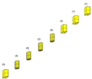
SPACECRAFT FORMATION
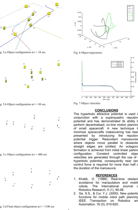
Eight small spacecraft are now located initially in some linear parking configuration with a 1 m separation distance between their centres. All object dimensions are chosen as 0.2 m. They are required to manoeuvre to form the vertices of an octagon. The spacecraft are classified into two distinct shapes, cuboids and cylinders, and ordered randomly as shown in Fig. 4. Successive manoeuvring is shown in Fig. 5 until the final configuration is achieved. The manoeuvres are only made with a repulsive potential trigger, , of 0.001. Object (1) moves in a straight line despite being between objects (7) and (8) as it moves parallel to their edges where the rate of change of their repulsive potential is less than .
r c
r c
The manoeuvring objects placed on a circular orbit of 300 km radius and are effected by natural orbital motion, Fig. 6. Constant object translational velocities are developed by use of the hyperbolic attractive potential, Fig. 7.
[image:4.595.366.528.586.725.2]
1 2 3 4 5 6 7 8 0.015
Fig. 5.a Object configuration at t = 34 sec
[image:5.595.65.547.51.786.2]Fig. 5.b Object configuration at t = 88 sec
Fig. 5.c Object configuration at t = 400 sec
Fig. 5.d Final object configuration at t = 1100 sec
-10 0
10 20
-10 0 10 20 30 -0.01 -0.005 0 0.005 0.01
z,
[
m
]
y, [m] x, [m]
Fig. 6 Object trajectories
0.14
0 100 200 300 400 500 600 700 800 900 1000 1100-0.02 0 0.02 0.04 0.06 0.08 0.1 0.12 x-direction
y-direction z-direction
time, [sec]
Ve
lo
c
it
y
,
[m
/s
e
c
]
Fig. 7 Object velocities
CONCLUSIONS
The hyperbolic attractive potential is used in conjunction with a superquadric repulsive potential and has demonstrated its ability to perform decentralised, on-line motion planning of small spacecraft. A new technique to minimize spacecrafts makeovering has been presented by introducing the repulsive potential trigger. Redundant manoeuvres, where objects move parallel to obstacles' straight edges are omitted. An octagonal formation is achieved from initial linear parking configuration. Constant controlled object velocities are generated through the use of a hyperbolic potential, consequently near zero control force is required for more than half of the duration of the manoeuvre.
REFERENCES
1. Khatib, O. (1986). Real-time obstacle avoidance for manipulators and mobile robots. The International Journal of Robotics Research, 5 (1), 90-98.
3. Ge, S.S., & Cui, Y.J. (2002). Dynamic motion planning for mobile robots using potential field method. Autonomous Robots, 13, 207-222.
4. Volpe, R., & Khosla, P. (1990). Manipulator control with superquadric artificial potential functions: theory and experiments. IEEE Transaction on Systems, Man, and Cybernetics, 20 (6), 1423-1436.
5. McInnes, C.R. (1994). Large angle slew manoeuvres with autonomous Sun vector avoidance. Journal of Guidance, Control and Dynamics, 17 (4), 875-877.
6. McInnes, C.R. (1995). Potential function methods for autonomous spacecraft guidance and control, AAS/AIAA Astrodynamics Specialist Conference, Halifax, Canada.
7. Badawy, A., & McInnes, C.R. (2006, October). Autonomous structure assembly using potential field functions. 57th International Astronautical Congress, Valencia, Spain, IAC-06-C1.P.3.04.
8. Badawy, A. (2007). On-orbit manoeuvring using superquadric potential fields. PhD Dissertation, University of Strathclyde. 9. Badawy, A., & McInnes, C.R. (2008).
On-orbit assembly using potential fields. Journal of Guidance, Control, and Dynamics, Vol. 31, No. 1, pp. 30-43.
10. Badawy, A., & McInnes, C.R. (2006a, August). Separation distance for robot motion control using superquadric obstacle potentials. International Control Conference, Glasgow, Scotland, paper no. 25.
11. McQuade, F. (1997). Autonomous control for on-orbit assembly using artificial potential functions. PhD Dissertation, University of Glasgow.
12. Roger, A.B., and McInnes, C.R. (2000). Passive-Safety Constrained Free-Flyer Path-Planning with Laplace Potential Guidance at the International Space Station. Journal of Guidance, Control and Dynamics, Vol. 23, No. 6, 2000, pp. 971-979.
13. Badawy, A., & McInnes, C.R. (2007b, July). Robot motion planning using hyperboloid potential functions. World Congress on Engineering, London, paper ICME 15. 14. Harden, T. (1997). The implementation of