City, University of London Institutional Repository
Citation:
Tsigkritis, Theocharis (2010). Diagnosing runtime violations of security and dependability properties. (Unpublished Doctoral thesis, City University London)This is the unspecified version of the paper.
This version of the publication may differ from the final published
version.
Permanent repository link:
http://openaccess.city.ac.uk/1181/Link to published version:
Copyright and reuse: City Research Online aims to make research
outputs of City, University of London available to a wider audience.
Copyright and Moral Rights remain with the author(s) and/or copyright
holders. URLs from City Research Online may be freely distributed and
linked to.
Department of Computing
Diagnosing Runtime Violations of
Security & Dependability Properties
Theocharis Tsigkritis
Submitted in fulfilment of the requirements for the degree of
Doctor of Philosophy in Computing at City University,
TABLE OF CONTENTS
LIST OF TABLES... 4
LIST OF FIGURES... 5
ACKNOWLEDGEMENTS ... 7
DECLARATION ... 9
ABSTRACT ...10
CHAPTER 1: INTRODUCTION ...11
1.1 OVERVIEW...11
1.2 THE NEED FOR DIAGNOSIS...11
1.3 DYNAMIC VERIFICATION AND DIAGNOSIS...12
1.4 THE DIAGNOSTIC APPROACH...14
1.5 CONTRIBUTIONS...14
1.6 OUTLINE OF THE THESIS...16
CHAPTER 2: RELATED LITERATURE...18
2.1 OVERVIEW...18
2.2 DYNAMIC VERIFICATION OF S&D PROPERTIES...18
2.2.1 Security and Dependability Properties: An Overview ...18
2.2.2 Dynamic verification ...20
2.3 ABDUCTIVE REASONING...64
2.3.1 Logic-Based Abduction...64
2.3.2 Temporal Abduction ...66
2.3.3 Selecting Abduced Explanations...67
CHAPTER 3: PRELIMINARIES...74
3.1 OVERVIEW...74
3.2 EVENT CALCULUS...74
3.3 THE EVEREST MONITORING FRAMEWORK...75
3.3.1 Specification of monitoring rules and assumptions in EVEREST...75
3.3.2 Standard EVEREST assumptions...79
3.4 THE DEMPSTER –SHAFER THEORY OF EVIDENCE...80
CHAPTER 4: EXTENDING EVEREST MONITORING FRAMEWORK FOR DIAGNOSIS ...85
4.1 OVERVIEW...85
4.2 BASIC FORMULATION OF THE DIAGNOSTIC PROBLEM AND ASSUMPTIONS...85
4.3 ECSPECIFICATIONS OF THE AIR TRAFFIC MANAGEMENT SYSTEM (ATMS)MOTIVATING EXAMPLE...89
CHAPTER 5: THE DIAGNOSTIC APPROACH...94
5.1 OVERVIEW...94
5.2 GENERATION OF EXPLANATIONS...96
5.2.1 The process of generating explanations ...96
5.2.2 Examples of explanation generation...102
5.3 IDENTIFICATION OF EXPLANATION EFFECTS...106
5.3.1 The process of identifying explanation effects ...106
5.3.2 Examples of explanation effects identification...116
5.4 PLAUSIBILITY ASSESSMENT...123
5.4.1 Foundations of the assessment ...124
5.4.2 Alternative explanations, expected consequences and search for supporting and refuting evidence for alternative explanations ...128
5.4.3 Event Genuineness...131
5.4.4 Efficiency of the Event Genuineness Assessment ...132
5.4.5 Reconsideration of Event Genuineness Formal Definition...155
5.5 DIAGNOSIS GENERATION...175
5.5.1 The diagnosis generation process...175
5.5.2 Examples of diagnosis generation ...177
5.6 MATHEMATICAL APPENDIX:PROOFS OF THEOREMS IN CHAPTER 5 ...177
CHAPTER 6: EXPERIMENTAL EVALUATION OF THE DIAGNOSTIC PROTOTYPE...207
6.1 OVERVIEW...207
6.2 EXPERIMENTAL SET UP OF LABORATORY SIMULATIONS...208
6.2.1 Architecture of the EVEREST diagnostic prototype ...208
6.2.2 The monitored system ...212
6.2.3 The deployed simulator...218
6.3 EVALUATION CRITERIA AND METRICS...222
6.3.1 Correctness metrics ...223
6.3.2 Responsiveness metrics...226
6.4 EVALUATION EXPERIMENTS DESIGN...228
6.4.1 The LBACS simulations ...229
6.4.2 Experimental configurations and evaluation experiments sets...232
6.5 EVALUATION EXPERIMENTS RESULTS...235
6.5.1 ExplanationConfiguration1 Experiments Results ...238
6.5.2 ExplanationConfiguration2 Experiments Results ...274
CHAPTER 7: OPEN RESEARCH ISSUES AND FUTURE WORK ...299
7.1 OVERVIEW...299
7.2 OPTIMIZATION OF THE DIAGNOSTIC PROTOTYPE...301
7.3 FURTHER EXPERIMENTATION...302
7.3.1 Extended adversaries capabilities experiments ...302
7.3.2 Extended belief function constants experiments ...303
7.3.3 Extended underlying monitoring theory experiments ...304
7.4 COMBINING DIAGNOSIS RESULTS...305
7.5 OTHER OPEN RESEARCH ISSUES...308
CONCLUSIONS...310
CHAPTER 8: ...310
8.1 OVERVIEW...310
8.2 SUMMARY OF THE RESEARCH WORK...310
8.3 MAIN NOVELTIES...312
8.4 LIMITATIONS...313
REFERENCES ...315
List of Tables
TABLE 2-1-SUMMARY OF FORMAL LANGUAGES USED FOR DYNAMIC VERIFICATION...34
TABLE 2-2–SUMMARY OF DYNAMIC VERIFICATION TOOLS...63
TABLE 3-1–AXIOMS OF EVENT CALCULUS...75
TABLE 3-2–MEDICAL PROBLEM DS BELIEF MEASUREMENTS...84
TABLE 5-1-BELIEFS IN GENUINENESS OF VIOLATION OBSERVATIONS OF RULE ATMS.R1 ...177
TABLE 6-1–TYPES OF SEED EVENTS GENERATED BY LBACSDEVICE...230
TABLE 6-2–INTER-EVENT DELAY RANGES FOR SIMULATED EVENTS...231
TABLE 6-3–LBACS CONDUCTED EXPERIMENTS...235
TABLE 6-4–EXAMPLE TABLE OF EGBT CORRECTNESS RESULTS...236
TABLE 6-5EXAMPLE TABLE OF VDT CORRECTNESS RESULTS...238
TABLE 6-6–EGBT CORRECTNESS RESULTS FOR EXPERIMENT EXPCONF1_1.5...239
TABLE 6-7-VDT CORRECTNESS RESULTS FOR EXPERIMENT EXPCONF1_1.5...240
TABLE 6-8-EGBT AND VDT RESPONSIVENESS RESULTS FOR EXPERIMENT EXPCONF1_1.5 ...242
TABLE 6-9-EGBT CORRECTNESS RESULTS FOR EXPERIMENT EXPCONF1_2.3 ...243
TABLE 6-10-VDT CORRECTNESS RESULTS FOR EXPERIMENT EXPCONF1_2.3...244
TABLE 6-11-EGBT AND VDT RESPONSIVENESS RESULTS FOR EXPERIMENT EXPCONF1_2.3 ...245
TABLE 6-12-EGBT CORRECTNESS RESULTS FOR EXPERIMENT EXPCONF1_2.5 ...246
TABLE 6-13-VDT CORRECTNESS RESULTS FOR EXPERIMENT EXPCONF1_2.5...248
TABLE 6-14-EGBT AND VDT RESPONSIVENESS RESULTS FOR EXPERIMENT EXPCONF1_2.5 ...249
TABLE 6-15-EGBT CORRECTNESS RESULTS FOR EXPERIMENT EXPCONF1_5 ...250
TABLE 6-16-VDT CORRECTNESS RESULTS FOR EXPERIMENT EXPCONF1_5...251
TABLE 6-17-EGBT AND VDT RESPONSIVENESS RESULTS FOR EXPERIMENT EXPCONF1_5 ...252
TABLE 6-18-EGBT CORRECTNESS RESULTS FOR EXPERIMENT EXPCONF1_7.5 ...253
TABLE 6-19-VDT CORRECTNESS RESULTS FOR EXPERIMENT EXPCONF1_7.5...254
TABLE 6-20-EGBT AND VDT RESPONSIVENESS RESULTS FOR EXPERIMENT EXPCONF1_7.5 ...256
TABLE 6-21-EGBT CORRECTNESS RESULTS FOR EXPERIMENT EXPCONF1_10 ...257
TABLE 6-22-VDT CORRECTNESS RESULTS FOR EXPERIMENT EXPCONF1_10...258
TABLE 6-23-EGBT AND VDT RESPONSIVENESS RESULTS FOR EXPERIMENT EXPCONF1_10 ...259
TABLE 6-24-EGBT CORRECTNESS RESULTS FOR EXPERIMENT EXPCONF2_10% ...275
TABLE 6-25-VDT CORRECTNESS RESULTS FOR EXPERIMENT EXPCONF1_10% ...276
TABLE 6-26-EGBT AND VDT RESPONSIVENESS RESULTS FOR EXPERIMENT EXPCONF2_10% ...277
TABLE 6-27-EGBT CORRECTNESS RESULTS FOR EXPERIMENT EXPCONF2_20% ...278
TABLE 6-28-VDT CORRECTNESS RESULTS FOR EXPERIMENT EXPCONF1_20% ...280
TABLE 6-29-EGBT AND VDT RESPONSIVENESS RESULTS FOR EXPERIMENT EXPCONF2_20% ...281
TABLE 6-30-EGBT CORRECTNESS RESULTS FOR EXPERIMENT EXPCONF2_30% ...282
TABLE 6-31-VDT CORRECTNESS RESULTS FOR EXPERIMENT EXPCONF1_30% ...283
List of Figures
FIGURE 2-1–CONCEPTUAL MODEL FOR DYNAMIC VERIFICATION...22
FIGURE 2-2–TAXONOMY OF MONITOR AND EVENT GENERATION FEATURES...23
FIGURE 2-3–TAXONOMY OF EVENT EMISSION METHODS...35
FIGURE 2-4–CONCEPTUAL REPRESENTATION OF ASPECT WEAVING [90]...37
FIGURE 2-5–A CLIENT-SERVER ARCHITECTURE [19] ...42
FIGURE 2-6–PROXY ARCHITECTURE [19]...42
FIGURE 2-7-THE MODEL-CARRYING CODE FRAMEWORK [144] ...47
FIGURE 2-8–THE JPAX ARCHITECTURE [75]...49
FIGURE 2-9–THE JAVA-MAC ARCHITECTURE [93] ...53
FIGURE 2-10–THE ARCHITECTURE OF JASSDA FRAMEWORK [25] ...55
FIGURE 2-11–THE JPFARCHITECTURE [166] ...58
FIGURE 2-12–RUNTIME VERIFICATION IN JNUKE [13] ...61
FIGURE 2-13–CLASSICAL APPROACH FOR DYNAMIC AND STATIC ANALYSIS [13] ...62
FIGURE 2-14-GENERIC ANALYSIS FOR BOTH A STATIC & DYNAMIC ENVIRONMENT [13] ...62
FIGURE 3-1–GRAMMAR FOR SPECIFYING BOUNDARIES OF TIME VARIABLES...77
FIGURE 5-1–THE OVERALL PROCESS OF THE DIAGNOSTIC APPROACH...94
FIGURE 5-2-ALGORITHM FOR GENERATING EXPLANATIONS OF ATOMIC PREDICATES...100
FIGURE 5-3–EVENT LOG FOR ATMS ...103
FIGURE 5-4–GRAPHICAL VIEW OF EXPLANATION GENERATION...106
FIGURE 5-5-ALGORITHM FOR COMPUTING THE TRANSITIVE CLOSURE OF DEDUCTIONS FROM ABDUCED PREDICATES...110
FIGURE 5-6–ALGORITHM FOR COMPUTING THE TRANSITIVE CLOSURE OF DEDUCTIONS FROM RECORDED EVENTS...114
FIGURE 5-7–STEP1 EXECUTED BY GENERATE_RE_CONSEQUENCES...120
FIGURE 5-8–STEP2 EXECUTED BY GENERATE_RE_CONSEQUENCES...121
FIGURE 5-9–STEP3 EXECUTED BY FLUENT MAINTENANCE MECHANISMS OF EVEREST...122
FIGURE 5-10–STEP4 EXECUTED BY GENERATE_AE_CONSEQUENCES...123
FIGURE 5-11–EVENTS AND EXPLANATIONS...134
FIGURE 5-12–ALGORITHM FOR HANDLING EFFICIENTLY EXPLANATIONS, CONSEQUENCES AND MATCHING RECORDED EVENTS...139
FIGURE 5-13–EVENT LOG FOR ATMS ...145
FIGURE 5-14–EXPLANATIONS/CONSEQUENCES TREE FOR EVENT E6...146
FIGURE 5-15–EXPLANATIONS/CONSEQUENCES TREE FOR EVENT E4 CONSIDERED AS MATCHING EVENT OF CONSEQUENCE C’E6,2,3...153
FIGURE 5-16-EXPLANATIONS/CONSEQUENCES TREE FOR EVENT E7 CONSIDERED AS MATCHING EVENT OF CONSEQUENCE C’E4,2,3...154
FIGURE 5-17–TIMELINE OF CAPTOR(EI)...166
FIGURE 5-18–FINAL DIAGNOSIS GENERATION ALGORITHM...176
FIGURE 6-1–OVERALL EVEREST DESIGN WITH RESPECT TO DIAGNOSTIC PROTOTYPE...209
FIGURE 6-2–EGBT ARCHITECTURE...211
FIGURE 6-3–VDT ARCHITECTURE...211
FIGURE 6-4–LBACS ARCHITECTURE...212
FIGURE 6-5–LBACS THEORY GRAPH PART I ...216
FIGURE 6-6-LBACS THEORY GRAPH PART II...217
FIGURE 6-7–LBACS SIMULATOR UML MODEL...220
FIGURE 6-8–LBACS SIMULATED COMPONENTS TOPOLOGY...221
FIGURE 6-9–ER,MONITOR AND EGBT TIMELINES...227
FIGURE 6-10-MONITOR AND VDT TIMELINES...228
FIGURE 6-11–EGBT CORRECTNESS RESULTS FOR EXPCONF1_1.5...240
FIGURE 6-12–VDT CORRECTNESS RESULTS FOR EXPCONF1_1.5...241
FIGURE 6-13–EGBT CORRECTNESS RESULTS FOR EXPCONF1_2.3...244
FIGURE 6-14–VDT CORRECTNESS RESULTS FOR EXPCONF1_2.3...245
FIGURE 6-15–EGBT CORRECTNESS RESULTS FOR EXPCONF1_2.5...247
FIGURE 6-16–VDT CORRECTNESS RESULTS FOR EXPCONF1_2.5...248
FIGURE 6-17–EGBT CORRECTNESS RESULTS FOR EXPCONF1_5...251
[image:6.612.107.518.105.736.2]FIGURE 6-19–EGBT CORRECTNESS RESULTS FOR EXPCONF1_7.5...254
FIGURE 6-20–VDT CORRECTNESS RESULTS FOR EXPCONF1_7.5...255
FIGURE 6-21–EGBT CORRECTNESS RESULTS FOR EXPCONF1_10...258
FIGURE 6-22–VDT CORRECTNESS RESULTS FOR EXPCONF1_10...259
FIGURE 6-23–EGBT_RECALLF RESULTS FOR DIFFERENT DIAGNOSIS WINDOWS WITH RESPECT TO LOW BELIEF RANGES...261
FIGURE 6-24-EGBT_RECALLF RESULTS FOR DIFFERENT DIAGNOSIS WINDOWS WITH RESPECT TO HIGH BELIEF RANGES...262
FIGURE 6-25-EGBT_PRECISIONF RESULTS FOR DIFFERENT DIAGNOSIS WINDOWS WITH RESPECT TO LOW BELIEF RANGES...263
FIGURE 6-26-EGBT_PRECISIONF RESULTS FOR DIFFERENT DIAGNOSIS WINDOWS WITH RESPECT TO HIGH BELIEF RANGES...264
FIGURE 6-27–EGBT_RECALLGRESULTS FOR DIFFERENT DIAGNOSIS WINDOWS WITH RESPECT TO LOW BELIEF RANGES...265
FIGURE 6-28-EGBT_RECALLGRESULTS FOR DIFFERENT DIAGNOSIS WINDOWS WITH RESPECT TO HIGH BELIEF RANGES...266
FIGURE 6-29-EGBT_PRECISIONG RESULTS FOR DIFFERENT DIAGNOSIS WINDOWS WITH RESPECT TO LOW BELIEF RANGES...267
FIGURE 6-30-EGBT_PRECISIONG RESULTS FOR DIFFERENT DIAGNOSIS WINDOWS WITH RESPECT TO HIGH BELIEF RANGES...268
FIGURE 6-31-VDT_RECALLF RESULTS FOR DIFFERENT DIAGNOSIS WINDOWS...269
FIGURE 6-32-VDT_PRECISIONF RESULTS FOR DIFFERENT DIAGNOSIS WINDOWS...270
FIGURE 6-33-VDT_RECALLG RESULTS FOR DIFFERENT DIAGNOSIS WINDOWS...271
FIGURE 6-34-VDT_PRECISIONG RESULTS FOR DIFFERENT DIAGNOSIS WINDOWS...272
FIGURE 6-35–EGBT BELIEF COMPUTATIONAL MEAN TIMES FOR DIFFERENT DIAGNOSIS WINDOWS...273
FIGURE 6-36-VDT BELIEF COMPUTATIONAL MEAN TIMES FOR DIFFERENT DIAGNOSIS WINDOWS...273
FIGURE 6-37–EGBT CORRECTNESS RESULTS FOR EXPCONF2_10% ...276
FIGURE 6-38-VDT CORRECTNESS RESULTS FOR EXPCONF2_10% ...277
FIGURE 6-39–EGBT CORRECTNESS RESULTS FOR EXPCONF2_20% ...279
FIGURE 6-40-VDT CORRECTNESS RESULTS FOR EXPCONF2_20% ...280
FIGURE 6-41–EGBT CORRECTNESS RESULTS FOR EXPCONF2_30% ...283
FIGURE 6-42-VDT CORRECTNESS RESULTS FOR EXPCONF2_30% ...284
FIGURE 6-43–EGBT_RECALLF RESULTS FOR DIFFERENT DELAYED EVENTS PERCENTAGES WITH RESPECT TO LOW BELIEF RANGES...286
FIGURE 6-44-EGBT_RECALLF RESULTS FOR DIFFERENT DELAYED EVENTS PERCENTAGES WITH RESPECT TO HIGH BELIEF RANGES...287
FIGURE 6-45-EGBT_PRECISIONF FOR DIFFERENT DELAYED EVENTS PERCENTAGES WITH RESPECT TO LOW BELIEF RANGES...288
FIGURE 6-46-EGBT_PRECISIONF RESULTS FOR DIFFERENT DELAYED EVENTS PERCENTAGES WITH RESPECT TO HIGH BELIEF RANGES...289
FIGURE 6-47–EGBT_RECALLGRESULTS FOR DIFFERENT DELAYED EVENTS PERCENTAGES WITH RESPECT TO LOW BELIEF RANGES...290
FIGURE 6-48-EGBT_RECALLGRESULTS FOR DIFFERENT DELAYED EVENTS PERCENTAGES WITH RESPECT TO HIGH BELIEF RANGES...290
FIGURE 6-49-EGBT_PRECISIONG RESULTS FOR DIFFERENT DIAGNOSIS WINDOWS WITH RESPECT TO LOW BELIEF RANGES...291
FIGURE 6-50-EGBT_PRECISIONG RESULTS FOR DIFFERENT DIAGNOSIS WINDOWS WITH RESPECT TO HIGH BELIEF RANGES...292
FIGURE 6-51-VDT_RECALLF RESULTS FOR DIFFERENT PERCENTAGES OF DELAYED EVENTS...293
FIGURE 6-52-VDT_PRECISIONF RESULTS FOR DIFFERENT PERCENTAGES OF DELAYED EVENTS...294
FIGURE 6-53-VDT_RECALLG RESULTS FOR DIFFERENT PERCENTAGES OF DELAYED EVENTS...295
FIGURE 6-54-VDT_PRECISIONG RESULTS FOR DIFFERENT PERCENTAGES OF DELAYED EVENTS...296
FIGURE 6-55–EGBT BELIEF COMPUTATIONAL MEAN TIMES FOR DIFFERENT PERCENTAGES OF DELAYED EVENTS...297
Acknowledgements
This thesis is the result of a long going process which revealed the author’s weaknesses and sensitivity to external phenomena. Therefore, the author would like to thank the people that supported, encouraged and assisted him to overcome all the occurred obstacles. Without these people, the present thesis would have not been existed.
Firstly, the author would like to extend his gratitude and appreciation to his supervisor and mentor, Professor George Spanoudakis. Professor G. Spanoudakis was constantly and patiently encouraging, supporting and revealing multiple ways for addressing any issues that happened to occur by respecting the author’s judgment and freedom of choice. His insistence and emphasis on analyzing, evolving and expanding thoughts and ideas was quite painful sometimes, however it was a way to awake the author’s focus and awareness when necessary. The discussions between Professor G. Spanoudakis and the author will be unforgettable for the author. For the short number of reasons mentioned above, author is honoured to have cooperated with Professor G. Spanoudakis.
In addition to his supervisor, the author would like to express his appreciation to his co-supervisor Dr. Christos Kloukinas for his valuable advices, his constant support and his relaxing way to discuss any emerged issue.
Two more people that the author would like to express his sincere thankfulness are Dr. Costas Lambrinoudakis and Dr. Stefanos Gkritzalis. Without their prompt and counsel, the author would have never embarked upon the adventure behind this thesis. The author would like also to give his thanks to Dr. Andrea Zisman for her support and concern especially in the last phase of the thesis preparation, and Dr. Artur d'Avila Garcez for his valuable comments during the initial stages of the research work presented in this thesis.
The author would like to thank the School of Informatics for the financial support for this research, as well, as the members of the Technical Support Team (TST) in the School of Informatics for their constant and tireless services.
Cysneiros Filho, Dr. Shant Narsesian, Mark Firman, Amalia, Andreas and Eirini Spyrou, Dr. Kelly Androutsopoulos, Dr. Jameel Syed, Anestis Benavidis, Dr. Vasiliki Efstathiou, Anna Thanou, Leonidas Skoutas, Dr. Davide Lorenzoli, Dr. Marco Comuzzi, Ricardo Contreras, Dr. Igor Siveroni, Kostas Poulios, Dr. Eirini Nedelkopoulou, Stavros Fakanas, and Stelios Papakonstantinou.
Besides all the aforementioned people, the author feels mostly obliged to his family. The author therefore is especially grateful to his parents, Athanasios and Loukia, for supporting him in any possible way, whether it was love or advice, wherever and whenever. Also, the author would like to express his sincere thankfulness to his brother and cousin, Petros T. and Petros P., whose joyfulness made author’s hard times smoother, and his aunt Marina, who hosted him in Kefallonia - a vitalising and rejuvenating piece of land for the author. It would be impossible for the author to overstate how valuable the contributions of his family were over these years.
Given the chance, the author would like to dedicate this thesis to his grandparents, who are not with him in this life anymore. The author dedicates humbly and equally this piece of work to the memory of Petros and Anastasia expressing his true gratitude for everything that had lavishly given to him, and to the memory of Theocharis and Sofia, even if the author did not have the chance to meet them alive and live with them. Both couples of author’s grandparents are always in author’s mind considered as the very origin of his life.
Declaration
Abstract
Chapter 1:
Introduction
1.1
Overview
Monitoring security and dependability (S&D) properties of software systems at runtime is widely accepted as a measure of increased resilience to dependability failures and security attacks, and several approaches have been developed to support it (see [99] for a survey). Whilst basic monitoring provides the core functionality for detecting violations of such properties, it cannot always provide the information that is necessary in order to understand the reasons that underpin the violation of a property and decide what would be an appropriate reaction to it.
In this thesis, we present a diagnosis system that we have developed as extension of a monitoring framework [109, 153, 155], called EVEREST (EVEnt REaSoning Toolkit).
EVEREST supports the specification and monitoring of properties expressed in Event
Calculus (EC) [149] as rules. The provision of diagnostic information is based on the
generation of alternative explanations for the events which are involved in the violations of rules, and the assessment of the plausibility of these explanations based on whether their effects correspond to events recorded during the operation of the monitored system as already presented in [162, 163, 164]. The key characteristic of our approach is the use of abductive reasoning [42, 122, 136] for the generation of explanations and belief based reasoning [146] for the assessment of explanation plausibility.
1.2
The need for diagnosis
To appreciate the need for diagnosing the reasons underpinning violations of security and dependability properties, consider an air traffic management system, referred to as ATMS in the following. ATMS uses different radars to monitor the trajectories of airplanes in different air spaces. It is also connected with a system that keeps a record of flight plans which are submitted by different planes ahead of flights to indicate the expected route of a flight and request flight permission.
areas covered by different radars. In such cases, to check the integrity of the information that is provided by the different radars which cover an airspace, we can monitor a rule requiring that if one of these radars sends a signal indicating that an airplane is in the airspace, every other radar that covers the same space should also send a signal indicating the presence of the plane in it within a certain time period of time after the receipt of the initial signal. Such a rule is violated in all cases where the monitor receives a signal event by one of the radars of ATMS that cover a specific airspace but not the other. Clearly, whilst in such cases, knowing that the rule has been violated is important for the operation of ATMS but the violation report on its own is not sufficient for establishing the reasons why the second expected signal was not received and taking appropriate action (if possible). In fact, the violation may have been due to several reasons, including the following:
• The radar that did not send the expected signal was malfunctioning (Cause 1).
• The communication link between the radar that did not send the expected signal and
the monitor was malfunctioning or an intruder captured the signal and prevented it from reaching the monitor (Cause 2).
• The radar that sent the expected signal was malfunctioning or its identity was faked by
an intruder that sent a fake signal to the monitor (Cause 3).
Although the above list of possible causes is not exhaustive, it demonstrates that a decision about what would be an appropriate reaction to the violation depends on the rea- son(s) that have caused it and, therefore, the selection of the appropriate response action cannot be made solely on the basis of knowledge about the violation but requires additional diagnostic information. Therefore, identifying which of the above reasons has caused the violation is important for taking actions that would restore the integrity of the operation of ATMS.
1.3
Dynamic Verification and Diagnosis
Section 1.2, dynamic verification solutions used in ATMS would be responsible to check at runtime the liveness of the radars connected to ATMS. In case that radar liveness violations are detected, diagnosis tools could be used for providing additional information by identifying the reasons have caused the detected violations.
However, in the context of software system dynamic verification, there are many approaches [22, 66, 128, 139, 161] that consider diagnosis as the identification of system observations, which resulted to a failure, fault or violation. For instance, in [22, 66, 128, 139, 161], synchronization of automata that model the expected behaviour of the monitored system and the generated event sets are used for carrying out diagnostic tasks. More specifically, Pencolé and Cordier [128] propose a decentralised fault diagnosis approach that synchronization of automata is performed for individual system components (fault detection at system components level), and then aggregated for the global system (fault detection at system level). Also, in both approaches given by Tripakis [161] and Bouyer et al. [22], the fault diagnosis problem is treated by generating algorithms (diagnosers) that act as fault detectors of internal faults for any given sequence of events generated by the system, which is modelled as a timed automaton [4].
In the present thesis, we assume a distinct separation between the dynamic verification task and the diagnosis task. The goal of monitoring task is the detection of inconsistencies with respect to the intended behaviour of a system with respect to some dependability properties. Therefore, the approaches [22, 66, 128, 139, 161] mentioned above could be considered as possible solutions to the monitoring task. An extended set of approaches that focus on system runtime monitoring, as for instance the work by Spanoudakis et al. [109, 153, 155] that the diagnostic approach presented in this thesis is built upon, are discussed below in the document, in particular in Chapter 2.
1.4
The Diagnostic Approach
The overall aim of the diagnostic approach this thesis presents is the identification of possible explanations for the violations of S&D properties [162, 163, 164] in order to aid the selection of appropriate reactions to these violations. To generate such explanations, the diagnostic mechanism uses abductive reasoning [42, 122, 136]. Then, following the identification of possible explanations, the diagnosis mechanism also assesses the plausibility of explanations by identifying any effects that they would have generated from the explanations and checking whether these effects correspond to observations that have occurred and are genuine. The assessment of the genuineness of the explanation effects and the validity of explanations is based on the computation of beliefs using functions that we have defined for this purpose. These functions have been defined using the axiomatic framework of the Dempster-Shafer theory of evidence [146].
The diagnostic framework has been designed as an extention of EVEREST monitoring framework described in [109, 153, 155]. EVEREST is able to monitor whether the behaviour of a system is consistent with tis intended behaviour in parallel with the operation of the monitored system without intervening with this operation in any form. In
EVEREST, the properties to be checked are specified as rules and ssumptions in a
language called EC-Assertion [109, 153, 155] that has its formal foundation in Event
Calculus [149]. EVEREST finally provides the infrastructure for storing properties violations and other observations occurring during the operation of the monitored system that are necessary inputs for the diagnostic process.
1.5
Contributions
The diagnostic approach this thesis presents is the result of the research work that evolved as shown throughout our earlier publicatations [162, 163, 164]. In these publications, the concept of event genuineness, as a criterion for event trustworthiness, and its assemssment mechanisms have been introduced and presented to the outer research world, starting from our initial intuitions, thoughts and formulations regarding diagnosis via event trustworthiness assessment and evolving to concrete evidential mechanisms in the same direction. What is presented in this thesis is the latest version of the aforementioned concept and its assessment mechanism after reconsiderations and corrections have been made. The main contributions of our research work are as follows:
The diagnostic framework firstly presented in [162, 163, 164] and discussed in this thesis is designed to identify possible explanations for runtime S&D violations rules specified in Event Calculus [149] in order to aid the selection of appropriate reactions to these violations. The violations of S&D properties are detected by a non-intrusive monitoring1 framework [109, 153, 155] at the runtime
of the monitored system. The diagnostic framework processes the detected violations by taking into account other observations from the monitored system. The diagnostic information that is produced refers to the cause of the detected violations in terms of belief measurements in the genunieness of explanations effects and the validity of explanations that were generated for the examined violations.
• Abductive algorithm for generating explanations.
To compute the possible explanations of runtime violations of S&D properties specified in Event Calculus [149], an algorithm that reasons abductively on the observations involved in the examined violations has been devised (see Section 5.2.1 and [162, 163, 164]). Another key characteristic of the abductive algorithm is that it reasons on the temporal aspects of violation observations against the intended behaviour of the examined system by treating any occurring time constraint satisfaction problem as linear programming problem. The output of the algorithm is a list representing the alternative explanations for a particular violation observation.
• Deductive algorithm for identifying expected consequences.
To assess the plausibility and validity of the abductive explanations, the diagnosis process computes the explanations effects. For undertaking this task, a deductive algorithm that reasons on the abductive explanations against the intended behaviour of the system has been designed (see Section 5.3.1 and [162, 163, 164]). The deductive algorithm reasons again on the temporal aspects of the abductive explanations by treating any occurring time constraint satisfaction problem as linear programming problem. The output of the algorithm consists of
an exhaustive list of the observations that could be derived from the abductive explanations and the intended behaviour model of the system.
• Plausibility assessment scheme based on evidential reasoning.
An assessment scheme for observation genuineness based on the plausibility and correctness of the alternative explanations that are generated for a violation observation in the previous steps of the diagnostic process has been designed (see Section 5.4). As presented in [162, 163, 164], the assessment of explanation plausibility is based on the hypothesis that if the expected effects of an explanation match with observations that have occurred (and recorded) during the operation of the system that is being monitored, then there is evidence about the validity of the explanation. However, there is the possibility that we would not be able to confirm or disconfirm the validity of the explanation at the time that diagnostic process searches for evidence. To deal with this uncertainty, the diagnosis mechanism advocates an approximate reasoning approach which generates degrees of belief in the membership of observations in the log of the monitor and the existence of some valid explanation for it rather than strict logical truth values. These degrees of belief are computed by functions founded in the axiomatic framework of the Dempster-Shafer theory of evidence [146].
• Implementation of a diagnostic prototype.
A prototype based on the diagnostic framework this thesis presents has been implemented. The diagnostic prototype has been integrated with the underlying monitoring framework that is easy to set up and provides user flexibility in quite satisfying levels. The underlying monitoring framework extended with diagnostic capabilities allows the user to specify monitoring rules and assumptions of S&D properties and indicate whether diagnostic results are needed.
1.6
Outline of the Thesis
The rest of the thesis is structured as follows.
Chapter 2 presents a short literature review on abductive reasoning, as our diagnosis approach uses abductive reasoning as a technique for generating explanations that are used as diagnostic information.
Chapter 3 focuses on the theoretical background that underpins our diagnosis approach. More specifically, Chapter 3 presents the language that the reasoning mechanisms of our diagnosis approach use. Also, the monitoring framework, which the diagnosis approach in based on, is discussed by highlighting the formal specifications the framework uses. Finally, a short overview of the axiomatic framework that the diagnosis approach uses for handling uncertainty with respect to possible explanations of S&D violations on the basis of the available evidence is also provided.
Chapter 4 discusses the basic formulation of the diagnostic task as it is carried out by the presented diagnosis approach. The basic formulation is provided as formal specifications extensions to the monitoring framework that the diagnosis approach is based on. Having provided the basic formal characteristics of the diagnostic task, Chapter 4 concludes by presenting the formal specifications of the ATMS motivating example that is discussed in Section 1.2. This example is used in following chapters in order to demonstrate the technical aspects of the diagnosis approach.
In Chapter 5, a detailed description of our diagnostic approach is given. More specifically, we give an overview of the diagnosis process and describe in detail the algorithms and mathematical formulas used to carry out the forms of analysis which are used in the different stages of this process.
Chapter 6 presents the set up and results of an experimental evaluation of the diagnostic prototype that was implemented as a proof of concept for our diagnostic approach. The experimental evaluation has been based on the monitoring of a simulated case study.
Chapter 7 provides the reader with some of our insights regarding the open issues that emerged from our work in diagnosis of security and dependability properties violations.
Chapter 2:
Related Literature
2.1
Overview
The purpose of this chapter is firstly to give an overview of the notions of security and dependability properties from the perspective of software engineering and provide the readers with the technical background on security and dependability dynamic verification or runtime monitoring. Secondly, this chapter presents a short state of the art on abductive reasoningas a technique for generating explanations.
More specifically, Section 2.2 covers the technical background on dynamic verification or monitoring of system dependability and security by providing initially a short overview of the security and dependability properties themselves, mostly based on definitions given by Avizienis et al. [14]. Having provided definitions of security and dependability properties, we present critical analysis of current research on dynamic verification by presenting general purpose and security oriented dynamic verification approaches. We also present comparative discussion on the presented security and dependability dynamic verification lines of research.
Section 2.3 provides an overview of research in the area of abductive reasoning that it is a key characteristic of the approach presented by the present thesis. Therefore, by highlighting the basic aspects of abductive reasoning and the recent relevant research approaches, Section 2.3 aims to enable the reader to understand the relationship of our approach to abductive reasoning as a technique for generating explanations.
2.2
Dynamic Verification of S&D properties
The objective of this section is twofold: firstly to discuss about the notions of security and dependability properties, and secondly to provide a review of the state of the art in security and dependability dynamic verification or monitoring.
2.2.1
Security and Dependability Properties: An Overview
• Confidentiality is the ability to maintain the secrecy of data and the messages
exchanged between a system and its collaborating actors over communication channels.
• Integrity is the ability to ensure the accuracy and completeness of the data stored and the messages exchanged by a system. Maintaining integrity involves allowing only authorised users to change or create data and messages and applying controls to ensure the correctness of these messages and data.
• Availability is concerned with ensuring that access to a system is possible when
required.
• Non-repudiation is concerned with making it impossible for an entity that has
participated in some communication with a system to deny this participation. In message exchange, for instance, non- repudiation guarantees that the sender and the receiver of a message cannot deny the dispatch and receipt of the message, respectively.
• Authentication is the ability to determine whether an actor interacting with the system has the identity that it claims to have.
• Authorization is concerned with the assignment of the right permissions to an already authenticated entity.
• Privacy is the ability of a system to prevent personal information from becoming known to entities other than those which own the information or the information is about.
dependability. In the same context, we could generalise and consider that security properties are a subset of the dependability properties set, as the security properties of a system aim to prevent from unaccepted leak of private information (man in the middle attack [106]) and/or unaccepted delays in the deliverance of the provided services (denial of service attack [2]).
An important element in the above definition of dependability is the notion of "justifiable trust" which requires the ability to objectively verify that the delivered system service does not deviate from the required system behaviour and associated quality constraints. The development of system verification capabilities (i.e., the ability to verify that a system satisfies certain properties) has been the focus of significant research over the last few decades and has resulted in the development of a wide spectrum of, typically tool-supported, methods that offer such capabilities. These methods are distinguished into
static and dynamic.
Static verification methods aim to show that the desired properties of a system will always hold based solely on the specification of the system without considering its actual run-time behaviour. Dynamic verification methods, on the other hand, aim to show that desired properties hold based on observation of the run-time behaviour of a system and its interactions with its operational environment.
Due to the fact that static verification is not the main area of interest of this thesis, we are not providing an overview of methods that fall in this category. On the other hand, a brief overview of the dynamic verification of systems is following in the rest of the sections of the chapter.
2.2.2
Dynamic verification
Dynamic verification enables a software system to improve its dependability (and therefore security) [14], by checking whether its behaviour satisfies specific dependability and security properties while it is running. This can be accomplished by a software module, which monitors the execution of the system and checks its conformity with the specification of the relevant properties. This module can be either an external or an internal module of the monitored system.
verification and testing of dynamically adapted entities cannot provide adequate results, each one for different reasons. Static verification is a formal method and can prove that a system (or to be more accurate its model) is correct but is very time consuming and demands substantial education and experience from practitioners. Testing [101] on the other hand is an informal method which cannot prove a system correct since it can never offer a complete coverage of all its possible executions but can be easily applied even from inexperienced practitioners.
Being situated somewhere between static verification and testing, dynamic verification techniques aim to achieve the benefits of both approaches, by merging testing and formal specification. Thus, dynamic verification is considered to be a formal method applied to the implementation of the system that avoids the pitfalls of ad hoc testing and the complexity of full blown static verification techniques (model checking, theorem proving).
Dynamic system verification has been investigated in the context of different areas including requirements engineering, program verification, safety critical systems and service centric systems.
According to literature on dynamic verification [20, 47, 75, 153], the basic stages of dynamic verification are: (i) the development of a formal specification of a system including various types of properties, like safety and security properties, (ii) the application of methods for capturing events of interest and (iii) checking for violations by a monitor which can verify whether the observed behaviour of a system satisfies the required properties.
behaviour of the system (events flow) against the indented system behaviour (formal specification).
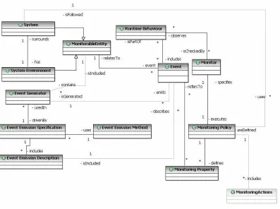
Figure 2-1 – Conceptual Model for Dynamic Verification
Figure 2-1 shows the conceptual model we have constructed to indicate the entities involved in dynamic verification. According to this model, the subject of dynamic verification that is signified by the class MonitorableEntity can be either a System or a
System’s Environment. Dynamic verification is carried out by a Monitor which observes the Runtime Behaviour of a system or its environment. The RuntimeBehaviour is a set of
events generated during the operation of the monitorable entities. These events are
generated by one or more Event Generator according to different Event Emission
Specifications. An event emission specification describes the particular Event Emission
Method to be used and one or more Event Emission Descriptions, which describe the exact types of events which should be generated. The observation of the events in a
Runtime Behaviour by the Monitor is carried out according to a specific Monitoring
Policy which specifies the Monitoring Properties that should be verified at runtime and
Figure 2-2 presents a taxonomy of monitor and event generation features. This taxonomy has three layers which differentiate monitoring and event generation capabilities according to (a) the controlling capabilities of a monitor, (b) the time of the event emission with respect to the occurrence of the action described by the event, and (c) the communication type between the monitor and the system.
Figure 2-2 – Taxonomy of Monitor and Event Generation Features
More specifically at the first layer a distinction is made based on whether the monitor has observation only, observation and control or control only capabilities. These capabilities can be summarised as follows:
• Observation (O): The monitor observes the runtime behaviour of the system by receiving the generated events and it checks whether the monitoring properties hold at runtime.
• Control (C): The monitor forces the system to execute actions without needing to
observe the actual state of the system. This class is also known as open-loop control.
The second layer of the taxonomy presents a distinction according to the time of the event emission with respect to the occurrence of the action described by the event. According to the criterion, we can distinguish between two cases:
• Emission preceding the action (pre): The event precedes the action which it describes. For example, the event generator sends an event to the monitor informing it that the system wishes to lock some resource before the system locks it.
• Emission posterior to the action (post): The event follows the action which it
describes. For example, the event generator sends an event to the monitor informing it that the system has completed some transaction.
Finally, the third layer of the taxonomy refers to the type of the communication between the monitored system and the monitor. According to this criterion, we distinguish between the following two types of communication:
• Synchronous communication (S): The event generator uses a blocking send
primitive to communicate with the monitor, waiting for a reply from it. This is only used when the monitor can exert control over the system.
2.2.2.1
Formalisation of Properties for Dynamic Verification
2.2.2.1.1
General Purpose Systems
In most of cases, the formal specification of the requirements that are to be dynamically verified is based on Linear Temporal Logic (LTL) [129] and variations of it including past and future time LTL (ptLTL and ftLTL respectively). Past and future time Linear Temporal Logics are modal logics for specifying properties of concurrent reactive systems and are used for analysing traces of execution of such systems. ptLTL provides temporal operators that refer to the past states of an execution trace, while ftLTL provides temporal operators that refer to the future/remaining part of an execution trace. In particular, the Temporal Rover (TR) tool [57] supports a future and past time Metric Temporal Logic (MTL). MTL [32] extends LTL with relative time and real time constraints. All four LTL future time operators can be constrained by relative time and real time constraints specifying the duration of the temporal operator. MTL constraints can specify lower bounds, upper bounds, and ranges for relative time and real time constraints.
In the context of monitoring oriented programming (MoP), any monitoring formalism can be added to the system. ptLTL, ftLTL and extended regular expressions (ERE), which can express patterns in strings in a compact way [145], have been used to formalise properties to be monitored [34]. The proposed algorithms use binary transition tree finite state machines (BTT-FSMs) to monitor ftLTL properties [34], as well as, formulas written in a logic based on EREs [145].
Havelund et al. [72, 73, 74] have developed several algorithms, which are relative to temporal logic generation and monitoring. For instance, they propose algorithms for past time logic generation by using dynamic programming [74]. Also they have used the MAUDE rewriting engine [37], for monitoring future time logic [72, 73] and have proposed algorithms that generate Büchi automata adapted to finite trace LTL [64].
of event expressions are similar to those used in modal logics like the π-calculus. HAWK
also supports extended regular expressions.
According to the concept of Design by Contract (DBC) technique, introduced by Meyer [112] as a built-in feature of the Eiffel programming language, specifications of pre-conditions and post-conditions can be associated with a class in the form of assertions and invariants and subsequently be compiled into runtime checks. Jass [115] and jContractor [1] are two Java-based DBC systems. Jass is a pre-compiler, which turns the assertion comments into Java code. The JASS sub-language for specifying trace-assertions is similar to CSP [78], and its syntax is more like a programming language. jContractor is implemented as a Java library which allows programmers to associate contracts, consisting of pre/post-conditions and invariants, with any Java class or interface.
Mahbub and Spanoudakis [109] have developed a framework for monitoring the behaviour of service centric systems which expresses the requirements to be verified against this behaviour in event calculus [149]. In this framework, event calculus is used to specify formulas describing behavioural and quality properties of service centric systems, which are either extracted automatically from the coordination process of such systems (this process is expressed in WS-BPEL) or are provided by the user.
In the area of component based programming Barnett and Schulte [19] have proposed a framework which uses executable interface specifications and a monitor to check for behavioural equivalence between a component and its interface specification. In this framework, there is no need for recompiling, re-linking, or any sort of invasive instrumentation at all, due to the fact that a proxy module is used for event emission. The component’s interface specifications are written in the Abstract State Machine Language (AsmL) [70], which is based on Abstract State Machines (ASM) [69]. This language is executable and supports non-deterministic specifications. Having native COM connectivity, one can not only specify and simulate components in AsmL but also substitute low-level implementations by high-level specifications. Specifications written in AsmL are operational specifications of the behaviour expected of any implementation. They provide a minimal model by constraining implementations as little as possible.
Robinson [137] has proposed a framework for requirements monitoring based on code instrumentation in which the high-level requirements to be monitored are expressed in KAOS. KAOS [48] is a framework for goal oriented requirements specification which is based on temporal logic. The KAOS modelling language can support all the phases of requirements acquisition and modelling, starting from initial functional and non-functional goals, formalising the meaning of such goals using temporal logic formulas and assigning the responsibility for the achievement of these goals to potential agents which may signify the system in question, systems that interoperate with it, and human actors interacting with the system. KAOS has also been used by Feather et al [61] in a framework that they have developed to monitor system requirements at runtime and which incorporates some capabilities regarding the reconciliation of requirements with the runtime system behaviour.
behaviour [22, 66, 128, 139, 161], diagnosis is carried through the synchronisation of automata modelling the expected behaviour of a monitored system and the events captured from it. Pencolé and Cordier [128] propose a similar but decentralised approach where synchronization is performed for individual system components and then aggregated for the global system.
The problem of fault diagnosis, concerning time, has been studied and analysed by Tripakis [161] and Bouyer et al. [22], where the system is modelled as a timed automaton. Timed automata extend the finite state machine model with real time clocks [4]. In both [22] and [161], the goal is the devising of algorithms (diagnosers) that would function as efficient online fault detectors of internal faults for any given sequence of observable events generated by the system. Tripakis has worked on the diagnosability of a timed system (plant). In particular, Tripakis has shown that the problem of checking whether a given timed system is diagnosable or not is a decidable problem and a diagnoser can be constructed as an online algorithm in case that the system is indeed diagnosable. The ∆-diagnosability diagnosis algorithm proposed by Tripakis is based on state estimation in order to decide whether a fault has occurred and report the fault at most ∆ time units after its occurrence, for a given set of observations. In particular, the ∆ -diagnosability algorithm keeps track of several possible control states and time ranges (zones) that the clock values can be in. The ∆-diagnosability problem for timed automata is PSPACE-complete. The complexity to diagnose faults from an observation is doubly exponential with respect to the final states of the system and to the size of the observations.
is a diagnoser realizable as an ERA, provided that the number of clocks and the set of constants are well defined and available to the diagnoser, is decidable and PSPACE-complete.
In [128], a decentralised model-based approach for diagnosing discrete event systems has been proposed. In particular, the proposed formal framework is based on communicating automata for computing online diagnosis of large discrete event systems. According to the authors, the diagnosis is defined as the identification of failure events and their propagations, which can explain the system observations. The system observations are split into temporal windows. For each temporal window, diagnosis (subsystem diagnosis) is performed for each well defined subsystem of the system. The subsystem diagnoses are, then, merged to build the overall diagnosis for the system (global diagnosis). Each subsystem is modelled as a communicating finite state machine. The explicit behaviour of each subsystem can be computed by using a synchronization operation, which is based on a transition system product [9] and applied to the component models of the subsystem.
2.2.2.1.2
Security Oriented Systems
Some of the logics and languages reviewed in the previous section have also been used either as they were initially proposed or with some semantic modifications and extensions for the formalisation of security properties. Naldurg et al [117], for instance, have proposed a framework for intrusion detection which takes advantage of the capabilities of the EAGLE language for specifying the attack-safe behaviour of a system. EAGLE is suitable for expressing temporal patterns that involve reasoning about the data values observed in individual events and thus it allows the description of attacks whose signatures appear to have statistical properties, e.g., password guessing or denial of service attacks. For such attacks there is no clear distinction between an intrusion and a normal behaviour and the detection of intrusions involves collecting statistics during runtime and using them to evaluate the probability of the occurrence of an attack.
operation sequences of the execution of one or more programs. For specifying such trace policies, Ko et al. [95] have developed a grammar, called "parallel environment grammar (PE-grammar)" whose alphabet consists of system operations. A PE-grammar can express various classes of security trace policies, including behaviour related to access to system objects, synchronization, and operation sequencing and race conditions in concurrent or distributed programs.
Schneider [143] has developed a system called Execution Monitoring (EM) which can monitor violations of security policies by monitoring the execution steps of a system. This system is based on the security automata of Alpern and Schneider [3], which are a special type of Büchi automata. EM also incorporates mechanisms that can terminate the system execution if it is about to violate its security policy. Following the same automata-based formalism, Ligatti et al [104] extended the control capabilities of security automata by proposing edit automata, which can remove and add letters (i.e., system actions) to the words (i.e. execution traces) they recognise.
Having proposed a security-policy enforcing model which follows the general dynamic verification approach, Bandara et al. [15] have specified a language based on Event Calculus to model the system behaviour and write security policy specifications. The form of EC, which is used in this work, was presented in [138] and consists of: (i) a set of time points (that can be mapped to the non-negative integers), (ii) a set of properties that can vary over the lifetime of the system (fluents), and (iii) a set of event types. System operations and domain-independent rules for policy enforcement were specified in this approach using these constructs. According to Bandara et al. [15], one can use EC to express system-models containing a combination of authorisation, obligation and refrain policies.
dynamic addition/deletion of rules or to select different sub-policies based on to the occurrence of an event or a time-out. An important reason of choosing ITL was the availability of an executable subset of the logic, known as Tempura [116]. The use of ITL, together with its subset of Tempura, offers the benefits of traditional proof methods with the speed and convenience of computer-based testing through execution and simulation.
Brisset [24] has worked on establishing and ensuring the correct operation of a Java platform security mechanism for runtime authorization of not trusted applications in remote hosts. The resulting Java security mechanism, which is called SecurityManager and belongs to the JAVA runtime library, essentially embodies the security policy of the virtual machine. The verification technique used a CTL-based language, which extends CTL with JVM-specific atomic propositions. Thus, JVM-specific atomic formulas can be used for runtime authorization of not trusted applications. In order to verify an application against these formulas its byte-code is translated into pre/post-condition generators for CTL formulas on-the-fly.
respective arguments. These uses, for instance “read(sensitive_file)”, augment the alphabet of EFSA with parameters to the initial system call names event alphabet. The resulting language is therefore able to distinguish the difference between the opening of a temporary file and the opening of a password file. Moreover, EFSA can also represent properties that refer to the arguments to system calls in the past, e.g. a program opens a file, whose name was given as an argument in the command line in the past.
For thoroughness we shall also mention certain higher-level languages and frameworks, which have been proposed for security requirements and policies. The KAOS framework, which we have already examined in the previous section on general-purpose formalisms, has been extended for modelling, specifying and analysing security requirements [166] by including the classical security concepts:
• Adversaries/attackers which are the malicious agents in the environment,
• Threats which are obstacles (anti-goals) intentionally set up by adversaries, and
• Assets, which must be protected against threats, are illustrated as passive or active
objects.
The Confidentiality, Integrity, Availability, Privacy, Authentication and
Non-repudiation requirements are sub-classes of the meta-class SecurityGoal in KAOS.
Finally, the formal first-order, real-time, linear temporal logic of KAOS has been augmented with epistemic operators (Knows, Belief), which are needed in security-related properties (e.g. Authorized, UnderControl, Integrity or Using predicates).
to cater for future types of policies and, rather than assuming a particular implementation platform, it could map to, and co-exist with, different underlying platforms.
In Service Oriented Computing, Baresi and Guinea [16] have proposed a framework for runtime monitoring of WS-BPEL processes. Monitoring rules are weaved at runtime into the process they must monitor and a proxy module supports their dynamic selection and execution [18]. Finally, they proposed a user-oriented language to integrate data acquisition and analysis into monitoring rules. Their monitoring rules define runtime constraints on WS-BPEL process executions and are expressed using the WSCoL language (Web Service Constraint Language). This development of this language has been inspired by the Java Modelling Language (JML) of Leavens, Baker and Ruby [100]. WS-CoL is a domain-independent policy assertion language for specifying user requirements (constraints) on the execution of Web services, which can be used within the framework of WS-Policy [142] and WS-Security [88]. WS-CoL is an assertion language augmented with features for allowing one to retrieve information that originates outside the process. It distinguishes between data collection and data analysis to differentiate the phase in which information is collected (data collection), from the phase in which this data is analysed (data analysis). Data can be collected from the process directly (e.g., values of internal variable) but they can also come from external sources (e.g., exchanged SOAP messages). An example of a monitoring rule in this language could specify that all exchanged messages must be encrypted using the 3DES encryption algorithm.
2.2.2.1.3
Summary of specification languages for security and other system
properties for dynamic verification
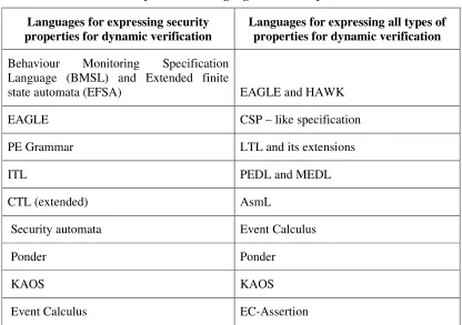
Table 2-1 gives a summary of various formal notations which have been used by different dynamic verification methods to express the properties to be verified and other functional and non functional characteristics of the systems and identifies languages and notations that have been specifically developed for expressing and verifying security properties.
Linear Temporal Logic (LTL) or extensions of it and languages with similar expressive power such as Event Calculus.
Table 2-1 - Summary of formal languages used for dynamic verification
Languages for expressing security properties for dynamic verification
Languages for expressing all types of properties for dynamic verification
Behaviour Monitoring Specification Language (BMSL) and Extended finite
state automata (EFSA) EAGLE and HAWK
EAGLE CSP – like specification
PE Grammar LTL and its extensions
ITL PEDL and MEDL
CTL (extended) AsmL
Security automata Event Calculus
Ponder Ponder
KAOS KAOS
Event Calculus EC-Assertion
Some dynamic verification techniques reason about systems at both low and high level of abstraction, such as Primitive Event Definition Language (PEDL) and Meta Event Definition Language (MEDL) in Java Monitoring and Checking (JavaMaC) framework [102]. PEDL is used for writing low-level specifications and is tightly related to the programming language, while MEDL specification makes use of primitive events and conditions in order to state high-level requirements.
2.2.2.2
Methods for Capturing Events
In the second stage of the general dynamic verification process, the goal is to apply techniques so as to capture the real behaviour of the system during its execution.
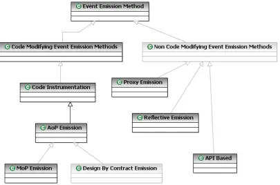
As shown in Figure 2-3, existing event emission methods can be divided into code
modifying and non code modifying ones. Code modifying event emission methods require
manually into the code of a system. Aspect Oriented Programming (AOP) has also been used to generate events (through the weaving of aspects into binary or source system code). AOP is a code modifying event emission method, which can be considered as a subcategory of code instrumentation. Monitoring Oriented Programming [34] and Design by Contract [112] are also code modifying event emission methods which can be regarded as subcategories of Aspect Oriented Programming [90].
[image:36.612.113.518.316.584.2]Non code modifying event emission methods generate events without altering the code of a system. Such methods access, modify and/or take advantage of capabilities of the general computational environment in which a system is executed, in order to generate the events flow. Reflective middleware approaches [30, 31, 110], proxy-based architectures [19] and the use of application programming interfaces (APIs) [12, 26, 109] constitute examples of event emission methods which belong to this category.
Figure 2-3 – Taxonomy of Event Emission Methods
2.2.2.2.1
Code-Modifying Event Capture Methods
The technique of code instrumentation can be described [137] as the insertion of statements into the system’s code (source or binary code) for monitoring purposes. Instrumentation can be done manually or automatically e.g. by using Jtrek-JSpy [65] or Joie [39] which automatically instrument Java byte code. During the execution of the instrumented code, an event stream is generated. The generated events can then be passed directly to external monitors or pre-processed before they reach the verification stage.
A tool using code instrumentation for capturing events in Java-based systems is RMon [137]. In Rmon, requirements are initially expressed in the KAOS framework [48], which provides a goal-oriented formal specification language based on temporal logic. Requirements are thus specified as high level goals which must be achieved by the system. These goals must then be mapped onto low-level events which can be monitored at runtime. The system’s code is then instrumented in order to capture these low level events, using the Joie framework [39].
In the initial phase of the Java MaC architecture [93], low-level specifications (written in PEDL) are inserted into the byte code of the monitored program through an automatic instrumentation procedure. Furthermore, in the MONID tool [117] system-level events are generated by appropriately instrumented source code.
2.2.2.2.1.2 Aspect Oriented Programming
behaviour. AOP proponents argue that disentangling crosscutting concerns leads to simpler development, maintenance, and evolution of software [90]. Examples of AOP approaches include AspectJ [91] and Hyper/J [159].
Figure 2-4 – Conceptual Representation of Aspect Weaving [90]
In particular, AspectJ [91] provides an approach to implementing cross-cutting features in Java. AspectJ provides a pattern mechanism, called pointcuts, for capturing groups of events, called joinpoints, that may occur during a program’s operation (such as method calls/receptions, constructor calls, field accesses, and exception events). The pattern matching mechanism includes regular expression matching, with wild-carding over fragments of method names, argument names, types etc. Extra code, called advices, can be associated with pointcuts, and is inserted by the AspectJ compiler into the join-points. Advices can inspect and modify data that are available at joinpoint events (e.g. method-call arguments and return values), and can create new data dynamically that is only shared with other advice.
For instance, Dingwall-Smith and Finkelstein [56] have developed an aspect oriented approach, in which system providers specify instrumentation code in separate classes, and define composition rules which determine how this code is to be merged with the application code, by using Hyper/J [159]. Also, Baresi and Guinea [17] have proposed a framework for runtime monitoring of WS-BPEL processes, in which monitoring rules are specified and weaved dynamically into the process they belong to. Furthermore, the instrumentation module of the JpaX framework performs a script-driven automated instrumentation of the program to be verified. JSpy [65] is the automated AOP environment package, which is used in JPaX [72, 75].
2.2.2.2.1.3 Design by Contract
Design by Contract (DBC), as proposed by Meyer [112] for the object-oriented language Eiffel, is a practical approach to runtime checking in applications. DBC is a lightweight formal technique, which allows one to add semantic information to a program by specifying assertions regarding the program's runtime state. Then, checks for specification violations are carried out at runtime. Such a technique stresses the importance of explicitly specifying the constraints that hold before (pre-conditions) and after a program is executed (post-conditions). The technique’s name refers to a contract, which is made between the client and the supplier of a system module and defines conditions before and after the execution of the module. Thus, for monitoring reasons the entry and exit points of the module become the events that we want to observe.

![Figure 2-4 – Conceptual Representation of Aspect Weaving [90]](https://thumb-us.123doks.com/thumbv2/123dok_us/1614977.114505/38.612.221.407.132.334/figure-conceptual-representation-aspect-weaving.webp)
![Figure 2-6 – Proxy architecture [19]](https://thumb-us.123doks.com/thumbv2/123dok_us/1614977.114505/43.612.216.400.72.140/figure-proxy-architecture.webp)
![Figure 2-7 - The Model-Carrying Code framework [144]](https://thumb-us.123doks.com/thumbv2/123dok_us/1614977.114505/48.612.125.507.173.416/figure-model-carrying-code-framework.webp)
![Figure 2-8 – The JPaX architecture [75]](https://thumb-us.123doks.com/thumbv2/123dok_us/1614977.114505/50.612.169.454.175.369/figure-the-jpax-architecture.webp)
![Figure 2-9 – The Java-MaC architecture [93]](https://thumb-us.123doks.com/thumbv2/123dok_us/1614977.114505/54.612.149.513.72.325/figure-the-java-mac-architecture.webp)