Near Infrared Spectroscopy for Fibre Based Gas Detection
George Stewart, Walter Johnstone, Graham Thursby, Brian Culshaw
Department of Electronic and Electrical Engineering University of Strathclyde
Royal College Building 204 George Street
Glasgow G1 1XW
ABSTRACT
Gas sensing systems based on fibre optic linked near infra red absorption cells are potentially a flexible and effective tool for monitoring accumulations of hazardous and noxious gases in enclosed areas such as tunnels and mines. Additionally the same baseline technology is readily modified to measure concentrations of hydrocarbon fuels – notably but not exclusively methane, and monitoring emissions of greenhouse gases. Furthermore the system can be readily implemented to provide intrinsically safe monitoring over extensive areas at up to ~250 points from a single interrogation unit.
In this paper we review our work on fibre coupled gas sensing systems. We outline the basic principles through which repeatable and accurate self calibrating gas measurements may be realised, including the recover of detailed line shapes for non contact temperature and / or pressure measurements in addition to concentration assessments in harsh environments. We also outline our experience in using these systems in extensive networks operating under inhospitable conditions over extended periods extending to several years.
INTRODUCTION
Fibre optic based systems for remote gas measurement are gradually emerging as significantly competitive prospects in the complex technological array of gas sensing technologies.
The reasons are many. Most electrical sensors for gas measurement are inherently electro chemical and subject to poisoning, contamination and drift over typically relatively short periods measured in months after which routine replacements are necessary. Additionally with all current technologies relatively frequent calibration checks are always needed. Further, these devices are almost always responsive to numerous gas species. They also all need local power supply and separate data transmission systems and frequently demand intrinsically safe electrical installation.
Optical systems are in total contrast. They can operate remotely and when fibre coupled can be linked over distances of many kilometers without electrical power supplies. Those based on laser spectroscopy are very much species specific and contamination and drift can be accommodated within processing algorithms located at a central control room. Additionally a single laser source can link to up to hundreds of sensing points each with sensitivity compatible with many applications, especially for explosive gases. The local optical power is very low so intrinsic safety is no longer an issue. Furthermore since network components are compatible with those used in fibre optic communications, installation procedures and installation economics are highly competitive.
In this paper we shall explore the prospects which fibre optic based systems offer for gas sensing using absorption spectroscopy, predominantly in the near infrared. We shall demonstrate a range of sensing systems and evaluate their performance characteristics. We believe the potential application benefits of such systems are significant though, in common with many fibre sensor technologies, these very positive features have yet to make their full impact into the user environment.
THE BASIC PRINCIPLES OF FIBRE OPTIC BASED SPECTROSCOPY
The most promising by far of the optical fibre compatible techniques for remote spectroscopy are based on tuneable diode laser absorption measurements, the essential features of which are shown in figure 1.
The output wavelength of a tuneable laser diode is scanned slowly (at a few Hertz) across a gas absorption line(1) and the
changes in attenuation as the output wavelength scans the line can be directly measured using the basic system conceptually above
Most (to all practical purposes all) convenient diode laser wavelength tuning mechanisms involve current tuning, which in turn through a combination of thermal changes in the cavity and injection current, modifies the optical dimensions of the cavity and therefore changes the output wavelength. Such changes are accompanied by a change in output intensity and hence the need for the reference channel shown in the figure.
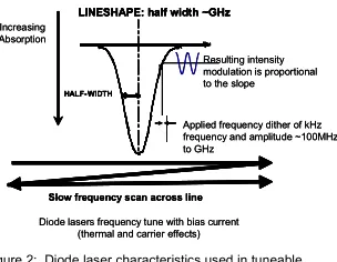
There are of course significant benefits to exploiting lock in detection through sinusoidally modulating the wavelength and detecting the resultant intensity modulation at the modulation frequency which corresponds closely to a measure of the slope of the absorption line, the integral of which gives the total absorption depth(2). Indeed some versions of this
technique focus more on the second derivative (which is represented by the second harmonic of the signal) and performing the double integral. (Figure 2) The concentration of the gas of interest is very simple to derive using the known spectral dependence of absorption depth which can be derived from a number of sources, most notably the HITRAN database.
Additionally the measurements which we have outlined above can in principle also provide information on the shape of the line. This in turn is linked through pressure and temperature broadening to the environmental conditions of the measurements which are usually inferred from other sources of information. This of course does assume that we can
Figure 1: Conceptual diagram - fibre coupled tuneable diode laser gas detection system
Laser Tuning
Laser Tuning
Gas cell
[image:2.612.218.370.477.595.2]divide Reference channel
Figure 2: Diode laser characteristics used in tuneable diode laser spectroscopy
LINESHAPE: half width ~GHz
HALF-WIDTH
LINESHAPE: half width ~GHz
HALF-WIDTH
Applied frequency dither of kHz frequency and amplitude ~100MHz to GHz
Resulting intensity modulation is proportional to the slope
Slow frequency scan across line Diode lasers frequency tune with bias current
(thermal and carrier effects) Increasing
Absorption
LINESHAPE: half width ~GHz
HALF-WIDTH
LINESHAPE: half width ~GHz
HALF-WIDTH
Applied frequency dither of kHz frequency and amplitude ~100MHz to GHz
Resulting intensity modulation is proportional to the slope
Slow frequency scan across line Slow frequency scan across line Diode lasers frequency tune with bias current
(thermal and carrier effects) Increasing
measure the line width and this is in practice relatively straightforward to implement using an optical resonator of known free spectral range and simply counting the frequency increments to calibrate the wavelength sweep. This leads to the more complete spectral measurement system shown in figure 3.
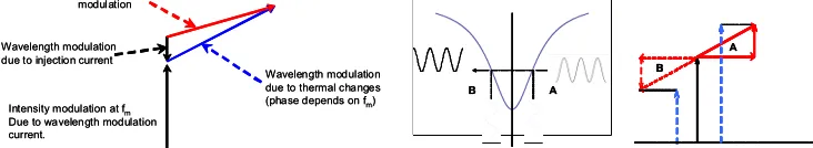
There is of course an additional complication. The current modulation which is introduced to produce the wavelength modulation also introduces an (unwanted) intensity modulation in phase with the current for most practical modulation frequencies. This residual intensity modulation at the frequency of interest can in principle be readily extracted through subtracting this as a reference from the signal which arrives at the lock in detector assuming of course that the intensity modulation caused by the wavelength scanning through the slope of the absorption line is in phase with this current induced intensity modulation.
In practice it isn’t(3). The wavelength modulation due to the applied sinusoidally varying of current has two components.
The first is due to carrier injection which tends to reduce the refractive index of the active resonant cavity thereby reducing the resonant wavelength. The second component is temperature modulation the dominant impact of which is to reduce the optical wavelength. The change in temperature which causes this effect varies in phase, thanks to thermal time constants, with the frequency at which the sinusoidal modulation is applied when compared to this thermal time constant which is typically in the millisecond to microsecond range. Consequently this phase differential between the sinusoidal modulation induced by the change in wavelength and in the sinusoidal intensity modulation induced by the change in current is to be accounted for in any subtraction process.
[image:3.612.170.447.132.221.2]Fortunately a reasonably robust approach to this subtraction process is relatively straightforward to implement, assuming that our lock in detection procedure includes both in phase and quadrature detection facilities. The essence of this approach can be gleaned from figure 4 which first of all shows the variation in phase and amplitude for the thermal component with frequency and secondly shows the phasor sums which are relevant for measurements of the first harmonic component taken at points with symmetrical slopes about absorption line centre. To a very good approximation these slopes are equal to each other but in antiphase. Consequently a simple “sum and difference” examination of the in-phase (with the driving intensity modulation) and quadrature components immediately gives the phase and amplitude of the absorption line slope induced components.
Figure 3: Basic system to track frequency increments via the optical resonator whilst monitoring gas cell transmission using wavelength
modulation spectroscopy and retaining a power reference level DFB
Laser 1:3 Split Cell
+ 10 kHz
4 Hz
Power Ref PD 1
PD 2 Lock-in Amp 10 kHzRef
X
A Filters HP
LP
Resonator PD 3
DFB
Laser 1:3 Split Cell
+ 10 kHz
4 Hz
Power Ref PD 1
PD 2 Lock-in Amp 10 kHzRef
X
A Filters HP
LP
Resonator PD 3
DFB
Laser 1:3 Split Cell
+ 10 kHz
4 Hz
Power Ref PD 1
PD 2 Lock-in Amp 10 kHzRef
X
A Filters HP
LP Resonator
Resonator PD 3PD 3
Figure 4: The phasor sum for the actual wavelength modulation resulting from current modulation (left), the intensity modulation resulting from applying this modulation at symmetrical points on the absorption line (centre)
and the extraction of the exact phase using in phase and quadrature detection in a lock-in amplifier (right)
Intensity modulation at fm
Due to wavelength modulation current.
Wavelength modulation due to injection current
Wavelength modulation due to thermal changes (phase depends on fm)
Resultant wavelength modulation
Intensity modulation at fm
Due to wavelength modulation current.
Wavelength modulation due to injection current
Wavelength modulation due to thermal changes (phase depends on fm)
Resultant wavelength modulation
A B
- 1. 01 0 1. 01
0 151
A B
- 1. 01 0 1. 01
0 151
A B
- 1. 01 0 1. 01
0 151
B B B
[image:3.612.119.485.540.607.2]The impact of this simple but very powerful tool is shown in the results in figure 5. Here we show measurements of the slope of the line as measured assuming the two components in phase as compared to the slope of the line as measured using this phasor decomposition method. We also include a comparison of the recovered line shape for the latter compared with standard data obtained from the HITRAN database. The agreement in the latter case is very good. The former case produces obvious distortion in line symmetry.
These measurements – which implicitly also use the resonator frequency counter – facilitate accurate measurements of linewidth as well as line absorption depth which in turn can give reliable measurements of pressure, assuming that the temperature is well characterised. In some cases these measurements can also form the basis of a combined pressure and temperature measuring system. For cooperative gas species the ratio of adjacent absorption line depths is a known function of temperature(4).
This then establishes the basis of a comprehensive tuneable diode laser spectroscopy technique capable of accurate and repeatable measurements of absorption depths and line widths. This technique can of course be applied in principle to any well behaved tuneable laser system which can be sinusoidally wavelength modulated. In the context of fibre based systems there are a few other constraints to consider, the most obvious of which is that the wavelengths at which the absorption spectroscopy should be implemented should also coincide with the transparent windows of the optical fibre. The most convenient prospects clearly lie in the region between around 0.7 and 2 microns. There are fortuitously numerous interesting species which have convenient absorption spectra in this range including methane, carbon dioxide, ethylene, ammonia, water vapour, hydrogen peroxide vapour, ethane, acetylene, carbon monoxide and hydrogen sulphide.. We clearly see that many of the gases of interest in safety and security applications are accessible using direct near infrared absorption spectroscopy. From an application perspective the question then is which of these are the most effectively addressed.
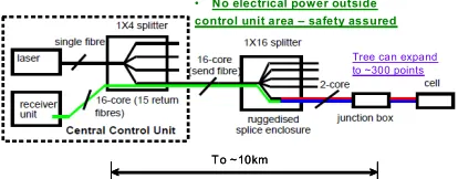
[image:4.612.67.546.134.256.2]A little more insight into the application prospects can be gleaned from a rapid overview of the system architectures which might be available. First and foremost a very high degree of system multiplexing is possible as indicated in figure 6. Furthermore this multiplexed system may be addressed from a single laser source over ranges covering many square kilometres and including up to a few hundred sensing points. This feature is particularly applicable to situations such as those found in mines, petrochemical plants and gas producing landfill sites.
Figure 5: Illustrating the efficacy of the phasor recovery technique outlined in figure 4 – the uncorrected multiple pressure measurements (left) show an asymmetry error, the corrected ones (centre) have eliminated this evident error whilst the typical
recovered data (right) demonstrates very good agreement with the predictions fomr the HITRAN data base
-0.3 -0.2 -0.1 0 0.1 0.2 0.3
1530.24 1530.29 1530.34 1530.39 1530.44 1530.49
Wavelength (nm) V o lt a g e ( A .U .)
0.257 bar (conventional) 0.506 bar (conventional) 0.78 bar (conventional) 1.021 bar (conventional) 1.273 bar (conventional)
-0.3 -0.2 -0.1 0 0.1 0.2 0.3
1530.24 1530.29 1530.34 1530.39 1530.44 1530.49
Wavelength (nm) V o lt a g e ( A .U .)
0.257 bar (conventional) 0.506 bar (conventional) 0.78 bar (conventional) 1.021 bar (conventional) 1.273 bar (conventional)
-0.2 -0.15 -0.1 -0.05 0 0.05 0.1 0.15 0.2
1530.24 1530.29 1530.34 1530.39 1530.44 1530.49
Wavelength (nm) V o lt ag e (A .U .)
0.257 bar (undistorted) 0.506 bar (undistorted) 0.78 bar (undistorted) 1.021 bar (undistorted) 1.273 bar (undistorted)
-0.2 -0.15 -0.1 -0.05 0 0.05 0.1 0.15 0.2
1530.24 1530.29 1530.34 1530.39 1530.44 1530.49
Wavelength (nm) V o lt ag e (A .U .)
0.257 bar (undistorted) 0.506 bar (undistorted) 0.78 bar (undistorted) 1.021 bar (undistorted) 1.273 bar (undistorted)
-0.3 -0.2 -0.1 0 0.1 0.2 0.3
1530.24 1530.29 1530.34 1530.39 1530.44 1530.49
Wavelength (nm) V o lt a g e ( A .U .)
0.257 bar (conventional) 0.506 bar (conventional) 0.78 bar (conventional) 1.021 bar (conventional) 1.273 bar (conventional)
-0.3 -0.2 -0.1 0 0.1 0.2 0.3
1530.24 1530.29 1530.34 1530.39 1530.44 1530.49
Wavelength (nm) V o lt a g e ( A .U .)
0.257 bar (conventional) 0.506 bar (conventional) 0.78 bar (conventional) 1.021 bar (conventional) 1.273 bar (conventional)
-0.2 -0.15 -0.1 -0.05 0 0.05 0.1 0.15 0.2
1530.24 1530.29 1530.34 1530.39 1530.44 1530.49
Wavelength (nm) V o lt ag e (A .U .)
0.257 bar (undistorted) 0.506 bar (undistorted) 0.78 bar (undistorted) 1.021 bar (undistorted) 1.273 bar (undistorted)
-0.2 -0.15 -0.1 -0.05 0 0.05 0.1 0.15 0.2
1530.24 1530.29 1530.34 1530.39 1530.44 1530.49
Wavelength (nm) V o lt ag e (A .U .)
0.257 bar (undistorted) 0.506 bar (undistorted) 0.78 bar (undistorted) 1.021 bar (undistorted) 1.273 bar (undistorted)
-0.3 -0.2 -0.1 0 0.1 0.2 0.3
1530.24 1530.29 1530.34 1530.39 1530.44 1530.49
Wavelength (nm) V o lt a g e ( A .U .)
0.257 bar (conventional) 0.506 bar (conventional) 0.78 bar (conventional) 1.021 bar (conventional) 1.273 bar (conventional)
-0.3 -0.2 -0.1 0 0.1 0.2 0.3
1530.24 1530.29 1530.34 1530.39 1530.44 1530.49
Wavelength (nm) V o lt a g e ( A .U .)
0.257 bar (conventional) 0.506 bar (conventional) 0.78 bar (conventional) 1.021 bar (conventional) 1.273 bar (conventional)
-0.2 -0.15 -0.1 -0.05 0 0.05 0.1 0.15 0.2
1530.24 1530.29 1530.34 1530.39 1530.44 1530.49
Wavelength (nm) V o lt ag e (A .U .)
0.257 bar (undistorted) 0.506 bar (undistorted) 0.78 bar (undistorted) 1.021 bar (undistorted) 1.273 bar (undistorted)
-0.2 -0.15 -0.1 -0.05 0 0.05 0.1 0.15 0.2
1530.24 1530.29 1530.34 1530.39 1530.44 1530.49
Wavelength (nm) V o lt ag e (A .U .)
[image:4.612.319.542.567.629.2]0.257 bar (undistorted) 0.506 bar (undistorted) 0.78 bar (undistorted) 1.021 bar (undistorted) 1.273 bar (undistorted)
Figure 7: detecting several gases simultaneously using a single fibre and cell network with multiple laser diodes each tuned to a separate species (e.g. methane, carbon dioxide). Clearly this concept also extends immediately to
multiple cells ligh t o ut to c ell
λ1
λ2
λ3
λ4 L ase r d io des, diffe r e nt w ave le ngth s
for eac h gas
W avele ngth m ultip le xor
ce ll F ib re link s
P r oc e ssing – se ries or p ar a llel for gas S pec ie s as ne ed e d
p hotod io de
o utp uts ligh t o ut to c ell
λ1
λ2
λ3
λ4 L ase r d io des, diffe r e nt w ave le ngth s
for eac h gas
W avele ngth m ultip le xor
ce ll F ib re link s
P r oc e ssing – se ries or p ar a llel for gas S pec ie s as ne ed e d
p hotod io de
o utp uts
Figure 6: Network architectures for fibre coupled gas detection systems
To ~10km To ~10km
• No electrical power outside
control unit area – safety assured
[image:4.612.73.280.575.656.2]The option on system architectures has a second dimension, namely that the same overall system can be utilised to address several gases by using an array of appropriately chosen tuneable diode laser sources. These can even be all addressed simultaneously using suitable wavelength multiplexing components (Figure 7) together with identifiable modulation frequencies for each of the laser diodes or alternatively sharing single modulation frequency and switching the sources using a simple optical switch. For typical applications – some of which we explore in more detail below – system update times measured in a few seconds can be readily achieved for every sensor throughout the array.
Self calibration and automatic integrity checking are additional features of the network concept. A reference cell within the network can be very conveniently located within the control room area and safe concentrations of the target gas (say methane) can be introduced to this cell on an occasional basis to check that the modulation depths and wavelength scanning systems within the interrogation laser are within calibration. This calibration can be undertaken either on a continuous basis if desired or at periods of a few weeks or months. In practice we have found the latter to be satisfactory. Furthermore the zero point on each cell is recalibrated on every wavelength sweep since the sweep is designed to take the measuring wavelength into areas outside the absorption line concerned therefore establishing the zero. A failed cell is automatically identified since that particular cell records zero optical transmission. These self checking and central self calibration facilities are unique to this particular system concept.
SOME SYSTEM EXAMPLES
The systems which we describe here all have their origins in some early work in which we endeavoured to demonstrate that a distributed sensing system based on a D shaped fibre could be used as the core of a safety monitoring installation for use in mines and tunnels(5). As a basic criterion this involved detecting a five metre cloud of methane gas in air at
about 1% concentration level. In principle it all worked. The practical implementation however was impeded by the availability (or lack of) a specific D shaped fibre with evanescent wave coupling into the air around it through the flat section of the D. It was also difficult to identify suitable packaging for structure in the environment for which it was intended whilst ensuring that the evanescent wave coupling was calibrated and consistent both throughout the lifetime of the fibre and throughout the length of the sensor. In this context the concept of evanescent wave gas sensing over a long distance proved impractical but more recently such systems using multimode large core fibre with intermediate
chemically active evanescently coupled coatings have – for some species which are as it happens complementary to the ones addressed here - begun to make inroads.
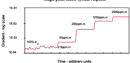
[image:5.612.306.518.541.644.2]The basic need for optically interrogated methane gas detection system did however stimulate further research and development resulting in the open path remote cell architectures described in outline above. The basic internal cell structure is shown in figure 8. It comprises two GRIN lens connected single mode fibres acting as source and collection lenses producing a parallel beam which acts over a path of typically 5cm. The basic performance characteristics of such a cell in terms of detection sensitivity for methane when interrogated at a wavelength of 1.67 microns are shown in figure 9. The
Figure 8: Schematic diagram of a single absorption cell
Block with V-groove GRIN lens
5.0 cm
Single mode optical fibre Block with V-groove GRIN lens
5.0 cm
Single mode optical fibre
Figure 9: Typical sensitivity levels for a single cell system responding to methane gas in air
1E-04 1E-03 1E-02 1E-01
G
radi
ent
-log
sca
le
2.5ppm.m 25ppm.m
250ppm.m
1250ppm.m 2500ppm.m
100%N
2
Single point sensor system response
Time - arbitrary units
1E-04 1E-03 1E-02 1E-01
G
radi
ent
-log
sca
le
2.5ppm.m 25ppm.m
250ppm.m
1250ppm.m 2500ppm.m
100%N
2
Single point sensor system response
Time - arbitrary units
1E-04 1E-03 1E-02 1E-01
G
radi
ent
-log
sca
le
2.5ppm.m 25ppm.m
250ppm.m
1250ppm.m 2500ppm.m
100%N
2
Single point sensor system response
noise level is a few ppm.m corresponding to detection thresholds of typically 50 ppm and a guaranteed detection threshold of 100 ppm or 0.01% by volume – well below the 5% lower explosive limit. Additionally the same concept - indeed the same cell and fibre interconnect structure will operate successfully up to 100% methane concentration for pressures around one bar(6). This dynamic range is unique among the many technologies which have evolved to address
the detection of methane.
Furthermore the detection limit on our cell design is imposed by the effect of spurious Fabry Perot resonances set up between the ends of the absorption cell with a free spectral range of about 3GHz which is very similar to the half width of the absorption line. Consequently since the detection thresholds are not limited by optical power availability in the single cell case then this optical power can be divided among many, many cells without compromising the sensitivity achievable at each one. Our power budget calculations point toward a capacity of over 200 and our practical experience extends to over 80.
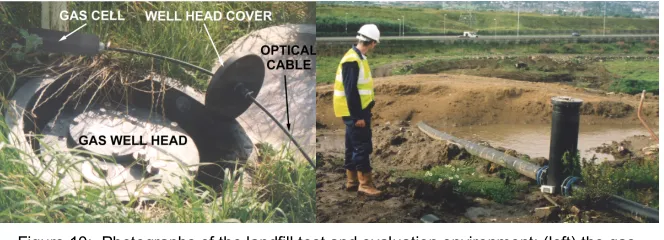
Our direct field experience has been predominantly operating within the hostile environment of an operational landfill site (figure 10). The methane gas generated through anaerobic decomposition of organic waste in many landfill sites worldwide is collected and burnt in gas engines to produce electricity. For example, the site shown in figures 10 generates in total ~8MW. A typical distribution of gas volume production from two sample wells is shown in figure 11 illustrating occasional abrupt fluctuations in the supply and in the values of gas concentrations in perimeter monitoring areas. We have observed
[image:6.612.138.470.243.363.2]continuous reliable unattended operation of these systems over periods of years during which the self calibrating and self referencing concepts mentioned earlier in this paper have been verified in practice. We have also tested systems in ventilation tunnels, again for methane, in fuel cells to monitor water vapour and in sterilization cabinets to determine the
Figure 10: Photographs of the landfill test and evaluation environment: (left) the gas collection wellhead and (right) the gas collection pipework prior to landscaping
Figure 11: Some sample outputs from a landfill site demonstrating unusual methane concentration fluctuations for (upper trace) an operational fuel
producing well and (lower trace) a perimeter monitoring well 0
10 20 30 40 50 60
4-Dec 6-Dec 8-Dec 10-Dec 12-Dec 14-Dec
Date
% Me
th
an
e
[image:6.612.79.546.462.603.2]Cell A12 Cell C8
Figure 12: Some practical absorption cell designs enabling cell and fibre interconnect to be ruggedly packaged together
Clip on replaceable sensor head Ceiling mounted fibre
optic junction box
For Tunnels and Mines
Clip on replaceable sensor head Ceiling mounted fibre
optic junction box
Clip on replaceable sensor head Ceiling mounted fibre
optic junction box
concentrations of vapour phase hydrogen peroxide during and after sterilization procedures. In all cases the inherent technical performance has been comparable to or better than competing technologies most notably electro chemical based systems. The overall system benefits have been maintained and the economic profile of the installed and operated sensor has been highly competitive. The sensor heads have been well engineered and packaged and a couple of typical examples are shown in figure 12 illustrating basic approaches used in landfill sites and tunnel ventilation. In both cases the sensor itself is encased in a package approximately 30 cms in length designed to be compatible with the operational environment.
SOME VARIATIONS ON THE THEME
The tuneable diode laser “engine” is at the heart of these systems. Whilst the modulation characteristics of the tuneable diode laser in response to current drive are perhaps a little eccentric, these eccentric characteristics can, as we have indicated, be accommodated into relatively straightforward and simplistic signal processing algorithms from which very accurate information can be derived. During recent years optical systems have evolved and enabled a wide variety of guided wave optical components compatible with fibre interconnects of which amplifiers and frequency shifting parametric oscillators are in our current context extremely interesting. The implication is that the basic diode laser engine can be exploited either at much higher power levels or even in different wavelength bands.
One such potential application of these concepts is shown in figure 13 which illustrates an open path system(7) which
detects methane between the source (the same tuneable diode laser engine amplified using Raman amplification provided through a pump furnished through an erbium doped fibre amplifier) and a diffuse reflective target some tens or hundreds of metres distant. The results of some preliminary field trials are shown in figure 14 illustrating that a methane cloud of 100 ppm over a range of 100 metres can be detected using light diffusely reflected from a remote target. Prospective applications include pipe line monitoring and the assessment of emissions from both brown field sites and landfill.
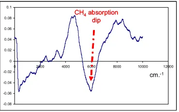
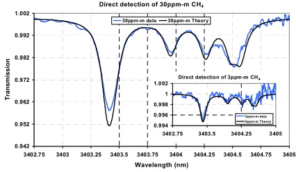
Another application – this time based on optical parametric interactions in periodically poled lithium niobate (PPLN) is shown in figure 15. The basic concept here is to shift the tuneable diode laser radiation from the near infrared to the mid infrared(8) where the intrinsic absorption line strength is a factor of a few hundred higher so consequently in principle
methane gas can be detected at much higher sensitivities. Figure 16 shows some of the results of some very preliminary experiments based on this concept and even in these preliminary experimental excursions we see sensitivities
demonstrably below the ppm.m level.
We have also exploited the TDLS regime in the context of photoacoustic spectroscopy based on both a direct wavelength sweep and also using an external intensity modulation at an acoustic frequency to produce the photoacoustically(9)
[image:7.612.350.535.367.483.2]detected line shapes which we find are again in a very good agreement with the calculated lineshapes. Much can
Figure 13: Open path backscatter based gas measurements using the TDLS ‘engine’ plus a Raman amplifier to boost the available
power.
High power O/P Ramp & Sine wave
modulation
Tuneable DFB
Laser core WDM
OFS Raman fibre
WDDM 1% Tap
i/p powers
1650nm
SBS
1540nm 5W EDFA
Broad EDFA seed arrangement
1650nm
1540nm
Output – via Fresnel lens to ~10cm diameter beam – far field ~ km!
TDLS engine
High power O/P Ramp & Sine wave
modulation
Tuneable DFB
Laser core WDM
OFS Raman fibre
WDDM 1% Tap
i/p powers
1650nm
SBS
1540nm 5W EDFA
Broad EDFA seed arrangement
1650nm
1540nm
Output – via Fresnel lens to ~10cm diameter beam – far field ~ km!
[image:7.612.82.332.369.470.2]TDLS engine
Figure 14: Field result - ‘rusty’ Metal diffuser plate at ~10m with 100ppm.m methane with <10mW launch power -0.08
-0.06 -0.04 -0.02 0 0.02 0.04 0.06 0.08 0.1
0 2000 4000 6000 8000 10000 12000
cm.-1
CH4absorption dip CH4absorption
potentially be gained by tuning the laser modulation frequency to acoustic resonances in the gas absorption cell. Ongoing work will refine the current techniques to both enhance the basic sensitivity and quantify threshold detection levels.
Finally there are a number of intellectually interesting intracavity architectures which we have explored in both lasing(10)
and spontaneous emission modes(11) from fibre lasers. These are of course restricted to detecting gases with convenient
absorption lines, of with acetylene has been the most frequently examined example. The results of these investigations have yet to be fully and conclusively evaluated in a technological context, most notably because parameters such as scale factor and threshold sensitivity are highly dependent on the cavity operating point with respect to threshold. This is usually difficult to accurately maintain and remains an issue with most, probably all, intracavity architectures.
CONCLUSIONS
Fibre optic linked tuneable diode laser spectroscopy offers a remarkably flexible tool for gas sensing. The basic principles have now been well established and enable sensitive and accurate measurements to be made for the concentrations of a variety of gases with absorption spectra in the near infrared. Applications of this can include ventilation systems, gas storage systems, pipe line monitoring and, as the undoubted social pressures increase, as a monitoring tool to quantify carbon based emissions and the related potentials for defining charges associated with carbon trading and taxation. This very brief overview serves to emphasise the immense potential which these techniques offer in current and, more important, future application sectors most notable in energy generation and storage, safety and security and environmental assessment.
ACKNOWLEDGEMENTS
[image:8.612.72.292.185.311.2]The work reported here is drawn from the contributions of a community of around 20 research students and postdoctoral fellows and has benefitted immeasurably from liaisons with numerous external industrial academic and government
Figure 15: Mid infra red generation from pump and probe
wavelength of 1.064 and 1.547 μm for methane at 3.403 μm
[image:8.612.318.531.188.312.2]TDLS engine TDLS engine TDLS engine
Figure 16: Results for 30ppm.m and 3ppm.m CH4concentrations
and equivalent HITRAN database calculations.
Direct detection of 30ppm-m CH4
0.942 0.952 0.962 0.972 0.982 0.992 1.002
3402.75 3403 3403.25 3403.5 3403.75 3404 3404.25 3404.5 3404.75 3405 Wavelength (nm)
Tr
a
n
sm
ission
30ppm-m data 30ppm-m Theory
Direct detection of 3ppm-m CH4
0.994 0.996 0.998 1 1.002
collaborators both in the UK and Europe. The work has been supported by the UK EPSRC, the European Union, and several industrial contract sponsors, especially those associated with our collaborative programmes.
BIBLIOGRAPHY
[1] Reid, J., Garside, B.K., Shewchun, J. et al., “High sensitivity point monitoring of atmospheric gases employing tunable diode lasers,” Applied Optics, vol. 17, no. 11, pp. 1806-1810, 1978.
[2] Culshaw, B., ‘Gas spectroscopy techniques for optical fibre sensors,’ in J-M Lopez-Higuera(ed), Handbook of optical fibre sensing technology, pp247-270, Wiley 2002.
[3] Duffin, K., Johnstone, W., McGettrick, A., Moodie, D., Stewart, G., Thursby, G. and Culshaw, B. "Chemical Sensor Networks for Gas Detection and Environmental Monitoring", Invited paper in Current Analytical Chemistry, Vol. 4, No. 4, pp391-402, October 2008.
[4] Johnstone, W., McGettrick, A. J., Duffin, K. et al., “Tunable Diode Laser Spectroscopy for Industrial Process
Applications: System Characterization in Conventional and New Approaches,” Sensors Journal, IEEE, vol. 8,
no. 7, pp. 1079-1088, 2008.
[5] Stewart, G., Jin W. and Culshaw, B. Prospects for fibre-optic evanescent-field sensors using absorption in the
near infra-red, Sensors and Actuators B, pp38-49, 1997, pp42-47.
[6] Culshaw, B., Stewart, G. and F. Dong, F. et al., “Fibre optic techniques for remote spectroscopic methane
detection--from concept to system realisation,” Sensors and Actuators B: Chemical, vol. 51, no. 1-3, pp. 25-37,
1998.
[7] Mitchell, D., Duffin, K. and Johnstone, W. ‘Remote methane sensor using Tunable Diode Laser Spectroscopy (TDLS) via a 1W Raman Source,’ Proc OFS(20) Edinburgh October 2009, SPIE Vol7503 -50.
[8] Armstrong, I., Johnstone, W., Duffin, K., Lengden, M., Chakraborty, A.L. and Ruxton, K. “Detection of CH4
in the Mid-IR using Difference Frequency Generation with Tunable Diode Laser Spectroscopy”, IEEE Journal of Lightwave Technology, Submitted February 2010.
[9] Li Li, Thursby, G., Stewart, G., Arsad, N., Uttamchandani, D., Culshaw, B. and Wang Y, ‘Recovery of acetylene absorption line profile basing on tuneable diode laser spectroscopy with intensity modulation and photoacoustic spectroscopy’, Proceedings Photonics Europe April 2010 SPE Proceedings Paper 7726-64.
[10] Stewart, G., Shields, P., Culshaw, B., Development of fibre laser systems for ring-down and intra-cavity gas
spectroscopy in the near-IR Measurement, Meas Sci Technol. Vol 15, 2004, pp1621-1628.
[11] Arsad, N. and Stewart G. ’Intra-cavity spectroscopy using amplified spontaneous emission in erbium fibre