University of Southern Queensland
Faculty of Engineering & Surveying
Research, Design and Develop a Pipe
Latching/Unlatching Device that can be used to help
Automate the Pipe Tripping Process
A dissertation submitted by
Steven Michael Sullivan
In fulfilment of the requirements of
ENG4112 Research Project Part 2
Towards the degree of
Bachelor of Engineering (Mechanical)
Abstract
The Oil and Gas Well Service industry is a highly competitive industry in Australia and around the world and there is a growing need to make advancements in the way of technology. One of the biggest technological advances that this industry could make would be to semi-automate the process of pulling and running tubing. This would have many benefits such as increased safety for rig personnel and decreased time needed to service a well.
The aim of this project was to research, design and develop a pipe latching/unlatching device that can be used to help automate the pulling and running of tubing process that is currently in use on rigs. To achieve this objective, analysis of existing designs on the market was conducted to gain an appreciation of pipe latching/unlatching devices and to evaluate their capability. There was not a lot of information to be found in this area but what was found assisted in conceptualising designs. The viability of the conceptual designs was investigated and a cost analysis of each design was conducted. The optimal design was chosen based on the requirements of Easternwell and the effectiveness and cost of each system. The details of the design, component selection and operation of the system were examined and preliminary finite element analysis (FEA) was carried out on the device. Recommendations for possible modifications were made by the author after consultation with professional engineers.
University of Southern Queensland
Faculty of Engineering and Surveying
ENG4111 Research Project Part 1 &
ENG4112 Research Project Part 2
Limitations of Use
The Council of the University of Southern Queensland, its Faculty of Engineering and Surveying, and the staff of the University of Southern Queensland, do not accept any responsibility for the truth, accuracy or completeness of material contained within or associated with this dissertation.
Persons using all or any part of this material do so at their own risk, and not at the risk of the Council of the University of Southern Queensland, its Faculty of Engineering and Surveying or the staff of the University of Southern Queensland.
This dissertation reports an educational exercise and has no purpose or validity beyond this exercise. The sole purpose of the course "Project and Dissertation" is to contribute to the overall education within the student’s chosen degree programme. This document, the associated hardware, software, drawings, and other material set out in the associated appendices should not be used for any other purpose: if they are so used, it is entirely at the risk of the user.
Professor Frank Bullen
Dean
Certification of Dissertation
I certify that the ideas, designs and experimental work, results, analyses and conclusions set out in this dissertation are entirely my own effort, except where otherwise indicated and acknowledged.
I further certify that the work is original and has not been previously submitted for assessment in any other course or institution, except where specifically stated.
Steven M. Sullivan Q11215856
________________________________ Signature ________________________________
Acknowledgments
Firstly I would like to thank the Easternwell Group for providing me with this project and allowing me the time and resources to complete it. I would also like to thank Guido Stangherlin (EWG), Stan Westcott (EWG) and John Shaw (Solidtech) for their technical support and advice and Dr Selvan Pather for his guidance and advice with the dissertation. Finally, thankyou to Pippa for your ongoing support, interest and encouragement throughout this project.
STEVEN MICHAEL SULLIVAN
Contents
Abstract i
Certification of Dissertation iii
Acknowledgments iv
List of Figures ix
List of Tables xi
Nomenclature xii
Chapter 1 – Introduction 1
1.1 Introduction 1
1.2 Project Sponsor 1
1.3 Problem Statement 2
1.4 Reasons for the Project 2
1.5 Objectives 3
1.5.1 System Outline 3
1.5.2 Project Aim 4
1.6 Methodology 4
1.7 Overview 5
1.8 Conclusion 6
Chapter 2 – Background 7
2.2 Well Servicing 7
2.2.1 Completion of New Wells 7
2.2.2 Service of Existing Wells 10
2.3 Service/Work-Over Rig 10
2.4 Developments in Pipe Handling Practices 12
2.4.1 Hydraulic Pipe Handler 13
2.5 Pulling and Running Tubing Using the HPH 15
2.6 Conclusion 18
Chapter 3 –Investigation into Existing Elevator Design 19
3.1 Introduction 19
3.2 Petol “Big D” Tubing Elevator 19
3.2.1 Description and Features 20
3.2.2 Operation 21
3.3 BX Hydraulically Actuated Elevator 21
3.3.1 Features and Benefits 22
3.4 Automated Side Door (ASD) Elevator 23
3.4.1 Features and Benefits 23
3.5 XP 1000 Extreme Performance Elevator 24
3.5.1 Features 25
3.5.2 Benefits 25
3.6 VES-SD Series Elevator 25
3.6.1 Features and Benefits 25
3.7 VES-CL Series Elevator 27
3.7.1 Features and Benefits 27
3.8 Conclusion 28
Chapter 4 – Conceptual Designs 29
4.2 Design Details 29
4.3 Concept Design 1 32
4.3.1 Operation 33
4.3.2 Cost Analysis Concept Design 1 33
4.3.3 Advantages of Concept Design 1 34
4.3.4 Disadvantages of Concept Design 1 34
4.4 Concept Design 2 36
4.4.1 Operation 37
4.4.2 Cost Analysis Concept Design 2 37
4.4.3 Advantages of Concept Design 2 37
4.4.4 Disadvantages of Concept Design 2 38
4.5 Concept Design 3 39
4.5.1 Operation 40
4.5.2 Cost Analysis Concept Design 3 40
4.5.3 Advantages of Concept Design 3 41
4.5.4 Disadvantages of Concept Design 3 42
4.6 Concept Design 4 43
4.6.1 Operation 44
4.6.2 Cost Analysis Concept Design 4 44
4.6.3 Advantages of Concept Design 4 44
4.6.4 Disadvantages of Concept Design 4 45
4.7 Design Recommendations and Selection 46
4.8 Conclusion 46
Chapter 5 – Final Design, Construction and Evaluation 47
5.1 Introduction 47
5.2 Prototype Design Details 47
5.2.1 Material Selection 47
5.2.2 Critical Dimensions of the Design 48
5.3.1 Calculations of the Applied Forces on the Device 50 5.3.2 Finite Element Analysis (FEA) of the Chosen Design 52
5.3.2.1 Main Body FEA 52
5.3.2.2 Base Assembly FEA 55
5.3.3 Evaluation of Design FEA Results 58
5.3.4 Hydraulic Cylinder Calculations 59
5.4 Cost Analysis 64
5.5 Conclusion 65
Chapter 6 – Conclusions and Further Work 66
6.1 Introduction 66
6.2 Summary of Objectives Achieved 66
6.3 Further Design Considerations 67
6.4 Future Development in Design 68
6.5 Conclusion 68
References 69
Appendix A – Project Specification 70
Appendix B – String Weight VS Clamping Moment Table 72
List of Figures
FIGURE 1:TYPICAL OIL WELL CONSTRUCTION... 8
FIGURE 2:EWGRIG 2 WITH BEAM PUMP... 9
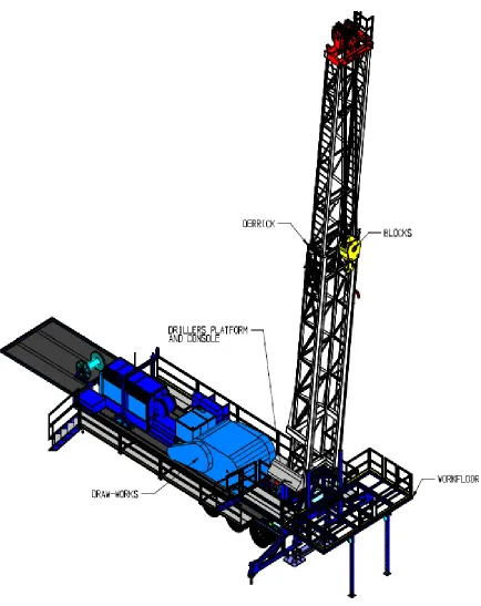
FIGURE 3:SERVICE RIG... 11
FIGURE 4:EWGRIG WITH PIPE STANDING IN DERRICK... 13
FIGURE 5:HPH PIPE RACKS AND RIG WORK-FLOOR... 14
FIGURE 6:HPH LOADED WITH PIPES... 14
FIGURE 7:FLOOR-HAND WAITING FOR PIPE... 16
FIGURE 8:FLOOR-HAND CHECKING THAT LATCH IS SECURED... 16
FIGURE 9:FLOOR-HAND WAITING FOR PIPE TO BE ELEVATED... 16
FIGURE 10:PIPE BEING ELEVATED... 16
FIGURE 11:FLOOR-HAND PUSHING PIPE ONTO HPH ... 17
FIGURE 12:PETOL “BIG D”TUBING ELEVATOR... 20
FIGURE 13:BXHYDRAULICALLY ACTUATED ELEVATOR... 23
FIGURE 14:ASDELEVATOR IN USE... 24
FIGURE 15:XP1000ELEVATOR... 24
FIGURE 16:VES-SDELEVATOR... 26
FIGURE 17:VES-CLELEVATOR... 27
FIGURE 18:VES-CLELEVATOR -CUT... 27
FIGURE 19:PICKING UP PIPE OFF HPH ... 30
FIGURE 20:CONCEPT DESIGN 1CLOSED... 32
FIGURE 21:CONCEPT DESIGN 1OPEN... 32
FIGURE 22:CONCEPT DESIGN 2CLOSED... 36
FIGURE 23:CONCEPT DESIGN 2OPEN... 36
FIGURE 24:CONCEPT DESIGN 3CLOSED... 39
FIGURE 25:CONCEPT DESIGN 3OPEN... 39
FIGURE 26:CONCEPT DESIGN 4CLOSED... 43
FIGURE 29:GRAPH OF STRING WEIGHT VERSUS THE CLAMPING MOMENT... 51
FIGURE 30:LOADS APPLIED TO MAIN BODY HALF... 53
FIGURE 31:10MM MESH APPLIED TO MAIN BODY HALF... 53
FIGURE 32:FEA OF MAIN BODY HALF SHOWING MAX.STRESS EQUALS 980.1MPA... 54
FIGURE 33:FEA OF MAIN BODY HALF SHOWING MAX DEFORMATION IN THE X-DIRECTION EQUALS 2.154MM... 54
FIGURE 34:LOADS APPLIED TO BASE ASSEMBLY... 55
FIGURE 35:10MM MESH APPLIED TO BASE ASSEMBLY... 55
FIGURE 36:FEA OF BASE ASSEMBLY SHOWING MAX.STRESS EQUALS 1228MPA... 56
FIGURE 37:FEA OF BASE ASSEMBLY SHOWING MAX DEFORMATION IN THE X-DIRECTION EQUALS 0.9673MM... 56
FIGURE 38:FEA OF BASE ASSEMBLY SHOWING MAX DEFORMATION IN THE Y-DIRECTION EQUALS 1.018MM... 57
FIGURE 39:FEA OF BASE ASSEMBLY SHOWING MAX DEFORMATION IN THE Z-DIRECTION EQUALS 0.472MM... 57
FIGURE 40:FINAL DESIGN WITH MODIFICATIONS... 58
FIGURE 41:RELEVANT DIMENSIONS FOR HYDRAULIC CYLINDER FORCE CALCULATION... 60
List of Tables
TABLE 1:COST ESTIMATE FOR CONCEPT DESIGN 1 ... 34
TABLE 2:COST ESTIMATE FOR CONCEPT DESIGN 2 ... 37
TABLE 3:COST ESTIMATE FOR CONCEPT DESIGN 3 ... 41
TABLE 4:COST ESTIMATE FOR CONCEPT DESIGN 4 ... 44
Nomenclature
Bails The bails are the joining links commonly used to connect the
blocks and the elevators.
Bails
Blocks The blocks are basically the hook that is connected to the main
winch via a set of cables. The size blocks that are normally used on service rigs range from 50T to 150T.
Casing This is the large diameter pipe that encloses a well. It is the outer most barrier to stop the well collapsing on itself. This casing is usually cemented into place. The tubing, rods and pumps are run inside of the casing.
Derrick The derrick is the mast structure on the Rig Carrier. They range in
capacities from 10 tonne to 500 tonne plus.
Derrick
Pulling Tubing Is the term used to describe the process of pulling the tubing out of a well.
Pulling and Running Pipe -1 Pulling and Running Pipe -2
Rods The rods are run inside the tubing and come in a range of different diameters and lengths. They are always a solid rod with a male thread on one end and an upset collar with a female thread on the other end. The rods are used to connect the pump in the bottom of the well to the driving mechanism on the surface.
Service Rig A service rig (also known as a work-over rig) is used for a number
EWG Service Rig #7 EWG Service Rig #8 Model
Slips This device sits at the top of the well and is used to clamp and hold
the pipe/tubing while the rig personnel are latching and elevating the next pipe to be run into the well.
Tubing Elevator This is a latching/unlatching device that is attached to the blocks on a rig and is used to grip and suspend tubing while pulling out or running in to a well.
Standard Tubing Elevator
Tubing The tubing is what the oil or gas flows upwards through, out of a
Chapter 1
Introduction
1.1
Introduction
The Oil and Gas Well Service industry is a highly competitive industry in Australia and around the world and there is a growing need to make advancements in the way of technology. One of the biggest technological advances that this industry could make would be to semi-automate the process of pulling and running tubing. This would have many benefits such as increased safety for rig personnel and decreased time needed to service a well. This project researches, designs and develops a pipe latching/unlatching device that can be used to help automate the pulling and running of tubing process that is currently in use on rigs. This chapter will introduce the aim, objective and reasons for the project. The methodology will be outlined and an overview of the project will also be included.
1.2
Project Sponsor
EWG has recently made advancements in pipe handling technology in the design construction and implementation of a Hydraulic Pipe Handler (HPH). The HPH ensures exact repetition of pipe position - this then opens the way for semi-automation of the pipe pulling and running process, the process of latching pipe, elevating it and lowering it in a controlled fashion. Current systems in use require manual input to control and latch the elevator, which is attached to a travelling block that is only controlled in the vertical axis. In order to automate the pulling and running process the blocks must be controlled in all axes and the pipe must be automatically latched and unlatched.
1.3
Problem Statement
The tubing elevators that are currently in use on service rigs require one or two people to catch the tubing and latch/unlatch the elevator. This is not only time consuming and costly but is also very dangerous work for the rig personnel. To stay ahead in a very competitive industry, EWG needs to semi-automate the process of pulling and running tubing. They have already started to make advances in this area with the design and development of the Hydraulic Pipe Handler. Designing and developing an automated pipe latching/unlatching device will be the next big advancement in achieving this goal.
1.4
Reasons for the Project
This project has come about due to a few factors. These are:
• An increase in safety for rig floor personnel. Rig personnel all over the world have been injured or killed in past decades from falling tubing caused by malfunctioning or incorrectly fastened elevators. Hand injuries are also very common for rig personnel who are handling the tubing elevators.
• A need to decrease the amount of time taken to service a well.
1.5
Objectives
The objectives and aim of the project were determined by the system outline provided by the Easternwell Group (EWG). The system outline and project aim are detailed below.
1.5.1 System Outline
• The latching mechanism is to be designed for use on a service/work-over rig that has its blocks constrained in all axes. The mechanism is also to be designed to work in conjunction with EWG’s Hydraulic Pipe Handler – this ensures exact repetition of pipe position.
• The mechanism should be able to be latched and unlatched without the need for any direct physical human contact. The mechanism may be hydraulically/pneumatically/electrically controlled from a point outside of the danger zone.
• The latching mechanism should be designed to allow for a range of different tubing diameters – from 1” to 2 7/8” tubing (pipe sizes are measured in imperial units). This will be decided by EWG.
• The latching mechanism can not be accidentally undone under ANY circumstances. This could result in dropping a complete string of tubing down a well – causing hundred’s of thousands of dollars worth of damage. An even worse outcome would be injuring or even possibly killing rig personnel.
• The mechanism should have a positive lock to avoid slippage of the tubing.
The system outline sets constraints for the project and from that the goals and aims of the project were set.
1.5.2 Project Aim
To research, design and develop a pipe latching/unlatching device that can be used to help automate the pulling and running of tubing process that is currently in use on rigs.
1.6
Methodology
To achieve the project objectives, the problem needs to be examined in a systematic manner. The stages of the project are outlined below.
• Conduct background research to find information relating to tubing latching/unlatching mechanisms and current methods of pulling and running tubing on existing service/work-over rigs.
• Undertake preliminary designs of some alternative methods of pipe latching/unlatching mechanisms.
• Once the most suitable design is chosen, design, develop and analyse the conceptual design.
Following the conceptual design developed in this project, EWG will undertake further work to:
• Manage the construction of the first prototype.
• Conduct in field testing and evaluate design.
• Suggest changes or additions to system based on conclusions from in field testing.
1.7
Overview
The project dissertation is compiled as follows:
Chapter 1: Introduction
The aim, objectives and reasons for undertaking the project, brief overview of the dissertation.
Chapter 2: Background
Background information on work-over rigs, oil and gas well servicing and production and existing methods running/tripping tubing.
Chapter 3: Investigation into Existing Designs of Elevators
An investigation into the existing designs of elevators in use.
Chapter 4: Conceptual Designs
Covers the design details, an analysis of the four concept designs, recommendations and selection of the final design and conclusions.
Chapter 5: Final Design, Construction and Evaluation
Summary of objectives achieved, further design considerations, current and future development in design and final concluding remarks.
1.8
Conclusion
Chapter 2
Background
2.1 Introduction
To gain a proper understanding of the benefits of and need for this project, some knowledge of the well servicing process and the equipment involved, will be provided. This chapter will explain the necessity of servicing new and existing oil and gas wells, the most common processes involved and the equipment used to do so.
2.2 Well Servicing
There are two main times when a well needs servicing. These are:
2.2.1 Completion of New Wells
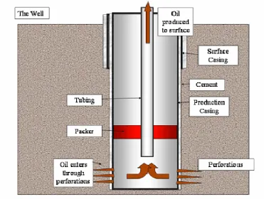
After drilling and casing a well, it must be 'completed'. Completion is the process in which the well is enabled to produce oil or gas. A common construction of an oil well is shown in Figure 1 below.
washouts and other problems, particularly from unconsolidated sand formations in offshore fields.
Figure 1: Typical Oil Well Construction
Image from http://en.wikipedia.org/wiki/Image:Oil_Well.png#file, Accessed 21/10/07
After a flow path is made, acids and fracturing fluids are pumped into the well to fracture, clean, or otherwise prepare and stimulate the reservoir rock to optimally produce hydrocarbons into the well-bore. Finally, the area above the reservoir section of the well is packed off inside the casing, and connected to the surface via a smaller diameter pipe called tubing. This arrangement provides a redundant barrier to leaks of hydrocarbons as well as allowing damaged sections to be replaced. Also, the smaller diameter of the tubing produces hydrocarbons at an increased velocity in order to overcome the hydrostatic effects of heavy fluids such as water.
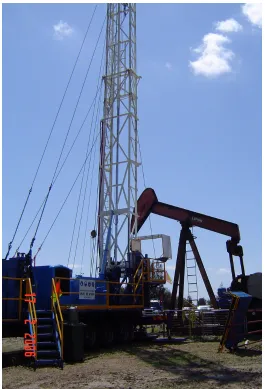
permeability oil reservoirs. Installing smaller diameter tubing may be enough to help the production, but artificial lift methods may also be needed. Common solutions include down-hole pumps (electric submersible pumps) or surface pump jacks (otherwise known as beam pumps) as can be seen in Figure 2 below.
2.2.2 Service of Existing Wells
Wells often need service or maintenance on surface or down-hole equipment. Well Servicing covers the maintenance, repair or stimulation of an existing well, carried out for the purpose of restoring, prolonging or enhancing oil and gas production. Working on an existing well to restore or increase oil and gas production is an important part of today’s petroleum industry, therefore, maintenance activities on existing oil and gas wells may include:
•Replacing the rods that connect the submersible pump to the driving mechanism on the surface.
•Replacing the tubing.
•Changing out the electric submersible pump.
•Removing the Horse-head off the Beam pump.
2.3 Service/Work-Over Rig
2.4 Developments in Pipe Handling Practices
One of the most labour intensive operations involved in well servicing is handling the rods and pipes/tubulars when running into a well or pulling out of a well. The most common methods of achieving this is listed below for when they are Running In or Pulling Out.
Running In:
•If the rods or pipe are light enough and the work-floor isn’t too high, rig personnel will manually lift the pipe or rods up to the work-floor from the racks that they are laid out on.
•If this is not the case, the rig personnel will run a cable from a small winch on the rig over the derrick and down to the level of their racks. They will then winch a number of rods or pipes at a time up to sit on the edge of the work-floor until they are needed.
Pulling Out:
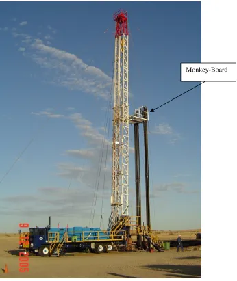
•If the rig is equipped with a ‘Monkey-board’ in the derrick as shown in the photos below, the pipe would be racked/stood in the derrick. This also means that one of the rig personnel (normally the Derrick-man) has to stand on the ‘Monkey-board’ in order to rack the pipe and release the elevators. This process is very dangerous as the Derrick-man is working at heights and the other rig personnel run the risk of falling pipe. This process is still widely used as it significantly speeds up the running in process after the service is completed.
Figure 4: EWG Rig with Pipe standing in derrick
2.4.1 Hydraulic Pipe Handler (HPH)
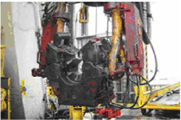
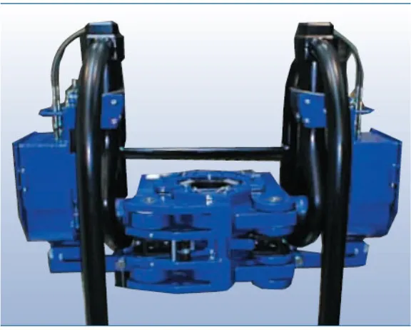
In order to make the above mentioned processes safer, faster and more efficient, Easternwell has recently made advancements in pipe handling technology in the design, construction and implementation of a Hydraulic Pipe Handler (HPH). There are two photos of the HPH shown in Figure 5 and Figure 6 below. There are many advantages to be gained in the use of the HPH. Some of these are given below:
•Allows for the removal of the ‘Monkey-board’ thus increasing safety because there is no longer a man working at heights or pipe standing in the derrick.
•The HPH ensures exact repetition of pipe position - this then opens the way for semi-automation of the pipe pulling and running process.
•The operator of the HPH sits in an air-conditioned cabin, therefore reducing the chance of fatigue induced accidents and heat stress.
•The use of the HPH speeds up the processes of running in and pulling out so the time to complete a service is less. This allows the rig to complete more work which means more income.
•The number of personnel can be reduced on a rig crew as the HPH makes the work less labor intensive. This also increases the profit margin.
Figure 5: HPH pipe racks and Rig Work-floor
2.5 Pulling and Running Tubing Using the HPH
The operation of Running Tubing into a well is as follows:
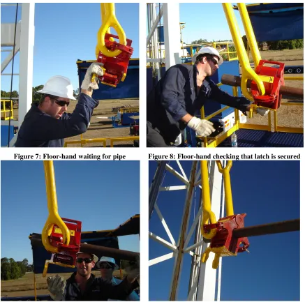
•The operator of the Hydraulic Pipe Handler would have a length of pipe/tubing loaded onto the trough of the HPH and raised to work floor height. The pipe would be positioned in the pre-set location, waiting to be latched.
•The Driller (the person operating the Rig from the operator’s console) lowers the blocks until the elevators are at a height where the Floor-hand can easily manoeuvre them onto the waiting pipe. See Figure 7.
•The Floor-hand will then close the elevator around the pipe and check to make sure that the latch has closed properly. See Figure 8.
•Once the Driller sees that the Floor-hand has finished he will increase throttle, release the brake and raise the blocks until the pipe swings to a vertical position above well centre. See Figure 9 and Figure 10.
•Once the pipe is vertical and has been elevated to the required height, it would be lowered and ‘stabbed’ into the threaded collar end of the previous pipe that is waiting in the slips. The Floor-hand will then use a hydraulic powered tong to screw the male threaded end of the elevated pipe into the female threaded end of the pipe that is held in the slips.
•Once the pipe is tightened to the required torque, the Driller will release the slips and lower the pipe until the elevators are just above the work floor. The slips will then be activated again and the elevators released.
Figure 7: Floor-hand waiting for pipe Figure 8: Floor-hand checking that latch is secured
Figure 9: Floor-hand waiting for pipe to be
elevated Figure 10: Pipe being elevated
The operation of Pulling Tubing out of a well is as follows:
•The Driller (the person operating the Rig from the operator’s console) lowers the blocks until the elevators are at a height where the Floor-hand can latch them onto the pipe that is protruding from the well.
•Once the Driller sees that the Floor-hand has finished he will release the slips, increase throttle, release the brake and raise the blocks until the joint between the first and second pipe is seen. The Driller will then engage the slips again and the Floor-hand will use a hydraulic power tong to unscrew the male threaded end of the elevated pipe out of the female threaded end of the pipe that is held in the slips.
•Once this is completed the Floor-hand will push the bottom end of the elevated pipe towards the back of the work floor as shown in Figure 11 below. The operator of the Hydraulic Pipe Handler would have the trough of the HPH raised to work floor height, so that as the Driller starts to lower the pipe, the Floor-hand can slide the end of the pipe onto the trough. The Driller lowers the blocks until the elevators are at a height where the Floor-hand can release them. The HPH operator will then lower the trough and eject the pipe onto the pipe racks.
[image:34.612.158.455.383.599.2]•The rig crew will then repeat this whole process until all of the pipes are out of the well and onto the pipe racks.
2.6 Conclusion
This chapter has covered the processes involved in well servicing or work-over and has also explained what a service/work-over rig is. Current practices and developments in pipe handling, including the HPH, have been discussed. This information has been found to be critical in helping to analyse the needs and requirements of the well servicing industry in order to design a useful product.
Chapter 3
Investigation into Existing Elevator Design
3.1 Introduction
The existing types of tubing elevators for service rigs are basically all the same bar some minor differences – mainly in the shape of the collar, door latch position and size. There are some semi-automated types of tubing elevators in use on service rigs today but they are normally a standard type elevator similar to the ‘Big D’ shown below that have been fitted with hydraulically or pneumatically operated cylinders. The elevators in use on the drilling rigs are much more advanced and most of these are semi-automated. The problem with these elevators though is that they are much too large for use on service rigs.
As the author could only find limited information on the existing designs of elevators in use on service rigs, information and specifications on the different styles of elevators in use on drilling rigs has also been added.
3.2
Petol “Big D” Tubing Elevator
Figure 12: Petol “Big D” Tubing Elevator GEARENCH (2005)
3.2.1 Description and Features
The BDA100 Petol Big D tubing elevator hangs from the elevator links which are attached to the traveling block of the service or drilling rig. The draw-works of the rig move the elevator up and down the rig’s derrick to install and remove tubing. The elevator may also be used on or around the rig floor for handling tubing.
Each elevator is bored for one size of tubing, 2-3/8 upset, 2-3/8 upset, 2-7/8 non-upset, 2-7/8 non-upset, 3-1/2 non-non-upset, or 3-1/2 upset. These are stamped 238N, 238U, 278N, 278U, 312N, or 312U respectively to indicate the appropriate size. The elevator has a rated capacity of 100 tons for heavy duty use.
The BDA100 offers the following features:
• A flame hardened top surface and special heat treated alloy materials to provide long life.
• Fully compliant with API specification 8C PSL level 1.
3.2.2 Operation
To attach the elevator to the tubing, the elevator operator stands on one side of the tubing which is supported in the slips with the elevator on the opposite side of the tubing. The operator reaches around the tubing with one hand on either side of the tubing. The elevator is gripped by the handles of the elevator. The operator pulls the opened elevator to the tubing and then brings the two handles together so that the elevator is wrapped around the tubing. This action causes the retainer and lock to automatically engage the locking lug on the right body half securing the elevator to the tubing. It is important for the elevator operator to visually verify that the retainer and lock properly engages the locking lug or premature release of the tubing could occur resulting in bodily injury and/or dropping the tubing down the well requiring fishing of the dropped tubing string. To remove the elevator from the tubing, the tubing is landed in the slips and the elevator in then lowered a few inches below the coupling. The elevator operator holds the handle on the right body half with one hand and uses the other hand to pull on the elevator lock. Pulling on the lock causes the lock to rotate free of the right body half releasing the retainer and fully opening the elevator in one smooth motion.
3.3
BX Hydraulically Actuated Elevator
3.3.1 Features and Benefits
•Purpose designed for hydraulic actuated operation
•Cost competitive with normal rig complement of air-operated, drill pipe, drill collar and casing elevators.
•The most economic way to fully actuate all elevator functions (opinion of Varco BJ).
•Double Door design for optimal balance and performance.
•The hydraulic cylinders are located the body casting for clean lines and maximum protection, and yet they are accessible for normal maintenance.
•Changeable bushings allow one elevator frame to handle all pipe size and type requirements.
•Bushings are locked into place with spring loaded pins for quick and easy removal and installation.
•Bushings can be changed within five minutes.
•No special tools are needed, no loose nuts, bolts or pins.
•Hinge journals are bushed to put major wear into replaceable components.
•One door bushing is spring loaded with a linkage connecting it to a locking pin. Any load on this bushing segment engages the pin preventing the elevator from opening. This safety lock prevents the elevator opening under load.
•The elevator is prepared for an interlock system as an option when used with a set of power slips.
•A trigger mechanism initiates the closing sequence when pipe is thrown into the elevator.
•Additionally equipped with a rotary actuator, it can be tilted to pick up pipe from the V-door, eliminating the need for single joint elevators.
Figure 13: BX Hydraulically Actuated Elevator Varco BJ (2002)
3.4
Automated Side Door (ASD) Elevator
The Automated Side Door Elevator, manufactured by Weatherford, was designed specifically to enhance safety and efficiency. Weatherford has had years of experience in Deepwater drilling were safety is paramount and every minute is critical to the operator.
3.4.1 Features and Benefits
• Double door and latch design provides 360 degree contact with the casing, allowing high tonnage without spreading the elevator body.
• Square shoulder design is compatible with numerous casing designs.
• Door and latch assembly are designed to carry the load of the casing joints picked up horizontally as illustrated.
• Hydraulic operation requires no human intervention to latch/unlatch.
• Fast cycle time means decreased run times.
Again, this style of elevator is only used on drilling rigs at the moment and is shown in Figure 14 below.
Figure 14: ASD Elevator in use www.weatherford.com (2007)
3.5
XP 1000 Extreme Performance Elevator
[image:41.612.216.392.517.678.2]The XP 1000 Elevator, manufactured by Access Oil Tools, is designed to support ultra high loads associated with critical deep water and deep well operations. This is another elevator that would be primarily used on a drilling rig and is shown in Figure 15 below.
3.5.1 Features
• Load rated at 1000 tonnes
• Uses hardened insert bushes
• Hydraulically Actuated
• Remote operation
• Compact, Versatile design
3.5.2 Benefits
• Provides safe and rapid installation
• Can be used with multiple pipe sizes and grades
• Minimizes injuries by removing personnel from the critical path area
• Can be used with 750 tonne or 1000 tonne links
3.6
VES-SD Series Elevator
This elevator, manufactured by Blohm+Voss Oil Tool Division, has the following features and benefits.
3.6.1 Features and Benefits
• Hydraulic operated Double Door Elevator System.
• Double Door design for optimal balance and performance.
• The most economical way to fully actuate all the elevator functions.
• Purpose design for actuated operation.
• The hydraulic system, including Cylinders, is located inside the body casting for clean lines and maximum protection, and for normal maintenance.
• Equipped with load sensor to avoid opening at the drillers console with a minimum load rate of 200 lbs.
• Integrated feed back advice.
• Emergency opening function.
• Integrated trigger system for automatically door closing.
• Hydraulic quick connections as standard.
• Suitable for B+V type elevator links 500 tonne rating.
• Hydraulic tilt actuator for ± 90° tilt operation to enable pickup from v-door.
• Hydraulic functions are speed adjustable.
• Mechanical stop pin holes at 5° intervals.
• Actuators swing out for quick and easy link removal.
[image:43.612.162.450.369.600.2]A photo of the VES-SD series elevator is shown in Figure 16 below.
3.7
VES-CL Series Elevators
[image:44.612.346.488.182.289.2]This elevator, manufactured by Blohm+Voss Oil Tool Division, has the following features and benefits and is shown in Figure 17 and Figure 18 below.
Figure 17: VES-CL Elevator
Figure 18: VES-CL Elevator - Cut www.blohmvoss-oiltools.com (2007) www.blohmvoss-oiltools.com (2007)
3.7.1 Features and Benefits
• World-wide, more than 250 VES-CL variable elevator systems are in operation.
• The VES-CL Elevator is the most flexible patented system in use for either manual or hydraulic operation.
• Available in load ratings of 150, 250, 350, 500 and 750 tons and manufactured to latest API-8C, PSL 1 standards.
• Each body is able to handle all pipe types and sizes by easily changeable bushings.
• Substantial savings, both in direct costs and logistics, are gained due to less maintenance, less spare parts, less freight and storage requirements.
• Depending on rig requirements, weight savings of up to 40% and initial investment cost savings of more than 20%, are possible.
• Suitable for Drill Collars, Casing and Tubing.
[image:44.612.124.271.184.291.2]3.8
Conclusion
This chapter has investigated the existing designs of elevators in use today. It was found that there is not a lot of information available on existing designs of elevators that are in use on service rigs. It was found however that the drilling industry is much more advanced in the way of automation and technology than the well servicing industry.
Chapter 4
Conceptual Designs
4.1 Introduction
This chapter follows on from the Investigation into Existing Elevator Design chapter and discusses the possible designs for the new latching/unlatching device. The basic design process for this project involved conducting research, gaining background information and reviewing the existing designs on the market. When knowledge of this area was gained, the author conceptualised designs and came up with a number of possibilities. The viability of these designs was investigated, details were discussed with suppliers and a brief cost analysis of each design was conducted. The optimal design was chosen based on the requirements of Easternwell, its effectiveness and cost of each design.
4.2 Design Details
As the device would be remotely operated, there are two issues that must be addressed. These are:
•Repetition of exact pipe position for pick-up and,
•Repetition of exact device position.
The first point has already been taken care of with the design and implementation of Easternwell’s Hydraulic Pipe Handler (HPH). Using the HPH the operator can position the pipe in the exact same position every time with ease.
[image:47.612.202.410.382.681.2]The second point would involve constraining the blocks in all axes. This could be achieved by retrofitting a set of rails and a guide to the rig derrick. To allow pick-up of pipe off the HPH the guide would also have to be fitted with a set of hoist cylinders in order to get the correct angle of pick-up. Figure 19 below illustrates why hoist cylinders would be required as part of the automation process. To pick up pipe that is sitting on the HPH, the device has to be lifted and angled correctly, which is a job normally performed by rig personnel.
There are other requirements that will determine the design of the device. These are:
•The size of the device will be partly determined by the size of attaching equipment, such as the bails and the pipes that it has to latch.
•The size and type of cylinders used will be as close to a manufactures standard range as possible in order to reduce lead times and cost.
•The hydraulic pressures that will be used when designing the cylinders will be dependant on the Service Rig’s hydraulic power capacity – standard is approximately 138 bar.
•Interference checking between connecting and moving parts will be carried out on the selected concept design with the aid of the 3D CAD model.
•The device will have to clamp onto itself and not the pipe, in order for the pipe to be able to be spun when connecting to the previous pipe. This means the inside diameter of the device should be slightly larger than the outside diameter of the pipe. The standard tubing/pipe that is used in oil and gas wells always have an upset collar on one end that is approximately 20mm larger in diameter than the pipe itself. The device should be latched directly below this collar, thus transferring the load through the top of the device when the weight of the pipe string is taken off the slips.
4.3 Concept Design 1
[image:49.612.89.502.310.680.2]This first design, as shown in Figure 20 and Figure 21, is quite simple. As with all of the concept designs, this device utilizes the principle of self-locking when it is lifted – the more weight that is being lifted, the larger the clamping force on the device. The main device consists of a main body which is split into halves and a base assembly on which the main body pivots. The main device is connected to a set of specialized bails via a clevis style connection. The specialized bails have a pivot in the centre and have a hydraulic cylinder affixed to each in order to get them to ‘open’. This ‘opening’ function is how the device is opened, closed and locked.
Figure 20: Concept Design 1 Closed Figure 21: Concept Design 1 Open
Clevis style connection
Hoist cylinders and guide rails
4.3.1 Operation
The operation of this device would be as follows when running tubing and in reverse when pulling tubing:
•The operator of the Hydraulic Pipe Handler would have a length of pipe/tubing loaded onto the trough of the HPH and raised to work floor height. The pipe would be positioned in the pre-set location, waiting to be latched.
•The Driller (the person operating the Rig from the operator’s console) would open the device (via a hydraulic valve which runs the two cylinders on the side of the bails), raise the device to the required angle (via the hoist cylinders) and lower the blocks until the base assembly is cradled over the pipe.
•The driller would then close the device and start raising the blocks.
•The hoist cylinders would be single-acting so that as the blocks are raised, the pipe gently swings to a vertical position without needing input from the driller.
•Once the pipe is vertical and has been elevated to the required height, it would be lowered and ‘stabbed’ into the threaded collar end of the previous pipe that is waiting in the slips. A rig worker will then use a hydraulic power tong to screw the male threaded end of the elevated pipe into the female threaded end of the pipe that is held in the slips.
•Once the pipe is tightened to a particular torque, the driller will release the slips and lower the pipe until the device is just above the work floor. The slips will then be activated again and the device released. The driller will then repeat this whole process until all of the pipes are down the well.
4.3.2 Cost Analysis Concept Design 1
pivot in the middle of the bails and in the clevis connection to the device. The pricing for components is in Table 1.
ITEM COST ($)
Hydraulic Cylinders x 2 500 Special Bails 15000 Main Body 2000 Base Assembly 1000 Miscellaneous Costs 2000
TOTAL $20500
Table 1: Cost Estimate for Concept Design 1
4.3.3 Advantages of Concept Design 1
The advantages of Concept Design 1 are as follows:
•Self-locking when lifted. This is because the pivot points for the halves of the main body are inside of the pick-up points; therefore this generates a clamping force when lifted.
•Relatively simple design.
•Robust design would be well suited to rig personnel and harsh environmental conditions.
4.3.4 Disadvantages of Concept Design 1
The disadvantages of Concept Design 1 are as follows:
•More expensive than other alternatives due to specialised bails and 2 cylinders.
•If the device was to receive a hit from the bottom (ie, by running the device down too low and hitting the slips) it would want to try and force the device open.
•Extra pivot points in the middle of the bails and in the connection to the main body provide points for seizing and would need regular maintenance to keep lubricated.
•Extra pivot points also provide more places to get fingers pinched – hand injuries being the most common type of injuries for rig personnel.
4.4 Concept Design 2
[image:53.612.93.499.324.688.2]The second design, as shown in Figure 22 and Figure 23, is very similar to the first, with the major difference being the way that the device is connected to the bails. With this design, a standard bail-type connection has been used to provide some tolerance for misalignment and uneven ground. As with all of the concept designs, this device utilizes the principle of self-locking when it is lifted. The main device consists of a main body which is split into halves and a base assembly on which the main body pivots. The main device is connected to a set of specialized bails that have a pivot in the centre and have a hydraulic cylinder affixed to each in order to get them to ‘open’. This ‘opening’ function is how the device is opened, closed and locked.
Figure 22: Concept Design 2 Closed Figure 23: Concept Design 2 Open
Hoist cylinders and guide rails
Specialised bails with 2 cylinders Standard
4.4.1 Operation
The operation of this device is similar to the operation of Concept Design 1.
4.4.2 Cost Analysis Concept Design 2
The cost of Concept design 2 is relatively high. This is also mainly due to the fact that a non-standard, specialised set of bails would have to be manufactured. This design has two hydraulic cylinders used to open and close the design which also adds to the cost. Miscellaneous costs are relatively high as there would be the cost of extra pins for the pivot in the middle of the bails. The pricing for components is in Table 2.
ITEM COST ($)
Hydraulic Cylinders x 2 500 Special Bails 13000 Main Body 2000 Base Assembly 1000 Miscellaneous Costs 1750
TOTAL $18250
Table 2: Cost Estimate for Concept Design 2
4.4.3 Advantages of Concept Design 2
The advantages of Concept Design 2 are as follows:
•Self-locking when lifted. This is because the pivot points for the halves of the main body are inside of the pick-up points; therefore this generates a clamping force when lifted.
•Relatively simple design.
•Standard bail-end connection to the main body of the device allows freedom and tolerance for misalignment and uneven ground.
•Standard bail-end connection to the main body of the device takes away two of the pinch points in Concept design 1.
4.4.4 Disadvantages of Concept Design 2
The disadvantages of Concept Design 2 are as follows:
•More expensive than other alternatives due to specialised bails and 2 cylinders.
•If the device was to receive a hit from the bottom (ie, by running the device down too low and hitting the slips) it would want to try and force the device open.
•Extra pivot points in the middle of the bails provide points for seizing and would need regular maintenance to keep lubricated.
•Extra pivot points also provide more places to get fingers pinched – hand injuries being the most common type of injuries for rig personnel.
4.5 Concept Design 3
The third design, as shown in Figure 24 and Figure 25, is quite different to the previous, with the major differences being the single standard hydraulic cylinder for opening, closing and locking and the fact that a standard set of bails may be used. As with all of the concept designs, this device utilizes the principle of self-locking when it is lifted. The main device consists of a main body which is split into halves and a base assembly on which the main body pivots. The lugs on the bails where the hoist cylinders attach would be of clamp-on style.
Figure 24: Concept Design 3 Closed Figure 25: Concept Design 3 Open
Hoist cylinders and guide rails Standard
bail type connection
Standard bails
[image:56.612.81.503.283.669.2]4.5.1 Operation
The operation of this device would be as follows when running tubing and in reverse when pulling tubing:
•The operator of the Hydraulic Pipe Handler would have a length of pipe/tubing loaded onto the trough of the HPH and raised to work floor height. The pipe would be positioned in the pre-set location, waiting to be latched.
•The Driller (the person operating the Rig from the operator’s console) would open the device (via a hydraulic valve which runs the hydraulic cylinder on the device), raise the device to the required angle (via the hoist cylinders) and lower the blocks until the base assembly is cradled over the pipe.
•The driller would then close the device and start raising the blocks.
•The hoist cylinders would be single-acting so that as the blocks are raised, the pipe gently swings to a vertical position without needing input from the driller.
•Once the pipe is vertical and has been elevated to the required height, it would be lowered and ‘stabbed’ into the threaded collar end of the previous pipe that is waiting in the slips. A rig worker will then use a hydraulic power tong to screw the male threaded end of the elevated pipe into the female threaded end of the pipe that is held in the slips.
•Once the pipe is tightened to a particular torque, the driller will release the slips and lower the pipe until the device is just above the work floor. The slips will then be activated again and the device released. The driller will then repeat this whole process until all of the pipes are down the well.
4.5.2 Cost Analysis Concept Design 3
(less hydraulic hose and fittings, ect) and no extra pins. The pricing for components is in Table 3.
ITEM COST ($)
Hydraulic Cylinder x 1 250 Standard Bails 10000 Main Body 2000 Base Assembly 1000 Miscellaneous Costs 1000
TOTAL $14250
Table 3: Cost Estimate for Concept Design 3
4.5.3 Advantages of Concept Design 3
The advantages of Concept Design 3 are as follows:
•Self-locking when lifted. This is because the pivot points for the halves of the main body are inside of the pick-up points; therefore this generates a clamping force when lifted.
•Relatively simple design.
•Robust design would be well suited to rig personnel and harsh environmental conditions.
•Standard bail-end connection to the main body of the device allows freedom and tolerance for misalignment and uneven ground.
•Using standard bails eliminates four of the pinch points previously mentioned.
•Considerably less expensive than the previous designs due to using a standard set of bails and only one hydraulic cylinder.
•By changing the method of opening and closing to just one cylinder, it has reduced the amount of vertical travel, thus reducing the chance of damaging pipe.
4.5.4 Disadvantages of Concept Design 3
The disadvantages of Concept Design 3 are as follows:
•If the device was to receive a hit from the bottom (ie, by running the device down too low and hitting the slips) it would want to try and force the device open.
4.6 Concept Design 4
[image:60.612.83.500.302.684.2]The fourth and final design, as shown in Figure 26 and Figure 27, is very similar to the previous, with the major differences being the non-standard, twin piston hydraulic cylinder which is used for opening, closing and locking and the slotted pick-up points. As with all of the concept designs, this device utilizes the principle of self-locking when it is lifted but this design is also self-locking when it is hit from the bottom. The main device consists of a main body which is split into halves and a base assembly on which the main body pivots. The lugs on the bails where the hoist cylinders attach would be of clamp-on style.
Figure 26: Concept Design 4 Closed Figure 27: Concept Design 4 Open
Standard bails
Hoist cylinders and guide rails Slotted
hole for bail connection
4.6.1 Operation
The operation of this device is similar to the operation of Concept Design 3.
4.6.2 Cost Analysis Concept Design 4
The cost of Concept design 4 is significantly less expensive than the first two concept designs but is slightly more expensive than concept design 3. This is due to the fact that a twin piston style hydraulic cylinder has been used. The pricing for components is in Table 4.
ITEM COST ($)
Hydraulic Cylinder x 1 350 Standard Bails 10000 Main Body 2000 Base Assembly 1000 Miscellaneous Costs 1000
[image:61.612.178.436.325.453.2]TOTAL $14350
Table 4: Cost Estimate for Concept Design 4
4.6.3 Advantages of Concept Design 4
The advantages of Concept Design 4 are as follows:
•Self-locking when lifted. This is because the pivot points for the two halves of the main body are inside of the pick-up points; therefore this generates a clamping force when lifted.
•Relatively simple design.
•Robust design would be well suited to rig personnel and harsh environmental conditions.
•Standard bail-end connection to the main body of the device allows freedom and tolerance for misalignment and uneven ground.
•Using standard bails eliminates four of the pinch points previously mentioned.
•Considerably less expensive than the first two designs due to using a standard set of bails and only one hydraulic cylinder.
•By changing the method of opening and closing to just one cylinder, it has reduced the amount of vertical travel, thus reducing the chance of damaging pipe.
•There are less obtrusive parts than the previous two designs that may become tangled in the derrick structure.
4.6.4 Disadvantages of Concept Design 4
The disadvantages of Concept Design 4 are as follows:
•Concept Design 4 is slightly more expensive than the previous because of the twin-piston hydraulic cylinder.
4.7 Design Recommendations and Selection
Selecting the final design involved presenting the main designs to Easternwell’s Engineering Manager and the other members of the Engineering team. The author recommended that Concept Design 4 be chosen as it covers the design criteria the best even though it is not the least expensive. The team at Easternwell agreed with this recommendation. The other feature that the Engineering Manager wanted to have included in the final design is the capacity to fit dies inside each half of the main body in order to be able to use the device on multiple pipe diameters. It was decided though, that for the first prototype this feature would not be important factor.
The most important design feature for Concept Design 4 was considered to be the slotted pick-up points in the main body as this would add an extra safety factor to the design. The fact that a standard set of bails may be used was also a major benefit as this would save time when retrofitting as well as a substantial amount of money.
4.8 Conclusion
Chapter 5
Final Design, Construction and Evaluation
5.1 Introduction
In the previous chapter Concept Design 4 was selected for development. This chapter follows on from that selection and covers the prototype design details and the selection and design of the critical components of the chosen design.
5.2 Prototype Design Details
This section will cover the material selection for the prototype design and also the critical dimensions. This section will also explain why the material and dimensions were chosen
5.2.1 Material Selection
The material that was chosen for the construction of the prototype was a 700MPa grade steel. After consulting with experts and carrying out Finite Element Analysis (FEA) on the chosen concept design, it was found that a material of this grade was required due to the high loading stresses that would be imposed on the device.
benefit of the device being easily welded is that it can be repaired rather than discarded if any cracking is picked up in routine Non-Destructive Testing (NDT), such as Magnetic Particle Testing. According to experts in this field (Carter, D. 2007, pers. comm.18 September), this is one of the biggest problems with the existing designs of elevators that are in use today.
5.2.2 Critical Dimensions of the Design
As shown in Figure 28, the overall width of the design is 740mm and the overall height is 429mm and the overall depth is 255mm. The whole device, including the hydraulic cylinder, will weigh approximately 120kg.
As mentioned in chapter 1, there where certain constraints that played a part in determining the critical dimensions of the prototype device. One of the most important factors is obviously the size of the pipe that it is going to latch. For the prototype it was decided to design the device to latch around 2 7/8” pipe, this being the most common size that is used by Service Rigs. Future prototypes will be designed to fit multiple pipe sizes but the first prototype will be used as a proof of concept only.
Figure 28: Chosen Prototype Design Dimensions
5.3 Selection and Design of Critical Components
This section will cover the selection and design of the critical components of the device, such as the loadings that will be applied to the device, FEA of the main body and base assembly and the calculation and sizing of the hydraulic cylinder. The components were designed and selected based on the following criteria:
•Availability
•Suitability
•Application
•Durability
5.3.1 Calculations of the Applied Forces on the Device
The most critical load that needs to be calculated is the maximum weight that the device will have to carry. After discussing the project with Easternwell management, it was decided to design the first prototype to carry a maximum load of 100 tonne. As the device is symmetrical about a central vertical axis, the calculations will be performed on one half of the main body. This means that 50 tonne or 50000kg will be the mass used for
calculations. This mass is subject to gravity, therefore the maximum force, FMax, that is
transmitted through each half of the device can be determined using the equation:
mg
FMax= (5.1)
where FMax = Maximum Force applied (N) m = Mass (kg)
g = Gravitational Acceleration (m/s2)
kN N
FMax=(50000×9.81)=490500 =490.5
Therefore, the Maximum Force that is applied through each half of the device is 490.5kN.
String Weight VS Clamping Moment 0 5000 10000 15000 20000 25000
0 10000 20000 30000 40000 50000 60000
String Weight (kg)
[image:68.612.101.471.113.333.2]C la m pi ng M om en t ( N .m )
Figure 29: Graph of String Weight versus the Clamping Moment
The Maximum Moment can be determined using the equation:
d F
MMax = Max (5.2)
where MMax = Maximum Moment applied (N.m) Max
F = Maximum Force applied (N)
d = The distance from the point where the force is applied (m)
m N MMax=(490500×0.041)=20110.5 .
5.3.2 Finite Element Analysis (FEA) of the Chosen Design
The FEA completed below on the main body half and base assembly was done as a first step in calculating whether the design is close to being strong enough. Due to time and budgetary constraints, this project will only include this preliminary FEA and an evaluation of the results with possible improvements shown. The first prototype will be constructed with the recommended possible improvements and load test as a proof of concept only.
The FEA that was carried out on the main body and base assembly was done using SolidWorks Office Premium 2007 and Cosmos, which is an FEA package that can be integrated into SolidWorks.
5.3.2.1 Main Body FEA
Figure 30: Loads applied to Main Body half
After consultation with FEA experts it was decided to apply a 10mm mesh to the main body half. A finer mesh may be used when further FEA is carried out. The applied mesh can be seen in Figure 31.
Figure 31: 10mm Mesh applied to Main Body half
Clamping Face
[image:70.612.128.483.429.673.2]As can be seen in Figure 32 below, the FEA produced a maximum stress of 980.1MPa while using a Deformation Scale of 20. The highest stresses were at the top of the pick-up point as would be reasonably expected.
Figure 32: FEA of Main Body half showing Max. Stress equals 980.1MPa
The next result of the FEA is the deformation in the x-direction as shown in Figure 33. Results show that the Maximum Deformation is 2.154mm using a deformation scale of 20.
[image:71.612.136.461.465.678.2]5.3.2.2 Base Assembly FEA
[image:72.612.128.487.477.679.2]The base assembly had loads applied as shown in Figure 34. A 500,000N bearing load was applied through each of the two holes in the base assembly which is where the main body pivots. The base assembly was restrained with inertial relief.
Figure 34: Loads applied to Base Assembly
After consultation with FEA experts it was decided to apply a 10mm mesh to the base assembly. A finer mesh may be used when further FEA is carried out. The applied mesh can be seen in Figure 35.
As can be seen in Figure 36 below, the FEA produced a maximum stress of 1228MPa while using a Deformation Scale of 20. The highest stresses were at the centre of the base assembly as would be reasonably expected.
Figure 36: FEA of Base Assembly showing Max. Stress equals 1228MPa
[image:73.612.95.520.151.367.2]The next result of the FEA is the deformation in the x-direction as shown in Figure 37. Results show that the Maximum Deformation is 0.9673mm using a deformation scale of 20.
The next result of the FEA is the deformation in the y-direction as shown in Figure 38. Results show that the Maximum Deformation is 1.018mm using a deformation scale of 20.
Figure 38: FEA of Base Assembly showing max deformation in the y-direction equals 1.018mm
[image:74.612.102.511.153.359.2]The final result of the FEA is the deformation in the z-direction as shown in Figure 39. Results show that the Maximum Deformation is 0.472mm using a deformation scale of 20.
5.3.3 Evaluation of Design FEA Results
[image:75.612.134.495.283.652.2]As seen from the FEA results in the previous section there were areas in the main body and base assembly that were too highly stressed. The main two sections that were too highly loaded were the top of the pick-up points at 980.1MPa and the centre of the base assembly at 1228MPa. It is common practice with Easternwell’s engineering team to design a part so that the stresses in it are no larger than 0.6 of the Yield Stress or in this case, 420MPa. After consultation with expert engineers, the changes shown below in Figure 40 were made to the design.
It is the opinion of an expert engineer (Stangherlin, G. 2007, pers. comm. 22 October) that by adding a top flange of about 12mm in thickness to the device, it would reduce the stresses in the main body to be close to 420MPa. It is also their opinion that if the gussets on the back of the base assembly were approximately 10 to 12mm thick they would also reduce the stresses in the base assembly to be close to 420MPa. This will of course be confirmed with further FEA as well as load testing on a prototype model. The first prototype will not be used in field on a Service Rig but in a controlled testing environment to prove that the concept of this device works.
5.3.4 Hydraulic Cylinder Calculations
The twin piston hydraulic cylinder that is to be used on the device will have a number of purposes. These are:
•Opening the device.
•Closing aid for the device.
•Acting as a “back-up” lock for the device.
Out of these three purposes for having the cylinder, opening the device will require the most force as the device is designed to be self-closing and self-locking when lifted.
Figure 41: Relevant dimensions for hydraulic cylinder force calculation
With this information the force created by the weight of the main body half, FWeight, can
be found using equation:
mg
FWeight = (5.3)
where FWeight = Force created by the weight of the part (N) m = Mass (kg)
g = Gravitational Acceleration (m/s2)
N
FWeight =(45×9.81)=441.45
The force, FCyl, needed by the cylinder to open one side of the device can now be found using equation: 0 ) ( ) (
0= × − × =
ΣM FCyl dc FWeight dw (5.4)
where ΣM0 = Sum of the Moments about the Pivot Point (N.m)
Cyl
F = Force needed to open one side of the device (N)
c
d = Distance from the Pivot Point to the Cylinder pin (mm)
Weight
F = Force from the self-weight of the main body half (N)
w
d = Distance from the Pivot Point to the COG (mm)
0 ) 135 45 . 441 ( ) 56 (
0= × − × =
ΣM FCyl
0 ) 75 . 59595 ( ) 56
(FCyl× − =
) 56 75 . 59595 ( = Cyl F N FCyl=1064.21
∴
kg FCyl=108.5
∴
Therefore the force that the hydraulic cylinder would be required to push is 1064.21N or the equivalent of 108.5kg. This is not much at all for a hydraulic cylinder.
Before any calculations were done to calculate the size of cylinder needed to push 1064.21N, the author firstly looked at a reputable hydraulic cylinder manufacturer’s specification sheets in order to try and use a standard cylinder. It was found that the smallest standard cylinder has a 38.1mm bore and a 19.1mm shaft, with an extend force capacity of 1607kg at 136 Bar. This information page can be found in Appendix C. While this cylinder is much higher rated than needed, it will work out less expensive to stay with a standard cylinder bore and shaft size.
•300mm closed length
•372mm open length
•Stroke of 36mm per piston
A diagram of one possible design for this cylinder is shown in Figure 42.
Figure 42: Twin Piston Hydraulic Cylinder for latching device
Using this information and the information gained from the cylinder manufacturer, some calculations can be performed in order to make sure that the cylinder will not fail. The author has