University of Southern Queensland
Faculty of Engineering & Surveying
‘Online Learning Environment’ using ASP.NET
A dissertation submitted by
Timothy Ross Vriesema
in fulfilment of the requirements of
ENG4111/2 Research Project
towards the degree of
Bachelor of Engineering (Software Engineering)
Bachelor of Business (Management and Leadership)
Abstract
This dissertation focuses on the management, design, implementation, testing, and
de-ployment of a learning environment for educational institutions. The management
ac-tivities of this project are based on the techniques outlined by Bruegge & Dutoit (2004)
and Sommerville (2001), involving the scheduling of project tasks, management of the
possible risks, and documentation of the project’s design. The design of the project
involves the integration and alteration of documents generated from the management
activities, while implementation consists of using the Microsoft .NET Framework class
library via the programming languages, ASP.NET, C# .NET, ADO.NET, XML, and
SQL. The activities revolving around testing focuses on its documentation via the
man-agement activities. As well, a small-scale deployment of this project is introduced into
University of Southern Queensland Faculty of Engineering and Surveying
ENG4111/2 Research Project
Limitations of Use
The Council of the University of Southern Queensland, its Faculty of Engineering and
Surveying, and the staff of the University of Southern Queensland, do not accept any
responsibility for the truth, accuracy or completeness of material contained within or
associated with this dissertation.
Persons using all or any part of this material do so at their own risk, and not at the
risk of the Council of the University of Southern Queensland, its Faculty of Engineering
and Surveying or the staff of the University of Southern Queensland.
This dissertation reports an educational exercise and has no purpose or validity beyond
this exercise. The sole purpose of the course pair entitled “Research Project” is to
contribute to the overall education within the student’s chosen degree program. This
document, the associated hardware, software, drawings, and other material set out in
the associated appendices should not be used for any other purpose: if they are so used,
it is entirely at the risk of the user.
Prof G Baker
Dean
Certification of Dissertation
I certify that the ideas, designs and experimental work, results, analyses and
conclu-sions set out in this dissertation are entirely my own effort, except where otherwise
indicated and acknowledged.
I further certify that the work is original and has not been previously submitted for
assessment in any other course or institution, except where specifically stated.
Timothy Ross Vriesema
Student Number: 0011122446
Signature
Acknowledgments
I would like to take this opportunity to thank the many people that influenced and
encouraged me throughout this project.
Firstly, I would like to thank my loving girlfriend, Cherie, and all the support she has
given me to continue the rigorous work required to complete this project. Her undivided
attention to my incessant ramblings on the technical development helped me overcome
problematic issues.
Secondly, I would like to thank my family for their ongoing support in my University
studies.
Thirdly, my supervisor, Dr. Hong Zhou. I would like to thank her for her constant
advice, feedback, and experience in our weekly meetings to allow my ideas to flow and
not kept inside my head.
Finally, in the research and implementation of this project, I was faced with many
programming language issues where I could not find the answers. The Most Valuable
Professional (MVP) developers within the Microsoft newsgroups promptly answered
my many of my questions. Thank-you to Jon Skeet [C# MVP], David Portas [SQL
Server MVP], and Oleg Tkachenko [XML MVP].
Timothy Ross Vriesema
Contents
Abstract i
Certification of Dissertation iii
Acknowledgments iv
List of Figures x
List of Tables xii
List of Listings xix
Chapter 1 Introduction 1
1.1 Structure of the Dissertation . . . 2
Chapter 2 Methodology and Techniques 3
2.1 Software Project Development . . . 4
2.2 Software Project Management . . . 5
CONTENTS vi
2.2.2 Software Project Documentation . . . 8
2.2.3 Software Project Schedule Management . . . 13
2.2.4 Software Project Risk Management . . . 14
2.3 Programming Languages . . . 14
2.3.1 Microsoft Active Server Pages .NET 1.1 . . . 17
2.3.2 Microsoft C# .NET 1.1 . . . 18
2.3.3 Microsoft Active Data Objects .NET 1.1 . . . 21
2.3.4 Extensible Markup Language . . . 21
2.3.5 Structured Query Language . . . 22
2.3.6 Hyper-Text Markup Language . . . 24
2.3.7 Cascade Style Sheeting . . . 24
2.4 Development Environments and Tools . . . 24
2.4.1 Microsoft Visual Studio .NET 2003 . . . 24
2.4.2 Microsoft ASP.NET Web Matrix . . . 25
2.4.3 Microsoft Windows Server 2003 . . . 25
2.4.4 Microsoft Internet Information Service 6.0 . . . 25
2.4.5 Microsoft SQL Server 2000 and 2005 . . . 26
2.4.6 Microsoft Developer Network . . . 26
2.5 Software Project Implementations . . . 27
CONTENTS vii
Chapter 3 Software Design 31
3.1 System Architecture . . . 31
3.1.1 System-to-Data Relationship . . . 33
3.1.2 Data Storage Techniques . . . 33
3.2 Database Architecture . . . 35
3.3 Design using the Microsoft .NET Framework . . . 46
Chapter 4 Software Implementation 50 4.1 Implementation Issues . . . 51
4.1.1 XML in Microsoft SQL Server 2000 . . . 51
4.1.2 Registry and File System Permissions . . . 51
4.1.3 Native XML Architecture . . . 52
4.2 Implementation using ASP.NET . . . 52
4.2.1 Authentication . . . 52
4.2.2 Web Forms and User Controls . . . 54
4.3 Implementation using XML . . . 54
4.3.1 XML Data Structures and Database Compatibility . . . 55
4.3.2 Serialization and Deserialization . . . 55
4.4 The Incomplete Web Application . . . 55
CONTENTS viii
5.1 Configuration of Microsoft Windows Server 2003 . . . 58
5.2 Installation - The Setup Application . . . 59
Chapter 6 Software Project Management 66 6.1 Documentation . . . 66
6.2 Schedule Management . . . 67
6.3 Risk Management . . . 69
6.4 Resource Requirements . . . 72
6.5 Implementation Management using Microsoft Visual Studio .NET . . . 73
6.5.1 Database Source Code Project . . . 75
6.5.2 OLEWebSetup Project . . . 77
Chapter 7 Conclusions 79 7.1 Further Work . . . 80
7.2 The Future Project . . . 81
References 83
Appendix A Project Specification 88
Appendix B Requirements Analysis Document 90
Appendix C System Design Document 122
CONTENTS ix
Appendix E Test Manual 166
Appendix F Web Application Model 186
Appendix G Project Gannt Chart 188
Appendix H Source Code 195
H.1 OLEWebApplicationProject . . . 195
H.2 OLEBusinessLogic Project . . . 293
List of Figures
2.1 The Waterfall Process Model . . . 7
2.2 The Evolutionary Development Process Model . . . 8
2.3 The outline of the Requirements Analysis Document (RAD) . . . 10
2.4 The outline of the System Design Document (SDD) . . . 11
2.5 The outline of the Object Design Document (ODD) . . . 12
2.6 The outline of the Test Manual . . . 13
2.7 The Microsoft .NET Framework’s components . . . 16
2.8 The tier application architectural designs . . . 29
3.1 The three-tier application architecture . . . 32
3.2 The steps in the Database Design Methodology (Steps 1 to 2) . . . 36
4.1 Login page . . . 56
4.2 Home page for user ‘Jonathan Trinder’ (userID: 26) . . . 56
LIST OF FIGURES xi
5.1 The Application Server window from the Windows Component Wizard,
underWindows Server 2003 . . . 59
5.2 Welcome screen (first step) . . . 60
5.3 SQL Server name setup (second step) . . . 61
5.4 IIS virtual folder and port setup (third step) . . . 62
5.5 Confirm installation (forth step) . . . 63
5.6 Setup installing (fifth step) . . . 64
5.7 Setup finished (sixth step) . . . 65
6.1 Microsoft Visual Studio .NET 2003’s Solution Explorer (for the OLE solution) . . . 74
6.2 Microsoft Visual Studio .NET 2003’sDebug Configuration Manager (for the OLE solution) . . . 75
6.3 Microsoft Visual Studio .NET 2003’sReleaseConfiguration Manager (for the OLE solution) . . . 75
6.4 Microsoft Visual Studio .NET 2003’s database table creation/alteration (for the OLEsolution) . . . 76
6.5 Microsoft Visual Studio .NET 2003’s database relationship creation/al-teration (for the OLEsolution) . . . 77
6.6 The User Interface configuration . . . 78
6.7 The File System configuration . . . 78
6.8 The Registry configuration . . . 78
List of Tables
2.1 Software processes within theIEEE 1074: Software Developing Life
Cy-cle Processes . . . 6
3.1 The attributes within the entity types Users, AETQuestions, and
AE-TAnswers . . . 38
3.2 The attributes within the entity types Classes, Roles, and
ThreadSub-scriptions . . . 38
3.3 The attributes within the entity typesClassUsers and OtherUsers . . . 39
3.4 The attribute domains for the attributes in Table 3.1 . . . 40
3.5 The attribute domains for the attributes in Table 3.2 . . . 40
3.6 The attribute domains for the attributes in Table 3.3 . . . 41
3.7 The highlighted and created primary and composite keys from Table 3.1 42
3.8 The highlighted and created primary and composite keys from Table 3.2 42
3.9 The highlighted and created primary and composite keys from Table 3.3 42
6.1 The Documentation, Requirements Elicitation and Analysis, and Design
LIST OF TABLES xiii
6.2 The Training, Implementation, Testing, and Deployment work structure 69
6.3 Risk types and the risks that may be encountered (Risk Identification) . 70
6.4 Risks, their probability and effects (Risk Analysis) . . . 71
6.5 Risks and their strategies (Risk Strategy) . . . 72
List of Listings
2.1 Interface example in C# . . . 19
2.2 C/C++ example of how and where memory is allocated and deallocated 20 2.3 C# example of where memory is allocated and deallocated . . . 20
2.4 FOR XML EXPLICIT stored procedure . . . 23
2.5 Output from the stored procedure in Listing 2.4 . . . 23
H.1 Class.aspx . . . 195
H.2 Class.aspx.cs . . . 196
H.3 Configuration.aspx . . . 200
H.4 Configuration.aspx.cs . . . 201
H.5 Default.aspx . . . 202
H.6 Default.aspx.cs . . . 204
H.7 Default.css . . . 204
H.8 Footer.ascx . . . 214
LIST OF LISTINGS xv
H.10 Global.asax . . . 214
H.11 Global.asax.cs . . . 214
H.12 Header.ascx . . . 218
H.13 Header.ascx.cs . . . 219
H.14 Login.aspx . . . 221
H.15 Login.aspx.cs . . . 222
H.16 Management.aspx . . . 222
H.17 Management.aspx.cs . . . 223
H.18 Menu.ascx . . . 224
H.19 Menu.ascx.cs . . . 225
H.20 Submission.aspx . . . 226
H.21 Submission.aspx.cs . . . 227
H.22 Web.config . . . 228
H.23 ClassControls/AETSubmissionList.ascx . . . 228
H.24 ClassControls/AETSubmissionList.ascx.cs . . . 228
H.25 ClassControls/ClassAnnoucements.ascx . . . 229
H.26 ClassControls/ClassAnnoucements.ascx.cs . . . 232
H.27 ClassControls/InformationAET.ascx . . . 233
H.28 ClassControls/InformationAET.ascx.cs . . . 234
LIST OF LISTINGS xvi
H.30 ClassControls/MultipleChoiceAET.ascx.cs . . . 237
H.31 ClassControls/ShortResponseAET.ascx . . . 242
H.32 ClassControls/ShortResponseAET.ascx.cs . . . 243
H.33 ClassControls/ShortResponseAETAnswers.ascx . . . 247
H.34 ClassControls/ShortResponseAETAnswers.ascx.cs . . . 247
H.35 ClassControls/ThreadPosts.ascx . . . 248
H.36 ClassControls/ThreadPosts.ascx.cs . . . 250
H.37 ClassControls/Threads.ascx . . . 252
H.38 ClassControls/Threads.ascx.cs . . . 253
H.39 ConfigurationControls/ApplicationConfiguration.ascx . . . 254
H.40 ConfigurationControls/ApplicationConfiguration.ascx.cs . . . 254
H.41 ConfigurationControls/ClassConfiguration.ascx . . . 255
H.42 ConfigurationControls/ClassConfiguration.ascx.cs . . . 255
H.43 ConfigurationControls/ClassEnrollmentConfiguration.ascx . . . 256
H.44 ConfigurationControls/ClassEnrollmentConfiguration.ascx.cs . . . 256
H.45 ConfigurationControls/InstitutionConfiguration.ascx . . . 256
H.46 ConfigurationControls/InstitutionConfiguration.ascx.cs . . . 257
H.47 ConfigurationControls/RoleAssignmentConfiguration.ascx . . . 257
H.48 ConfigurationControls/RoleAssignmentConfiguration.ascx.cs . . . 257
LIST OF LISTINGS xvii
H.50 ConfigurationControls/UserConfiguration.ascx.cs . . . 258
H.51 HomeControls/ErrorMessages.ascx . . . 259
H.52 HomeControls/ErrorMessages.ascx.cs . . . 261
H.53 HomeControls/ForumThreadSubscriptions.ascx . . . 262
H.54 HomeControls/ForumThreadSubscriptions.ascx.cs . . . 262
H.55 HomeControls/InstitutionAnnouncements.ascx . . . 263
H.56 HomeControls/InstitutionAnnouncements.ascx.cs . . . 266
H.57 HomeControls/QuickLinks.ascx . . . 267
H.58 HomeControls/QuickLinks.ascx.cs . . . 268
H.59 HomeControls/UpcomingDates.ascx . . . 269
H.60 HomeControls/UpcomingDates.ascx.cs . . . 271
H.61 LoginControls/Authentication.ascx . . . 273
H.62 LoginControls/Authentication.ascx.cs . . . 274
H.63 ManagementControls/ClassAnnouncementManagement.ascx . . . 275
H.64 ManagementControls/ClassAnnouncementManagement.ascx.cs . . . . 276
H.65 ManagementControls/ClassManagement.ascx . . . 276
H.66 ManagementControls/ClassManagement.ascx.cs . . . 277
H.67 ManagementControls/ClassNoteManagement.ascx . . . 277
H.68 ManagementControls/ClassNoteManagement.ascx.cs . . . 277
LIST OF LISTINGS xviii
H.70 ManagementControls/InformationAETManagement.ascx.cs . . . 278
H.71 ManagementControls/InstitutionAnnouncementManagement.ascx . . 279
H.72 ManagementControls/InstitutionAnnouncementManagement.ascx.cs 279 H.73 ManagementControls/MultipleChoiceAETManagement.ascx . . . 280
H.74 ManagementControls/MultipleChoiceAETManagement.ascx.cs . . . . 280
H.75 ManagementControls/ShortResponseAETManagement.ascx . . . 281
H.76 ManagementControls/ShortResponseAETManagement.ascx.cs . . . . 281
H.77 ManagementControls/UserManagement.ascx . . . 281
H.78 ManagementControls/UserManagement.ascx.cs . . . 282
H.79 MenuControls/Assignments.ascx . . . 282
H.80 MenuControls/Assignments.ascx.cs . . . 283
H.81 MenuControls/Classes.ascx . . . 284
H.82 MenuControls/Classes.ascx.cs . . . 285
H.83 MenuControls/Exams.ascx . . . 286
H.84 MenuControls/Exams.ascx.cs . . . 286
H.85 MenuControls/Notes.ascx . . . 288
H.86 MenuControls/Notes.ascx.cs . . . 288
H.87 MenuControls/Tutorials.ascx . . . 289
H.88 MenuControls/Tutorials.ascx.cs . . . 290
LIST OF LISTINGS xix
H.90 SubmissionControls/Class.ascx.cs . . . 291
H.91 SubmissionControls/User.ascx . . . 292
H.92 SubmissionControls/User.ascx.cs . . . 292
H.93 Address.cs . . . 293
H.94 AETAnswer.cs . . . 294
H.95 AETQuestion.cs . . . 309
H.96 Authentication.cs . . . 330
H.97 Class.cs . . . 332
H.98 Configuration.cs . . . 338
H.99 DataBridge.cs . . . 342
H.100 ErrorAndSecurity.cs . . . 358
H.101 Limitations.cs . . . 366
H.102 MD5Encryption.cs . . . 367
H.103 Post.cs . . . 368
H.104 Role.cs . . . 382
H.105 Thread.cs . . . 387
H.106 User.cs . . . 392
Chapter 1
Introduction
The idea of the‘Online Learning Environment’ using ASP.NET (OLE) was spawned
from an interest in software engineering. Software engineering is quite a broad area, so
the idea was to involve as many software engineering tasks as possible. These include
software project management and enterprise-level application architectural design,
im-plementation, testing, and deployment.
The initial ideas and research required a small amount of experience in application
design and implementation. Throughout the writer’s own technical experience and
University studies, experience within Microsoft Active Server Pages (ASP), C and C++,
and databases (SQL) in design, implementation, testing, and deployment had already
been achieved. For the purposes of this project however, the writer sought to expand
his current level of experience in these fields, to new, modern, and exciting fields.
The main inspiration for this project came from using an already established
enterprise-level Web application from the company WebCT, Inc. and their educational
1.1 Structure of the Dissertation 2
1.1
Structure of the Dissertation
The dissertation begins with Chapter 2, introducing methodologies and techniques
researched in order to gain an idea as to how development of the project would take
place. Chapter 6 then outlines the activities involved in software project management.
The design of the OLE project is then detailed in Chapter 3, while Chapter 4 displays
how the OLE project was implemented. Chapter 5 details the deployment of the OLE
project. The final chapter, Chapter 7, provides project conclusions and ideas for future
projects to follow on from the OLE.
The appendices of this dissertation include (in order):
A. Project Specification - A contract between the University of Southern Queensland
and the writer to ensure a pass grade (minimum) within the courses ENG4111
and ENG4112, Research Project 1 and 2.
B. Requirements Analysis Document - A document detailing the requirements of the
OLE project.
C. System Design Document - A document detailing the system design of the OLE
project.
D. Object Design Document - A document detailing the object design of the OLE
project.
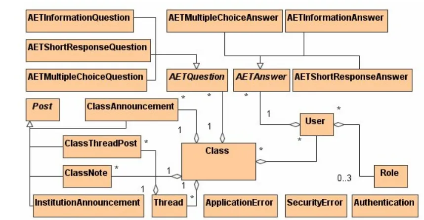
E. Test Manual - A document detailing the test procedures for the OLE project.
F. Web Application Model - A Unified Modeling Language model of the OLE Web
application.
G. Project Gantt Chart - A chronological gantt chart that lists tasks and their
com-pletion times.
Chapter 2
Methodology and Techniques
Throughout the OLE project, different methodologies and techniques into software
en-gineering were required to be researched. The areas researched within this project
consisted of software project management, programming languages, development
envi-ronments and tools, and software project implementation methods and techniques.
Application Programming Interface (API) ‘The set of programming language
constructs or statements that can be coded in an application program to invoke
the specific functions and services provided by an underlying operating system or
service program.’ (Microsoft Developer Network 2003, his/snagloss 1b4x.htm)
Common Language Runtime (CLR) ‘The engine at the core of managed code
ex-ecution. The runtime supplies managed code with services such as cross-language
integration, code access security, object lifetime management, and debugging and
profiling support.’ (Microsoft Developer Network 2003, p.
Netstart/html/cp-gloc.htm)
Database Management System (DBMS) ‘A software system that enables users
to define, create, maintain, and control access to the database.’ (Connolly &
Begg 2002, p. 16)
Dynamic Link Library (DLL) A file containing a library of functions that can be
2.1 Software Project Development 4
memory only once, so it can be accessed by other applications.
Technical Preview Beta An application that allows developers to understand the
application before it is released to the public. It also contains software bugs due
to the fact that it is still under development.
2.1
Software Project Development
Software Project Development consists of processes that make up the development of a
software application. Some of these processes are:
• Requirements Elicitation
• Requirements Analysis
• System Design
• Object Design
• Implementation
• Testing
Firstly, the Requirements Elicitation process focuses on defining the purpose of the
software system, generating functional and non-functional requirements from an initial
problem statement. A functional requirement is an ‘area of fuctionality the system
must support’ (Bruegge & Dutoit 2000, p. 718), whereas a non-functional requirement
is a ‘user-visable constraint on the system’ (Bruegge & Dutoit 2000, p. 724).
Secondly, the Requirements Analysis process uses the generated products from the
Requirements Elicitation process that generates an analysis model that is composed of
three other model:s:
• Functional Model - Use cases and scenarios.
2.2 Software Project Management 5
• Dynamic Model - Statechart and sequence diagrams.
Thirdly, theSystem Designprocess uses the generated products from theRequirements
Analysis andRequirements Elicitation process to generate design goals and decompose
the subsystems. Fourthly, theObject Designprocess uses the subsystem decompositions
to generate a class diagram. Finally, the Implementation process uses the generated
class diagram to produce working source code, which can then be tested via theTesting
process.
2.2
Software Project Management
Software Project Management consists of activities and techniques to monitor and
maintain a certain level of performance in the development of a software project. Some
of the activities in software project management are:
• Scheduling the workload over a period of time;
• Dividing the workload over a range of human resources;
• Defining and manage the risks throughout the project; and
• Documenting the progress, technical specifications, and functional/non-functional
requirements.
The life cycles for software projects vary from organisation-to-organisation, however,
the activities involved are consistent throughout. The Institute of Electrical and
Elec-tronics Engineers (IEEE) have constructed a standard for the development life cycle
within software projects known as theIEEE 1074: Standard for Developing Life Cycle
Processes.
Bruegge & Dutoit (2000, pp. 460-468) describes the IEEE 1074: Standard for
Devel-oping Life Cycle Processes, from the IEEE (1997). Table 2.1 gives the process groups
2.2 Software Project Management 6
Table 2.1: Software processes within the IEEE 1074: Software Developing Life Cycle
Processes
Process Group Process
Project Management Project Initiation
Project Management and Control
Software Quality Management
Pre-development Concept Exploration
System Allocation
Development Requirements
Design
Implementation
Post-development Installation
Operation and Support
Maintenance
Retirement
Integral Processes Verification and Validation
Software Configuration Management
Document Development
Training
The first process group from Table 2.1, Project Management, is designed to monitor
and control the project throughout the software life cycle. The next process,
Pre-development researches the concept through different ways in order to understand and
appreciate the project in more detail. The Development process follows by defining
the software’s requirements, then designing and implementing the software.
Post-development includes the installation of the software, while offering support and
main-tenance. The last processes under Integral Processes are performed throughout the
duration of the project, which include software configuration management,
2.2 Software Project Management 7
2.2.1 Software Process Models
The implementation of a software application has a number of models to approach the
process of software project management. Several software process models were detailed
by Sommerville (2001, pp. 44-50). Specifically, two of these models are:
• The waterfall model - The fundamental activities within the development of a
software project are represented as phases such as requirements specification,
software design, implementation, and testing.
• Evolutionary development - Interleaves the fundamental activities of a software
project. Abstract specifications then create an initial system to be refined with
customer input to satisfy the requirements of the customer.
The main difference between these two models processes is the order in which each
activity occurs. To clarify, using the waterfall process model (Figure 2.1) in an ideal
situation only allows back-tracking to the previous activities when the last activity
has been reached. Whereas, the evolutionary development process model (Figure 2.2)
allows back-tracking between all activities.
2.2 Software Project Management 8
Figure 2.2: TheEvolutionary Development Process Model
2.2.2 Software Project Documentation
Documentation of a software application is an important component within every
soft-ware project. It relates to softsoft-ware project management by allowing project managers
to record alterations throughout the project. Within an organisation, executives
mon-itor and keep progress reports and information relating to all projects. Another reason
for keeping documentation is so that if project staff leave the organisation, new project
staff can research the documentation and understand the project.
The four documents that will be described in detail are:
• Requirements Analysis Document(RAD) - Describes system’s functional and
non-functional requirements and serves as a contract between the developers and
the client. The audience for the RAD includes the client, the users, project
management, the system analysts, and the system designers (Bruegge & Dutoit
2004, pp. 151-153).
• System Design Document (SDD) - Describes the design by subsystem
decomposi-tion (with the use of UML class diagrams), hardware and software mapping (with
the use of UML deployment diagrams), access control, control flow mechanisms,
data management, and boundary conditions. The audience for the SDD includes
system architects, project management, and the developers who implement each
subsystem (Bruegge & Dutoit 2004, pp. 282-284).
2.2 Software Project Management 9
followed for subsystem interfaces, decomposition of subsystems into packages and
classes, and class interfaces. The audience for the ODD includes system architects,
developers who implement the subsystem, and testers (Bruegge & Dutoit 2004,
pp. 373-379).
• Test Manual- Describes the scope, approach, and records the differences between
the expected output and the results of the test. The audience for the test manual
includes developers who implement the system, testers, and system architects
(Bruegge & Dutoit 2004).
• User Manual describes the instructions in using the software application. This
is so that users can refer to it for information and instructions on the software
application. The audience for the User Manual includes users that interact with
the system, developers, and testers (Bruegge & Dutoit 2004).
From Section 2.2.1, it was mentioned that this project would follow the evolutionary
development process model. This means that these four documents are not completed
sequentially. That is, the SDD does not have to commence before the RAD, or the
ODD before the SDD. To clarify, these documents will interleave between each other
until completed.
Commonly, however, the document that commences first is the RAD, since it defines
the functions and features that will exist within the software project.
Requirements Analysis Document
Figure 2.3 outlines the template used for the RAD. It has been modified from its original
outline, specified by Bruegge & Dutoit (2004, p. 152), so that its section headings fit
2.2 Software Project Management 10
Requirements Analysis Document
1. Introduction
1.1 Purpose of the System
1.2 Scope of the System
1.4 Definitions, Acronyms, and Abbreviations
1.6 Overview
2. Current System
2.1 Overview
2.2 Functions and Features
3. Proposed System
3.1 Overview
3.2 Functional Requirements
3.3 Non-Functional Requirements
3.3.1 Usability
3.3.2 Reliability
3.3.3 Performance
3.3.4 Supportability
3.3.5 Implementation
3.3.6 Interface
3.3.7 Operation
3.4 System Models
3.4.1 Scenarios
3.4.2 Use Case Models
3.4.3 Object Model
3.4.4 Dynamic Models
3.4.5 User Interface
Glossary
Figure 2.3: The outline of the Requirements Analysis Document (RAD)
Section 1 of the RAD involves an introduction into the system, providing information
about its purpose and scope. Section 2 provides an analysis of a current system’s
functions and features. Section 3 is the largest section of this document. It lists the
functional and non-functional requirements that will exist for the proposed system.
The non-functional requirements are made up of the system’s usability, reliability,
2.2 Software Project Management 11
details system models using UML diagrams, which describe the system with respect to
the functional and non-functional requirements.
System Design Document
Figure 2.4 outlines the template used for the SDD. It has been modified from its original
outline, specified by Bruegge & Dutoit (2004, p. 283), so that its section headings fit
the OLE project.
System Design Document
1. Introduction
1.1 Purpose of the System
1.2 Design Goals
1.3 Definitions, Acronyms, and Abbreviations
1.5 Overview
2. Current Software Architecture
3. Proposed Software Architecture
3.1 Overview
3.2 Subsystem decomposition
3.3 Hardware/Software Mapping
3.4 Persistent Data Management
3.5 Access Control and Security
3.6 Global Software Control
3.7 Boundary Conditions
4. Subsystem Services
Figure 2.4: The outline of the System Design Document (SDD)
Section 1 of the SDD is similar to the RAD’s introduction. It provides an introduction
to the system’s design goals, in addition to describing purpose of the system. Section
2 briefly details the current system’s architecture. Section 3 details the proposed
sys-tem’s overall architecture. This consists of decomposing and detailing the subsystems,
mapping hardware and software, defining how persistent data is managed, security and
access control features, how the software is controlled, and the conditions of start-up
2.2 Software Project Management 12
Once the first revision of this document started to take shape, the implementation of
this project was commence.
Object Design Document
Figure 2.5 outlines the template used for the ODD. It has been modified from its original
outline, specified by Bruegge & Dutoit (2004, p. 376), so that its section headings fit
the OLE project.
Object Design Document
1. Introduction
1.1 Object Design Trade-Offs
1.2 Interface Documentation Guidelines
1.3 Definitions, Acronyms, and Abbreviations
1.4 Overview
2. Packages
3. Class Interfaces
Figure 2.5: The outline of the Object Design Document (ODD)
Section 1 of the ODD introduces the reader to the object design trade-offs and
doc-umentation guidelines for the interface. Section 2 provides a detailed description of
packages within the system. Section 3 details the class interfaces, which are used
throughout the system.
This document flows through a number of revisions in an attempt to increase efficiency
and decrease complexity of the class interfaces.
Test Manual
Figure 2.6 outlines the sections used for the Test Manual. It is a combination of the
two documents,Test Plan and Test Case Specification, specified by Bruegge & Dutoit
2.2 Software Project Management 13
Test Manual
1. Introduction
2. Testing
2.1 Unit Testing
2.2 Integrated Testing
Appendix A. Source Code
Figure 2.6: The outline of the Test Manual
Section 1 provides a brief introduction of how the testing will be carried out. Section
2 is split into unit and integrated testing. Unit testing tests the classes individually
and integrated testing tests the user interfaces, which integrates the classes from the
project.
2.2.3 Software Project Schedule Management
A software project’s schedule is vital to its development. Deadlines can be created so
that developers stay on time. This project activity can only be set by individuals with
experience in the respective software field. For this project, seven components were
fashioned:
• Documentation - Lists the documents that are required to be completed and in
which order.
• Requirements Elicitation and Analysis- Lists the process required to produce the
requirements and analyse them.
• Design - Lists the process required to produce the design of the system.
• Training - Lists the languages required to be learnt before implementation.
• Implementation - Lists the steps involved in implementing the system.
• Testing - Lists the process required to test two other components. They are:
2.3 Programming Languages 14
– Integration Testing - All of the components with the system, working
to-gether.
• Deployment - Lists the process required to deploy the system.
2.2.4 Software Project Risk Management
All projects, software or other, have unexpected issues that may arise throughout its
development. Risk Management is a common safeguard that ensures that these issues
are minimised or averted. Sommerville (2001, pp. 84-91) describes some of the risks
involved when developing a software project. He divides risk management into three
sections:
• Risk Identification - Identifies and lists the risks that may be encountered within
the design and implementation.
• Risk Analysis - Lists and analyses the risks that may affect or jeopardise the
project; along with the probability of affect upon, and the effect it may impose
on the project.
• Risk Strategy - Lists the risks from the risk analysis section and strategies that
may be carried out in order to avoid such a danger.
2.3
Programming Languages
This section introduces the programming models and languages that were researched
in order to implement a modern software application. Firstly, Microsoft .NET and
Microsoft .NET Framework will be detailed, while then describing ASP.NET, C# .NET,
ADO.NET, XML, SQL, HTML, and CSS. Their acronyms will also be defined in each
respective sub-section.
The primary languages will be described in greater depth, introducing their main
2.3 Programming Languages 15
Microsoft .NET
TheMicrosoft .NET platform is used for building, running, and experiencing the next
generation of distributed applications. It extends over clients, servers, and services.
Microsoft Corporation (2001a) outlines Microsoft .NET and that it consists of:
• A unified programming model - Enables developers to build applications and XML
Web services;
• Client software - This helps developers deliver a deep and compelling user
expe-rience across a family of devices;
• Servers - Integrates, executes, operates, and manages applications and XML Web
services;
• XML Web services - Helps developers create a simple and integrated user
expe-rience; and
• Tools - Are used to develop Windows and Web applications, and XML Web
services.
Microsoft .NET Framework 1.1
The Microsoft .NET Framework is the programming model of the Microsoft .NET
platform. It allows for building, deploying, and running applications and XML Web
services. It also manages much of the inner workings of .NET, enabling developers
to concentrate on writing business logic code for their software applications (Microsoft
Corporation 2001a). The Microsoft .NET Framework consists of two main components:
• Common Language Runtime (CLR)
• Class Libraries
Figure 2.7 depicts the Microsoft .NET Framework and how its components exist with
2.3 Programming Languages 16
Figure 2.7: The Microsoft .NET Framework’s components
The Common Language Runtime (CLR) is the core engine responsible for services
such as language integration, and memory, process, and thread management. It also
has the role of managing development time features such as; strong type naming, cross
language exception handling, and dynamic binding. This reduces the amount of code
to be written by developers in order to turn business logic into reusable components
(Microsoft Corporation 2001b).
The Class Libraries provide what the name suggests, a library of classes for the use of
developers. Microsoft Corporation (2001b) lists some of these as:
• Base classes- Provide standard functionality for developers such as, string
manip-ulation, input/output, network communications, thread management, text
man-agement, and many others;
• Data classes - Support data management and include SQL classes for
manipulat-ing data stores through a standard SQL interface;
• XML classes - Enable XML data manipulation, searching, and translations;
• Web Forms classes - Include the classes that enable developers to rapidly create
Web graphical user interface (GUI) applications; and
• Windows Forms classes - Support developers in creating GUI for Windows. This
provides a common, consistent development interface across all languages
2.3 Programming Languages 17
2.3.1 Microsoft Active Server Pages .NET 1.1
Microsoft Active Server Pages .NET (ASP.NET) is more than the next version of
Mi-crosoft Active Server Pages 3.0 (ASP); it is a Web development platform that provides
the services that are required for developers to design and build enterprise-class Web
applications (Microsoft Corporation 2004a).
The following sub-sections will briefly describe some of the main components within
ASP.NET.
Web Forms
Microsoft Developer Network (2003, p. Netstart/html/cpglow.htm) defines aWeb Form
as an ‘ASP.NET page framework, which consists of programmable Web pages ... that
contain reusable server controls’. To clarify, a Web form is a Web page that is compiled
dynamically when it is requested by a client. Once a client requests the page, the
ASP.NET Web server executes the methods defined by the programmer, with its result
sent back to the client.
Web User Controls
Microsoft Developer Network (2003, p. Netstart/html/cpglou.htm) defines aWeb User
Control as:
‘A server control that is authored declaratively using the same syntax as an
ASP.NET page and is saved as a text file with an .ascx extension. User
controls allow page functionality to be partitioned and reused. Upon first
request, the page framework parses a user control into a class that derives
from System.Web.UI.UserControl and compiles that class into an assembly,
which it reuses on subsequent requests.’
To clarify, a Web user control is identical to a Web form, however, they are designed to
2.3 Programming Languages 18
throughout the site. So that the menu does not have to be repeated for each page, a
Web user control (menu.ascx, for example) is included at a specific location within all
ASP.NET pages.
Code-Behind
Code-Behind can be defined in two forms, files and classes. A code-behind file is ‘a
code file containing the page class that implements the program logic of a Web Forms
or ASP.NET mobile Web Forms application’ (Microsoft Developer Network 2003, p.
Netstart/html/cpgloc.htm). Acode-behind class is ‘a class that is accessed by an .aspx
file, but resides in a separate file (such as a .dll or .cs file). For example, you can write a
code-behind class that creates an ASP.NET custom server control, contains code that is
called from an .aspx file, but does not reside within the .aspx file’ (Microsoft Developer
Network 2003, p. Netstart/html/cpgloc.htm).
This defines a very important advantage for programmers since the logic of an ASP.NET
page can exist outside of the page’s presentation code. Linking pages to classes also
allows programmers to develop powerful methods and properties that interact with the
page in a more logical manner.
2.3.2 Microsoft C# .NET 1.1
Microsoft C# .NETis the most common programming/scripting language for ASP.NET
and other methods. It is a modern, object-oriented, and type-safe language and
en-ables programmers to build a wide range of different applications for the new Microsoft
.NET platform. C#, pronounced ”see-sharp”, is designed to enable rapid development
to the C++ programmer without sacrificing the power and control that have been the
trademarks of C and C++ (Microsoft Corporation 2004e).
In 2001, the International Standards Office (ISO) received Microsoft C# .NET to be
standardised. In April of 2003, it was ratified as ISO/IEC 23270 (Microsoft Corporation
2.3 Programming Languages 19
In the following sub-sections, a brief description will be given to some of the main
concepts and components within C# .NET.
Value-Types versus Reference-Types
In order to explain value and reference-types correctly, their definitions must be
de-scribed. A value-type is a ‘data type that is represented by the type’s actual value’
(Microsoft Developer Network 2003, Netstart/html/cpglov.htm). To clarify, changing
a value-type variable changes the actual value of the variable. Some value-typed
data-types areint,char, enumerations, and structures.
Areference-type is a ‘data type that is represented by a reference (similar to a pointer)
to the type’s actual value’ (Microsoft Developer Network 2003,
Netstart/html/cp-glor.htm). To clarify, a reference-type pointed to a place in memory where the actual
value was held. This allows multiple reference-type variables to point to the same
location, each changing the same actual value. All classes are reference-types.
Interfaces
An interface provides a framework to which a class must conform. That is, it supplies
a definition of properties and/or methods which must be implemented by any derived
class. Listing 2.1 shows an example of an interface.
Listing 2.1: Interface example in C#
1 public i n t e r f a c e IManage
2 {
3 bool i s R e a d o n l y
4 {
5 g e t ;
6 s e t ;
7 }
2.3 Programming Languages 20
11 }
Classes
A class within C# is made up of methods (virtual and abstract), attributes, properties,
and static members. These class members are identical to C++, with minor changes.
One of these changes is that in C++, a class can only inherit one other class. In C#, his
ability has been replaced by enabling a class to inherit an infinite amount of interfaces.
Garbage Collection
Garbage collection is not a new concept within programming languages. It is ‘the
process of transitively tracing through all pointers to actively used objects in order
to locate all objects that can be referenced, and then arranging to reuse any heap
memory that was not found during this trace’ (Microsoft Developer Network 2003, p.
Netstart/html/cpglog.htm).
C and C++ do not have garbage collection. When memory was allocated to a variable,
it must be deallocated. Listing 2.2 demonstrates an example of this.
Listing 2.2: C/C++ example of how and where memory is allocated and deallocated
1 i n t main ( )
2 {
3 i n t mem [ ] = new i n t[ 1 0 0 ] // A l l o c a t e d memory o f 100 i n t s 4 // mem = n u l l ; // Would n o t d e a l l o c a t e t h e memory ( no
g a r b a g e c o l l e c t i o n )
5 d e l e t e mem; // A l l o c a t e d memory now d e a l l o c a t e d
6 }
C#, however, has this feature, and the allocated memory is deallocated once it is no
longer referenced by a variable. Listing 2.3 demonstrates an example of this.
Listing 2.3: C# example of where memory is allocated and deallocated
2.3 Programming Languages 21
2 {
3 i n t[ ] mem = new i n t[ 1 0 0 ] ; // A l l o c a t e d memory o f 100 i n t s 4 mem = n u l l; // A l l o c a t e d memory now d e a l l o c a t e d ( g a r b a g e
c o l l e c t i o n )
5 }
2.3.3 Microsoft Active Data Objects .NET 1.1
Microsoft Active Data Objects .NET, also known as ADO.NET, is defined by Microsoft
Developer Network (2003, p. Netstart/html/cpglog.htm) to be:
‘The suite of data access technologies included in the .NET Framework class
libraries that provide access to relational data and XML. ADO.NET
con-sists of classes that make up the DataSet (such as tables, rows, columns,
relations, and so on), .NET Framework data providers, and custom type
definitions (such as SqlTypes for SQL Server).’
To clarify, ADO.NET consists of data connectivity features via the .NET Framework in
the form of database and XML. The .NET Framework namespace that provides these
class libraries is System.Data.
2.3.4 Extensible Markup Language
Extensible Markup Language (XML) is a simple and very flexible text format derived
from the language, Standard Generalized Markup Language (SGML). It is playing an
increasingly successful and important role in the exchange of a wide variety of data on
the Web and elsewhere.
Microsoft Developer Network (2003, p. Netstart/html/cpgloe.htm) defines XML as
providing ‘a uniform method for describing and exchanging structured data that is
independent of applications or vendors.’ XML specification also provides more complex
2.3 Programming Languages 22
Extensible Markup Language Schema Definitions
Extensible Markup Language Schema Definitions (XSD) are a tool to structure and
maintain that structure (through validation) in XML data files. This is done by defining
data-types to the different nodes’ attributes and elements. Also, it defines the structure
of the node by having a set of rules that determine how many elements and attributes
exist under the root node.
Extensible Stylesheet Language Transformations
Extensible Stylesheet Language Transformations (XSLT) is another tool for XML files
that can manipulate the way in which the data is displayed to the user. It allows
the XML data to be unchanged so that other XSLT files can manipulate the data
dynamically.
2.3.5 Structured Query Language
Structured Query Language (SQL) is the standard language for database operations
and commands. Simple programming syntaxes allow tables, rows, and columns to be
added to a database easily and efficiently. SQL also allows fast and efficient listings of
database entries to be viewed by users.
Stored Procedures (Microsoft SQL Server specific)
Microsoft Developer Network (2003, architec/8 ar da 0nxv.htm) defines a stored
pro-cedure as a ‘precompiled collection of Transact-SQL statements stored under a name
and processed as a unit’. To clarify, it stores a precompiled query within the database
as the database changes. This increases server effeciency by stopping the requirement
2.3 Programming Languages 23
XML Support
The support given by Microsoft SQL Server 2000 for XML is provided by transforming
database data in the form of an XML document. This XML document can then by read
and transformed by the application that requests the data. Listing 2.4 demonstrates
a stored procedure that implements aFOR XML EXPLICIT mode. Listing 2.5 details an
example XML document that would be compiled from Listing 2.4.
Listing 2.4: FOR XML EXPLICIT stored procedure
1 CREATEPROCEDURE dbo . F i n d C l a s s
2 (
3 @ c l a s s I D CHAR( 1 0 )
4 )
5 AS
6 SELECT
7 1 AS Tag ,
8 NULL AS Parent , 9 NULL AS [ C l a s s e s ! 1 ] ,
10 NULL AS [ C l a s s ! 2 ! c l a s s I D ] , 11 NULL AS [ C l a s s ! 2 ! Name ! e l e m e n t ] , 12 NULL AS [ C l a s s ! 2 ! d e n y O t h e r U s e r s ] 13 UNION ALL
14 SELECT
15 2 AS Tag ,
16 1 AS Parent ,
17 NULL,
18 C l a s s e s . c l a s s I D ,
19 C l a s s e s . className ,
20 C l a s s e s . d e n y O t h e r U s e r s
21 FROM C l a s s e s
22 WHERE c l a s s I D=@ c l a s s I D 23 FOR XML EXPLICIT
Listing 2.5: Output from the stored procedure in Listing 2.4
1 <C l a s s e s>
2 <C l a s s c l a s s I D=”ENG4111” d e n y O t h e r U s e r s=” 1 ”>
2.4 Development Environments and Tools 24
4 </ C l a s s>
5 </ C l a s s e s>
2.3.6 Hyper-Text Markup Language
HyperText Markup Language (HTML) is made up of tags such as <h1> and </h1> to
structure text into headings, paragraphs, images, lists as well as hypertext links so that
data and information can be displayed in an appropriate and eye catching method.
HTML is another language that is derived from the language SGML.
2.3.7 Cascade Style Sheeting
Cascading Style Sheets (CSS) is a simple programming mechanism used for adding
styles to HTML Web documents. These include colours, fonts, spacing, table sizing,
as well as a number of other style attributes. It was designed to speed up Web page
development by specifying a style class in place of typing code repeatedly.
2.4
Development Environments and Tools
Every software project requires an environment under which development occurs. Tools
are also important in assisting in the development of the project. The following
sub-sections will briefly describe the environments and tools utilized within this project.
2.4.1 Microsoft Visual Studio .NET 2003
Microsoft Visual Studio .NET 2003 delivers the developer productivity required to
deliver a wide range of professional software applications. ItsIntegrated Development
Environment(IDE) provides a consistent interface for all languages, includingMicrosoft
Visual Basic .NET, Microsoft Visual C++ .NET, Microsoft Visual C# .NET, and
2.4 Development Environments and Tools 25
to design and build rich Windows-based applications and dynamic Web applications
that render in any browser (Microsoft Corporation 2004f).
2.4.2 Microsoft ASP.NET Web Matrix
Microsoft ASP.NET Web Matrix allows developers to write ASP.NET code productively
and efficiently. Designed and developed by some of the team that created ASP.NET, it
has been completely written using the Microsoft .NET Framework and Microsoft C#
.NET (Microsoft Corporation 2004b). Although it is not as powerful and diverse as
Microsoft Visual Studio .NET 2003, it offers subtle advantages.
The Matrix Class Browser is one of these advantages as it lists all the classes (along
with their properties, methods, and events) within the Microsoft .NET Framework.
2.4.3 Microsoft Windows Server 2003
Microsoft Windows Server 2003 is a multipurpose operating system capable of handling
a diverse set of server roles. Some of these server roles include the ability to be a Web
server with Web application services and a mail server. Microsoft Windows Server 2003
is the first operating system to completely integrate the Microsoft .NET Framework on
installation (Microsoft Corporation 2002b).
2.4.4 Microsoft Internet Information Service 6.0
Internet Information Services 6.0 (IIS) is a powerful Web server which is included
with all Microsoft Windows Server 2003 editions. It provides a highly reliable,
man-ageable, scalable, and secure Web application infrastructure and environment. IIS
allows developers to quickly and easily deploy Web sites as well as providing a
high-performance platform for applications built using Microsoft ASP.NET and the
2.4 Development Environments and Tools 26
2.4.5 Microsoft SQL Server 2000 and 2005
Microsoft SQL Server 2000 is an industry leader in database development and
de-ployment. Its speed and efficiency in adding, deleting, altering, and searching data
has made its mark in theDatabase Management System (DBMS) industry (Microsoft
Corporation 2002c).
TheMicrosoft Desktop Engine 2000 (MSDE) is a data engine built and based on core
Microsoft SQL Server 2000 technology for database and application developers. It is a
reliable storage engine and query processor for desktop extensions of enterprise
appli-cations. The common technology base shared between Microsoft SQL Server 2000 and
MSDE allows developers to build applications that can scale seamlessly from portable
computers to multiprocessor clusters. An example is the Microsoft SQL Server 2000
Enterprise Edition database server (Microsoft Corporation 2003c).
Microsoft has recently released a technical preview beta version of their upcoming
Microsoft SQL Server 2005. This technical preview has been released as an Express
Edition which is the equivalent to MSDE, described above, with its core engine their
primary difference. The SQL Server 2005 engine offers (Microsoft Corporation 2003b):
• .NET Framework Hosting - Developers will be able to create database objects
using languages such as Microsoft Visual C# .NET.
• XML Technologies - Native support for storage and query of XML documents.
• Transact-SQL Enhancements - Including error handling and recursive query
ca-pabilities.
2.4.6 Microsoft Developer Network
Throughout the history of Microsoft, a very important and vital tool has been offered
(free of charge) to all public developers. The Microsoft Developer Network (MSDN)
offers a substantial information database for Microsoft products and Application
2.5 Software Project Implementations 27
recently, the .NET Framework. This information is offered in the form of white-papers,
case studies, source code examples, and class interface descriptions.
Microsoft makes this library available on disc and on the Internet (Microsoft Developer
Network 2004). With this information, programmers can develop their software so that
it works within the Windows platform.
As an extension to MSDN, Microsoft offers discussion newsgroups where Microsoft
employees, Microsoft’sMost Valuable Professionals (MVPs), and volunteers offer their
advice and help in the situations where developers encounter difficulties or problems.
2.5
Software Project Implementations
Throughout the software industry, there are three implementation types:
• Executable Applications
• Web Site
• Web Applications
Executable Applications
An Executable Application is an executable file that can be a versatile, dynamically
formed computer program that allows for full interaction with data. These programs
are subject to acute synchronisation errors when accessing and communicating with
databases. Each executable application is platform dependent, meaning that it requires
a specific operating system in order to operate correctly. In addition, each computer
must have an executable file available to access and manipulate data. An Executable
2.5 Software Project Implementations 28
Web Sites
AWeb Siteis a neat and orderly set out page that statically displays data and allows a
limited interaction with data. These pages have a restricted range of data manipulation
techniques. A Web site can be used via the Internet or an Intranet network by using a
third party Web browser and can be identified by the file extensions.htm and .html.
2.5.1 Web Applications
AWeb Application is a combination of a Web site and an executable application. This
means that Web application can be a neat and orderly laid out page that dynamically
displays and manipulates data. It can be used via the Internet or an Intranet network
by the use of a third party Web browser. A Web application can be identified by the
file extension .asp,.aspx,.jsp,.cgi, and.php.
Web application’s are more complex than they appear. When implementing, they
can be divided into a tier application architecture, which can range from a one-tier
2.5 Software Project Implementations 29
Figure 2.8: The tier application architectural designs
Source: Coleridge (2002, Figure 1)
The business rules component shown above (Figure 2.8) manipulates data from the data
source so that other components can use the data. Common to all tier architectures
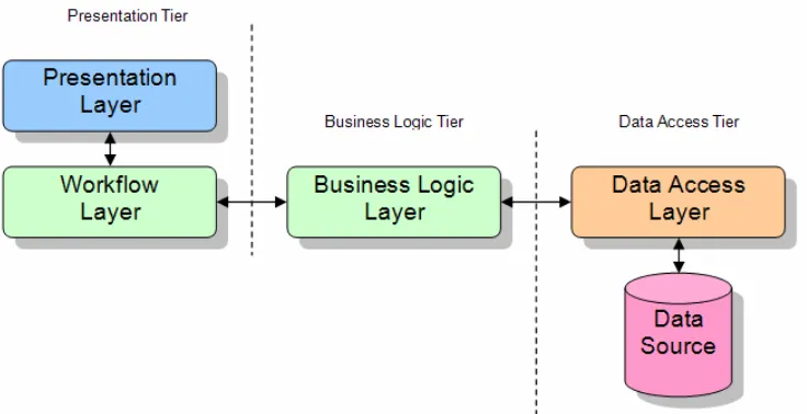
are the different layers each possess. The four layers are:
• Presentation Layer - This layer presents data to the user via a user interface.
• Workflow Layer - The business rules on the client-side. That is, it controls the
user’s input and other processes on the client.
• Business Logic Layer - The business rules on the server-side. That is, it controls
the manipulation and flow of data on the server.
• Data Access Layer - Allows the business rules access to the data source.
One-Tier Architecture
The one-tier architecture contains all layers inside the application itself. In a
large-scale environment, this type of application would be difficult to maintain. This type of
2.5 Software Project Implementations 30
Two-Tier Architecture
The two-tier architecture splits the application by creating theData Access Layer
(sec-ond tier). This allows the programmer to implement an application with multi-user
access more easily than with a one-tier system. This type of architecure is suitable for
small to medium systems that allows multiple users to access the system at the same
time.
Three-Tier Architecture
The three-tier architecture splits the application again by creating theBusiness Logic
Layer (second tier) alongside the Data Access Tier (third tier). This layer not only
contains the code to determine the data’s purpose, but also code that determines how
and when to manipulate the data.
This architecture was chosen as the back-bone of this project, because it allows:
• Users to interact with the application
• The server to manipulate the data to suit the database
• The database to store and serve data
• Users to access data simultaneously
N-Tier Architecture
Then-tier architecture is very similar to the three-tier architecture. The only difference
is, in its decision to split its layers into a greater number, the work load is decreased
in different processes. One example is the spliting of theData Access Layer up into an
Chapter 3
Software Design
This chapter describes the design behind the system and database architectures of the
OLE project. It also identifies the Microsoft .NET Framework components and
Section 3.1 explains the thought behind the system architecture, while Section 3.2
ex-plains the database architecture. Finally, Section 3.3 describes the different namespaces
and members of the Microsoft .NET Framework.
Database Management System (DBMS) ‘A software system that enables users
to define, create, maintain, and control access to the database.’ (Connolly &
Begg 2002, p. 16)
3.1
System Architecture
In Chapter 2, specifically Section 2.5.1, the different application architectures were
discussed. The OLE utilized the three-tier architecture, shown in Figure 3.1, which
3.1 System Architecture 32
Figure 3.1: The three-tier application architecture
Presentation Tier
This tier (subsystem) consists of two layers. They are the Presentation and Workflow
layers. ThePresentation layer consists of code that presents the data to the user. The
languages used under this layer were HTML and CSS.
TheWorkflow layer consists of code that creates and manipulates data to fit within the
Presentation layer. The language used was combination of C# .NET and ASP.NET
Business Logic Tier
This tier involves a layer called theBusiness Logic layer. This layer consists of classes
3.1 System Architecture 33
Data Access Tier
This tier consists of theData Access layer. It provides classes that can realise the
stor-age, retrieval, and query of persistent objects within theData Source. The languages
used here were ADO.NET and SQL.
3.1.1 System-to-Data Relationship
Since the OLE was also a research project, a hybrid method was taken towards the
relationship between the system and data. Two methods were used to manage data
utilized, specifically XML files and an SQL Server database.
In order to create this hybrid method, a sealedclass was designed to offer properties
and methods relating to both SQL and XML data management. The name given to
this class reflected its purpose; to offer a bridge between the system and data. The
name,DataBridgewas created.
Since SQL is very broad in its method calls, its connection class was offered as a
property, so that its calls can be manually invoked. XML was used quite differently.
It held two properties that gave the class and institution directories. These directories
sorted the XML files. The class also offered many methods that returned next files’
paths and existing files’ paths.
3.1.2 Data Storage Techniques
Two types of data storage techniques were used within the OLE project. These two
techniques are the most used methods within the development industry. They are:
• SQL databases; and
3.1 System Architecture 34
In order for these two techniques to exist within the project, a programming model
that utilized these two techniques was required.
Section 3.2 describes the SQL database’s design, but not its connection to the XML file
design. It will be noted here that within Section 3.4 within the SDD (Appendix C),
the design and structure of the XML file and SQL database is documented. The SQL
database is used for effeciently recovering data, since the database only holds superficial
and important information (i.e. small amounts of information or information that
will constantly be accessed). The XML files hold all of the information so that both
techniques do not have to be called in order to get retrieve the requested information.
An example:
An assignment will have an identifier (ID), a due date, and a question to
accompany it (simplified example). The SQL database will hold the:
• ID - A unique number to create a link between programming calls.
• Due Date - A small value that will be constantly called apon.
The XML file will hold all the values so:
• ID - As seen above.
• Due Date - Holds and the SQL database does not have to be called in
order to retrieve this value.
• Question - Is a large field that can be any size.
There are two main reasons why this programming model was designed. They are:
• To learn both data storage techniques; and
• As a way to lessen the complication of the SQL database since they can only hold
3.2 Database Architecture 35
3.2
Database Architecture
Before a database can be completed, it must pass through a number of design steps.
Connolly & Begg (2002, pp. 420-421) describes the database design methodology, which
was used in order to generate a database for the OLE. This methodology is divided
into three main sections, each containing steps:
• Conceptual Database Design - ‘The process of constructing a model of the
infor-mation used in an enterprise, independent of all physical considerations.’ (Connolly
& Begg 2002, p. 419)
– Step 1 - Build a local conceptual data model.
• Logical Database Design - ‘The process of constructing a model of the
informa-tion used in an enterprise based on a specific data model, but independent of
a particular DBMS and other physical considerations.’ (Connolly & Begg 2002,
p. 419)
– Step 2 - Build and validate a local logical data model.
– Step 3 - Build and validate a global logical data model.
• Physical Database Design - ‘The process of producing a description of the
im-plementation of the database on secondary storage...’ (Connolly & Begg 2002,
p. 419)
– Step 4 - Translate the global logical data model.
The steps shown above also split into sub-steps. Figure 3.2 display these steps in further
3.2 Database Architecture 36
Step 1 - Build a local conceptual data model
Step 1.1 - Identify entity types
Step 1.2 - Identify relationship types
Step 1.3 - Identify and associate attributes with entity or relationship types
Step 1.4 - Determine attribute domains
Step 1.5 - Determine candidate and primary key attributes
Step 2 - Build and validate a local logical data model
Step 2.1 - Derive relations for local logical data model
Step 2.2 - Validate relations using normalization
Step 2.3 - Define integrity constraints
Figure 3.2: The steps in the Database Design Methodology (Steps 1 to 2)
This section will follow through the described steps, informing how the OLEs database
was generated.
Step 1.1 - Identify entity types
Connolly & Begg (2002, p. 331) defines an entity type as, ‘a group of objects with
the same properties, which are identified by the enterprise as having an independent
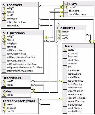
existence’. Using this definition, the OLE has the following entity types:
• Users - An individual that contributes to the system.
• Classes - A course for users to enrol in and contribute.
• Roles - Three roles that define a user’s type of contributions.
• AETQuestions - An Assignment, Exam, or Tutorial question within a class.
• AETAnswers - An answer to an AETQuestion
3.2 Database Architecture 37
Step 1.2 - Identify relationship types
Connolly & Begg (2002, p. 334) defines a relationship type as, ‘a set of meaningful
associations among entity types’. With this definition, the OLE has the following
relationship types:
Users (1..1) Creates. (0..*) AETQuestions
A Usercan create zero-to-manyAETQuestion(s). An AETQuestioncan have oneUser.
Users (0..*) Maintains. (0..*) Classes
A Usercan maintain zero-to-many Class(es). A Classcan have zero-to-many User(s). Users (0..*) Supervises. (0..*) Users
A Usercan supervise zero-to-many User(s). A Usercan be supervised by zero-to-many User(s). Users (1..1) Owns. (0..*) AETAnswers
A Usercan own zero-to-manyAETAnswer(s). An AETAnswer can have oneUser.
Users (0..*) Has. (0..*) ThreadSubscriptions
A Usercan have zero-to-manyThreadSubscription(s). A ThreadSubscriptioncan have zero-to-manyUser(s). Classes (0..*) Has. (0..*) Users
A Classcan have zero-to-many User(s). A Usercan have zero-to-manyClass(es). Classes (1..1) Has. (0..*) AETQuestions
A Classcan have zero-to-many AETQuestion(s). An AETQuestioncan have oneClass.
Roles (0..3) Assigns . (0..*) Users
3.2 Database Architecture 38
Step 1.3 - Identify and associate attributes with entity or relationship types
Connolly & Begg (2002, p. 338) defines an attribute as, ‘a property of an entity or a
relationship type’. With this definition, Table 3.1, 3.2, and 3.3 will detail the attributes
that were used within each entity.
Table 3.1: The attributes within the entity typesUsers,AETQuestions, and
AETAn-swers
Users AETQuestions AETAnswers
userID aetQID aetQID
firstName classID classID
middleName aetQType aetQType
lastName aetQTitle userID
password aetQDescription aetASubmittedDate
dob aetQQuestionType aetAMarked
postalStreet aetQViewQuestionDateTime
postalSuburb aetQDueDateTime
postalState aetQHaltSubmissionDateTime
postalPostcode aetQViewMarkedAnswersDateTime
postalCountry aetQAmountOfQuestions
phoneNumber
mobileNumber
emailAddress
Table 3.2: The attributes within the entity typesClasses, Roles, and
ThreadSubscrip-tions
Classes Roles ThreadSubscriptions
classID rolesID classID
className threadID