Sarawak, Malaysia,22-25 July 2002 © 2002 WEC
Characterisation of Chip-On-Board (COB) Encapsulate Epoxies Used in the Printed
Circuit Board Assembly (PCBA) Industry Using Variable Frequency Microwave (VFM)
Facilities
H S Ku*, F Siu
#, P L Mok
+, E Siores**, J A R Ball
##*
Faculty of Engineering and Surveying, University of Southern Queensland, West Street, Toowoomba, 4350 Australia
#
PhD Candidate, Industrial Research Institute, Swinburne, Swinburne University of Technology, Australia; Lecturer, Kwun Tong Campus, Hong Kong Institute of Vocational Education, Hong Kong, China
+
Project Manager, Approach Industries Limited, Hong Kong, China
**Professor and Executive Director, Industrial Research Institute Swinburne (IRIS), Swinburne University of Technology (SUT), Hawthorn, VIC 3122, Australia
##
A/Prof & Head, Electrical, Electronic & Computer Engineering, University of Southern Queensland (USQ), West Street, Toowoomba, 4350 Australia
E-mail: [email protected]
ABSTRACT: In the printed circuit board assembly (PCBA) industry, integrated circuit (IC) dies are attached onto the printed circuit board (PCB) with epoxy. The die pads are first connected to the PCB tracks with gold or aluminium wires, utilising an ultrasonic wire-bonding machine. The dies are then coated with thermally cured epoxy. The chip-on-board (COB) is finally placed in an electrical oven for baking at certain temperature for a certain period of time, depending upon the type of epoxy used, until the adhesive is completely cured. The baking process using an electrical oven is time-consuming and costly. An alternative way of curing the epoxy is desirable searched. A variable frequency microwave (VFM) source is identified as the possible solution. The first step in curing the epoxy using VFM heating is to find out the best frequency to process the materials in microwaves and this is termed as ‘characterisation’ of the epoxy by the VFM oven manufacturers. Two VFM facilities were employed to perform the characterisation. One is in the frequency range of 2 – 8 GHz and the other is in the frequency range of 6.5 – 18 GHz. By using these two facilities, the best frequency rangeto process an epoxy by VFM can be identified. Two high quality and commonly epoxy resins, Uniset adhesive and Hysol encapsulant were chosen for consideration. The two resins were then characterised by VFM facilities. From the graphs of the characterisation, a better resin of the two can be identified.
1. Introduction
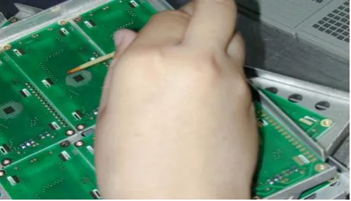
Printed circuit board assembly (PCBA) has been widely used in the electronics industry. In the production of PCBA, in order to reduce the size of the product and minimise space, a bare integrated circuit (IC) chip is often bonded onto a printed circuit board (PCB). The die is usually placed either manually or automatically on the PCB using thermally and electrically conductive epoxy to fix the relative position of the former to the latter as depicted in Figure 1. Aluminium or gold wires are then connected between PCB tracks and die pads using an ultrasonic welding wire bonding machine. After function tests, the die will be coated with thermally curable epoxy. This is referred to as “encapsulation” (Mair, 1993). In order to decrease the viscosity of the epoxy, the PCB board will be placed on top of a hot plate during the dispensing of the adhesive as shown in Figure 2. The amount of epoxy used will depend on the products (PCBs) and the type of adhesive used. The chip-on-board (COB) will then be placed in a conventional electrical oven for baking at certain temperature for a certain period of time, depending on the type of epoxy used, until the epoxy is completely cured. The PCBs are then bent to a pre-selected curve, as a bending test to simulate real application conditions. The test is related to the method of epoxy
dispensing, parameters applied to the test will be varied according to PCB thickness, size and the IC die thickness and size. The mass and shape of the epoxy coating will also affect test results. Thus, the strengths of the adhesive force between the PCB substrate, integrated circuit (IC) surface and the bonded wires are tested by comparison only. The main purpose is to ensure the epoxy coats all these electronic items without any room for displacement due to mechanical shock or impact. If either the curing temperature or time is incorrect, or if the workmanship is poor, air bubbles will be trapped in the PCB and the epoxy and form voids within. This will result in weak mechanical interference resistance. If the strength of the epoxy is adequate the bonded wires will not break. After a series of mechanical and environmental testings, the PCBs are then tested for electrical properties
Sarawak, Malaysia,22-25 July 2002 © 2002 WEC
[image:2.595.32.281.46.188.2]
Figure1: Die placed either Manually or Automatically on PCB Using Epoxy
Figure 2: A hot plate was employed during the dispensing process to decrease the Viscosity of the Epoxy
microwave processing, known as variable frequency microwave (VFM) processing (Mackay et al., 1979; Bible et al., 1992; Lauf et al., 1993; Bows, 1999; Ku et al., 1999a; Ku et al., 2000a; 2000b; 2000c; Siu et al., 2000; Siores et al., 2001), which gets rid of the problems brought about by fixed frequency microwave processing. The problems of fixed frequency heating include non-uniform heating over the entire material and formation of hot spots (hot locations), which lead to thermal runaway and arcing if the load contains metals. Thermal runaway is the uncontrolled rise in temperature in some hotter parts of a material subject to microwave heating. This is because the hotter parts will absorb more microwave energy than any other part of the material and convert it into heat. The variable frequency microwave (VFM) facilities sweep a range of frequencies of approximately an octave in bandwidth. Each frequency will heat one part of the material more than the other. With a range of frequencies, all parts of the material will be heated more than their neighbour at some point in time. This results in uniform heating, no hot spots and no arcing even if metals are contained in the load(Wei et al., 1998). Successful applications of variable frequency microwave (VFM) processing of flip-chips have been reported in the United States of America (Anderson et al., 1998; Fathi et al., 1998; Zou et al., 1999).
2. Epoxies
There are more than ten types of epoxy resins available in the electronics industry market. Two are widely employed in PCBA industry and are considered good quality, and have a price, which is acceptable for mass production. They are Uniset high temperature die attach adhesive (Uniset adhesive)
and Hysol chip-on-board encapsulant (Hysol encapsulant). They are the epoxies used by Approach Industries Limited and in this research. The Uniset adhesive is a single component heat cured, slightly thixotropic 100% solids, liquid epoxy adhesive and insulation compound (Amicon, undated). It is black in colour and can be cured at temperatures as low as 100oC but the curing temperature used in Approach Industries Limited is 120oC and the curing time required is 60 minutes. Its service temperature is up to 232oC. It has good dielectric properties and is very suitable for microwave processing. The dielectric properties refer to complex relative permittivity, ε =
ε′ - jε″, the loss tangent, tan δ =ε″/ ε′. The real part of the permittivity, ε′, sometimes called the dielectric constant, mostly determines how much of the incident energy is reflected at the air-sample interface, and how much is absorbed. The most important property in microwave processing is the loss tangent, tan δ, which predicts the ability of the material to convert the absorbed energy into heat. For optimum microwave energy coupling, a moderate value of ε′ to enable adequate penetration, should be combined with high values of
ε″ and tan δ, to convert microwave energy into thermal energy. In a material with a very high loss tangent, the microwave energy density will reduce with distance of penetration into the material. The Hysol encapsulantis a single component epoxy encapsulant with excellent shell stability, flameout and fast curing capability at moderate temperature (Dexter, undated). The cured material survives severe thermal shock and offers continuous service to 177oC. It is particularly suited for use on transistors and similar semiconductors. It is black in colour and is cured at 150oC for two hours.
3. Variable Frequency Microwave (VFM) Facilities
Microwave processing of materials is a relatively new technology advancement that provides new approaches for enhancing material properties as well as economic advantages through energy savings and accelerated product development. Factors that hinder the use of microwaves in materials processing are declining, so that prospect for the development of this technology seem to be very promising (Sutton, 1989). The two mechanisms of orientation polarisation and interfacial space charge polarisation, together with dc. conductivity, form the basis of high frequency heating (Siores; 1994). Advantages in utilising microwave technologies for processing materials include penetrating radiation controlled electric field distribution and selective and volumetric heating (Metaxas and Meredith, 1983). However, the most commonly used facilities for microwave processing materials are of fixed frequency, eg 2.45 GHz or 915 MHz. The fixed frequency microwave facilities are particularly unsuitable for curing the epoxy in PCB which has metallic items because the latter may cause arcing. This paper presents a state-of-the-art review of microwave technologies, processing methods and industrial applications, using variable frequency microwave (VFM) facilities. This is a new alternative for microwave processing.
Sarawak, Malaysia,22-25 July 2002 © 2002 WEC
divided into either single-mode or multimode cavities. The single mode cavity approach makes use of a tunable microwave cavity specifically designed to support a single resonant mode at the frequency of the microwave source. This ensures maximum coupling of the microwave energy into the load. The single mode nature of the cavity, however, limits the area of high electric field intensity and, thus, the size, shape and positioning of the material to be processed. The multimode cavity approach makes use of a cavity that is overmoded, which means it is large enough to support a number of high-order modes, often at the same frequency. The power distribution at a single frequency is, however, uneven and can result in multiple hot spots (Lauf et al., 1993).
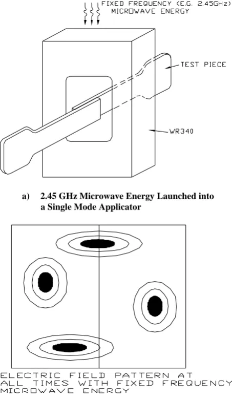
The VFM uses a TWT high power, broadband amplifier to sweep a range of frequencies of approximately an octave in bandwidth. The concept behind this approach is that continuous sweeping through several cavity modes within a period of a few microseconds, eg 20 μs results in time-averaged uniformity of heating throughout the load. The resulting relative heat distribution in a plane with fixed frequency (2.45 GHz) heating is not uniform as depicted in Figure 3. There is no mode control and hence the coupling efficiency is uncontrolled. There is limited potential for scaleup and high probability of hot spots and thermal runaway. On the other hand, the resulting relative heat distribution in a similar plane with VFM heating is uniform as shown in Figure 4 (Ku et al., 2000b). There is selective frequency control, high energy coupling efficiency, it is scalable to large processing volumes and there is uniform heating throughout (Lambda Technology, undated). An extra benefit of a VFM facility is that components with metal parts can be processed without causing arcing (Ku et al., 2000a).
Variable frequency microwave (VFM) processing is geared towards advanced materials processing and chemical synthesis. It offers rapid, uniform and selective heating over a large volume at a high energy coupling efficiency. This is accomplished using a preselected bandwidth sweeping around a central frequency employing frequency agile sources such as travelling wave tubes as the microwave power amplifier (Ku et al., 1999a; 2000a; 2000b; 2000c; Siu et al., 1999a; 1999b). Selective heating of complex samples and industrial scale-up are now viable. During VFM processing, a given frequency of microwaves would only be launched for less than one millisecond. In this research two variable frequency microwave facilities are used. One, Microcure 2100 Model 250 has a maximum power output of 250W generates microwave energy in the frequency range of 2 – 8 GHz and the other, Vari-Wave VW1500, operates at 6 – 18 GHz with a maximum power level of 125W. The cavity dimension of VW1500 was 250 mm x 250 mm x 300 mm; while, Microcure 2100 model 250 had a cavity size of 300 mm x 275 mm x 375 mm. The photos of these facilities are shown in Figures 5 and 6 respectively. Successful applications are in the areas of curing advanced polymeric encapsulants, thermoplastic matrix composite materials characterisation, adhesive characterisation, rapid processing of flip-chip (FC) underfills, joining reinforced thermoplastic matrix composites materials, and structural bonding of glass to plastic housing (Ku et al., 1999; 2000a; 2000b; 2000c; Siu et al., 2000; Siores et al., 20001; Anderson et al., 1998). It will be clear that there are a lot of factors that have to be considered before employing variable frequency microwave (VFM) irradiation for processing materials. Not all
materials are suitable for microwave processing and one has to match the special characteristics of the process to the materials. Blind applications of microwave energy in material processing will usually lead to disappointment. On the other hand, wise application of the technology will have greater benefits than has been anticipated.
a) 2.45 GHz Microwave Energy Launched into a Single Mode Applicator
[image:3.595.310.537.126.517.2]b) Electric Field Pattern for (a)
Figure 3: Fixed Frequency Microwave Heating – Nonuniform Heating
Previous successful applications of variable frequency microwave (VFM) ovens include the characterisation of glass or carbon fibre reinforced thermoplastic matrix composites, eg 33% by weight glass fibre reinforced low density polyethylene [LDPE/GF (33%)], of primers eg two-part five-minute rapid araldite (LRA), joining of the above mentioned composite materials with or without primer, and non-destructive testing and evaluation (Ku et al., 1999a; 2000a; 2000b; 2000cSiu et al., 1999a; 1999b).
4. Characterisation of Uniset Adhesive and Hysol Encapsulant
Sarawak, Malaysia,22-25 July 2002 © 2002 WEC
a) Variable Frequency Microwave Energy Launched into a Multi Mode Cavity
b) Electric Field Pattern at Different Times in (a)
Figure 4: Variable Frequency Microwave Heating – Time-Averaged Uniform Heating
VFM facilities were used to measure the characteristics of the cavity when a sample (epoxy in this case) was loaded. The procedure followed is a sequence of operations whereby the user graphically sees how the cavity, with material loaded, will operate over the selected frequency range. The input power is selected on the basis of the measured or sometimes estimated loss factor of the material (Ku et al., 1999b; 1999c). The higher the loss factor, the lower the power level selected because materials with higher loss factor will absorb more of the microwave energy and will convert it into heat. This will heat up the adhesives. If the input power is large and the loss factor of the material is high, the material will be dangerously over-heated and may set the VFM oven on fire. To control this, the temperature adjacent to the sample was monitored during the cavity characterisation process so that the machine could be switched off if a pre-set maximum temperature (100
o
C in this case) has been reached. During characterisation of the loaded cavity, temperature variations were obtained as well as incident power and reflected power levels from the cavity containing the sample; this information can also be known instantaneously to the operator via a monitor. The incident and reflected power levels versus frequencies together with the percentage of reflectance against frequencies were monitored and recorded.
Figure 5: Cavity of Vari-WaveVW 1500
Figure 6: Cavity of Microcure 2100 Model 250
5. Characterisation of the Epoxies from 6.5 GHz to 18 GHz
The total operation bandwidth for Vari-Wave VW1500 is from 6.5 GHz to 18 GHz. For the sake of keeping the temperature low, the characterisation bandwidth was broken into four equal sections. The reason for dividing the bandwidth into four sections was because the forward power, for a given setting, changed with respect to frequency, ie the amplified signal changed with respect to frequency. To minimise the error across the total operating bandwidth, the total band was therefore divided into smaller sections of roughly equal power, for a given power setting.
Sarawak, Malaysia,22-25 July 2002 © 2002 WEC
Figure 7: Percentage of Reflectance against Frequency for Uniset Epoxy in the Frequency Range of 6.5-18 GHz
[image:5.595.31.282.60.189.2]temperature setting, the input power was also 50 W and the amount of the epoxy used was also 5 mm3. The reflected energy ranged from 12.5W to 40W, ie 25% to 80% (Figure 8).
Figure 8: Percentage of Reflectance against Frequency for Hysol Encapsulant in the Frequency Range of 6.5-18 GHz
6. Characterisation of the Epoxies from 2 GHz to 8 GHz
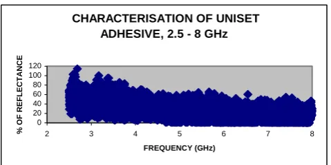
[image:5.595.313.553.76.196.2]This time the Microcure 2100 was used and the frequency range of the machine was from 2 – 8 GHz. The power level selected for both epoxies was 50W. The amount of epoxies used in both cases was 5 mm3. This was to ensure that the interaction of microwave energy and the sample was not too vigorous and that the facility could provide a complete sweep of frequency from 2 GHz to 8 GHz in a certain period of time without making the temperature in the cavity dangerously high. The temperature adjacent to the sample was monitored during the cavity characterisation process and the machine would be switched off once the temperature was over 100oC, which was not too far from the curing temperature of the adhesives. Figure 9 illustrates the percentage of reflectance against frequencies for Uniset adhesive. It was found that the percentage of reflectance was lowest in the frequency range of 6.5 GHz to 8 GHz. The percentage of reflectance ranged from 30% to 50%. Uniset adhesive was, therefore, best processed in this frequency range because it absorbed a greater proportion of the incident power. The best frequency ranges for the Hysol encapsulant was also found to be from 6.5 GHz to 8 GHz. The percentage of reflectance of the encapsulant was from 30% - 50%.
CHARACTERISATION OF UNISET EPOXY, 6.5 - 18 GHz 0 20 40 60 80 100
6 8 10 12 14 16 18
FREQUENCY (GHz)
% OF RE
FLE
CTANCE
CHARACTERISATION OF UNISET ADHESIVE, 2.5 - 8 GHz
0 20 40 60 80 100 120
2 3 4 5 6 7 8
FREQUENCY (GHz)
% O
F
REFLECTANCE
Figure 9: Percentage of Reflectance against Frequency for Uniset Epoxy in the Frequency Range of 2.5-8 GHz
7. Conclusion
The values of the percentage of power reflectance of the two epoxies in the frequency range of 2-8 GHz were higher than their counterparts in the frequency range of 6.5–18 GHz (Figures 7 through 10). This implies that the dielectric losses of these adhesives are higher at higher frequencies. By studying Figures 7 and 9, the lowest reflectance value for Uniset adhesive is 20% and is in the frequency range of 10–12 GHz. The best frequency range to process Uniset adhesive in the frequency range of 2.5 GHz to 18 GHz is thus from 10–12 GHz. Again by studying Figures 8 and 10, the lowest reflectance value for Hysol encapsulant is 25% and is in the frequency range of 10–12 GHz. The best frequency to process Hysol Encapsulant in the frequency range of 2.5–18 GHz is therefore 10-12 GHz. In conclusion, the best frequency range to cure the two epoxies in the frequency range of 2.5–18 GHz is therefore from 10–12 GHz. By performing materials characterisation, the best frequency range for microwave processing of a material can be discovered and followed by selective heating using variable frequency microwave sources. From the analysis of reflectance data of Figures 7 through 10, it can be deduced that Uniset adhesive is more ready to absorb microwave energy than Hysol encapsulant.
CHARACTERISATION OF HYSOL ADHESIVE, 6.5 - 18 GHz 0 20 40 60 80 100
6 8 10 12 14 16 18
FREQUENCY (GHz) % OF REF L E CT ANCE
CH ARAC TERISATIO N OF HYSOL EN CAPSULAN T, 2.5 - 8 GH z
0 20 40 60 80 100 120
2 3 4 5 6 7 8
FRE QUENCY (GHz)
% OF RE
FLE
CTANCE
Figure 10: Percentage of Reflectance against Frequency for Hysol Encapsulant in the Frequency Range of 2.5-8 GHz
[image:5.595.311.561.526.648.2]Sarawak, Malaysia,22-25 July 2002 © 2002 WEC
cavity is extremely complex and unpredictable (Ku et al., 1999a). Faced with such a complex situation, the best way to proceed is on a semi-empirical basis. To reduce the time consuming experimental empiricism that was required to develop relatively simple heating procedures, computer simulations of variable frequency heating may be employed (Bows, 1999; Dibben and Metaxas, 1999).
References
Amicon, Technical Data Sheet for Uniset adhesive A-312-20, pp. 1 (undated).
Anderson B, Ahmad I, Tucker D, Goldstein S, Fathi Z, Ramamoorthy A, Pal S and Mead P, Rapid Processing and Properties Evaluation of Flip-Chip Underfills, Proceedings of NEPCON West or http://www.microcure.com/papers.htm,
(username: vfmpapers; user password: microcure), pp.1–9 (1998).
Bible D W, Lauf R.J and Everleigh C A, Multi-kW Variable Frequency Microwave Furnace, Microwave Processing of Materials III, Materials Research Society, San Fransico, CA, (1992).
Bows J R, Variable Frequency Microwave Heating of Food, Journal of Microwave Power and Electromagnetic Energy, Vol.34, No.4, pp. 227-38 (1999).
Dexter, Technical Data Sheet for Hysol encapsulant EO 1060, pp. 1-2 (undated).
Dibben D C and Metaxas A C, Finite Element Time Domain Analysis of Multimode Applications Using Edge Elements, Journal of Microwave Power and Electromagnetic Energy, Vol.29, No.4, pp.242-51 (1999).
Fathi Z, Tucker D, Ahmad I, Yaeger E, Konarski M, Crane L and Heaton J, Innovative Curing of High Reliability Advanced Polymeric Encapsulants, Proceedings of NEPCON West, (1998).
Ku H S, Siores E, Ball J A R, Microwave Facilities for Welding Thermoplastic Composites, and Preliminary Results, Journal of Microwave Power and Electromagnetic Energy, Vol.34, No.4, pp. 195-205 (1999a).
Ku H S, Siores E, Ball J A R and Chan P, Complex Permittivity of Low Loss Thermoplastic Composites Using a Resonant Cavity Method, Proceedings of ICCM-12 in CD ROM, Theme: NDT & Reliability; Others, Paris, France, 5th - 9th July (1999b).
Ku H S, Siores E, Ball J A R and Chan P K H, Loss Tangent of Low Loss Thermoplastic Composites, Science and Engineering of Composite Materials, Vol.8, No.3, pp.123-7 (1999c).
Ku H S, Siores E, Ball J A R and MacRobert M, Characterisation of Thermoplastic Composites Using Variable Microwave Facilities Configuration, Plastics, Rubber and Composites, Vol.29, No.8, pp. 285-7 (2000a).
Ku H S, Siores E, Ball J A R and MacRobert M, Variable Frequency Microwave Processing of Thermoplastic Composites, Plastics, Rubber and Composites, Vol. 29, No.8, pp. 278-84 (2000b).
Ku H S, Siores E and Ball J A R, Relationship between Microwave Irradiation and Constituents of Composites during Joining Process, Transactions, The Hong Kong Institution of Engineers, Vol. 7, No.3, pp. 43-9 (2000c).
Lambda Technology Inc., What is Variable Frequency Microwave Processing? http://www.microcure.com, pp. 1-2 (undated).
Lauf R J, Bible D W, Johnson AC and Everleigh C A, 2-18 GHz Broadband Microwave Heating Systems, Microwave Journal, November, pp. 24-34 (1993).
Mair G, Mastering Manufacturing, the Macmillan Press Ltd., U.K., pp. 190-198 (1993).
Mackay A B, Tinga WR and Voss A G, Frequency Agile Sources for Microwave Ovens, Journal of Microwave Power, Vol. 14, No.1, pp. 63-76 (1979).
Metaxas A C and Meredith R J, Industrial Microwave Heating, Peter Peregrinus Ltd., pp. 5-6, 28-31, 43, 211, 217, 278, 284-5 (1983).
Siores E, Microwave Technology for Welding and Joining, Materials World, Vol.2, No.10, p. 526 (1994).
Siores E, Ku H S, Ball J A R and MacRobert M, Applications of Variable Frequency Microwave (VFM) On Adhesives, Journal of Adhesion Science and Technology, (accepted for publication) (2001).
Siu F, Siores E, Taube A and Blicblau A, Variable Frequency Microwave (VFM) for Non-Destructive Testing and Evaluation, J. ASME, Vol.234, No.17, pp.. 77-85 (1999a).
Siu F, Siores E, Taube A and Blicblau A, Non-Destructive Evaluation Using Variable Frequency Microwaves, J. American Institute of Physics, Vol. 497, pp. 63-8 (1999b).
Siu F, Ku H S, Siores E and Ball J A R, Variable Frequency Processing of Thermoplastic Composites, Proceedings of the Ninth International Manufacturing Conference in China (IMCC” 2000), Vol., 1, pp. 459-60 (2000).
Sutton W H, Microwave Processing of Ceramics, Ceramic Bulletin, Vol.68, No.2, pp. 376-86 (1989).
Wei J B, Ngo K, Tucker D A, Fathi Z, Paulauskas F L and Johanson W G, Industrial Processing Via Variable Frequency Microwaves Part I: Bonding Applications, Journal of Microwave Power and Electromagnetic Energy, Vol. 33, No. 1, pp. 10 – 17 (1998).
Sarawak, Malaysia,22-25 July 2002 © 2002 WEC