INTERNATIONAL CONFERENCE ON ENGINEERING DESIGN ICED 01 GLASGOW, AUGUST 21-23, 2001
INTELLIGENT COMPUTATIONAL SKETCHING SUPPORT FOR
CONCEPTUAL DESIGN
Sungwoo Lim, Alex H B Duffy, and Byungsuk Lee
Keywords: Computer-aided design, geometric modelling, probabilistic design
1 Introduction
Sketches, with their flexibility and suggestiveness, are in many ways ideal for expressing emerging design concepts. This can be seen from the fact that the process of representing early designs by free-hand drawings was used as far back as in the early 15th century [1]. On the other hand, CAD systems have become widely accepted as an essential design tool in recent years, not least because they provide a base on which design analysis can be carried out. Efficient transfer of sketches into a CAD representation, therefore, is a powerful addition to the designers’ armoury.
It has been pointed out by many that a pen-on-paper system is the best tool for sketching. One of the crucial requirements of a computer aided sketching system is its ability to recognise and interpret the elements of sketches. ‘Sketch recognition’, as it has come to be known, has been widely studied by people working in such fields: as artificial intelligence to human-computer interaction and robotic vision. There are three main issues in adopting sketch recognition for supporting conceptual design activities:
• Sketch capture: Conversion of a bitmap sketch to a computational model through a sketch recognition technique is an important task, currently most relevant to the detailed design stage, and is still a major research issue. During this process all the vagueness contained in the original sketch is removed.
• Interpretation of the sketch structure/content: It is not always easy to interpret the meaning of a sketch correctly, even for example such a basic attribution of 2D or 3D. The confusion between 2D and 3D often occurs from misunderstanding the structure of the sketch.
• Capturing the intended meaning: One sketch stroke can have different intended meanings such as a geometric shape or abstract idea. In the case of a geometric shape, a sketch can only be meaningful in the sense of 2D or 3D geometry. However, in the case of an abstract idea, it could be a symbol, character, functional relationship between entities, concept or idea, i.e., in this case a sketch may have a meaning beyond the simple geometry represented by the sketch strokes.
2 Existing Approaches to Conceptual Design Support
Considerable work has been done to solve various problems encountered in trying to give computational support of design sketching activities (see Table 1). These efforts can be classified into three main areas: geometric modelling, spatial arrangement and design environment support as follows.
Table 1. Summary of various approaches [2] – see references for comments
Area Sub-Area Functionality Technology Works
2-Dimensional Sketching
• Automatic line tidy
• Symbol recognition
• Pre-processing / processing
• Fuzzification/fuzzy filter Easel, FFDS, Electronic Cocktail Napkin. 3-Dimensional Sketching
• Automatic surface creation
• 3D sketching environment
• Geometric model structure analysis
• Image processing
• Sketch interpreter
• Direct-manipulation interaction
• Sketch interpretation
Akeo, Lipson, HoloSketch, SKETCH, Viking, ISO-Sketcher. G eom et ri c M ode ll ing Sketch recognition
• Symbol/diagram recognition
• Hidden line (re)construction
• Image retrieval by diagram
• Low level recogniser
• Soft constraint
• Perceptual analysis
Lamb, IDeS, Electronic Cocktail Napkin, Quick-Sketch. Spatial (Re) arrangement and analysis
• Spatial layout analysis • Goal object(GOB)
• Constrained heuristic search
• Similarity of spatial pattern LOOS, SPIDA, ABLOOS, THESYS, WRIGHT. S pa ti al A rra n g em ent Vague spatial relationship modelling
• Location constraints
• Uncertain region
• Vague spatial
relationship modelling
GEMCON.
GUI builder by sketching
• Interface programming without coding
• Storyboard mechanism SILK.
Past design retrieval by sketching
• Retrieval by partial design elements
• Retrieval by image
• Case based reasoning
• Object-oriented programming Archie-II, A.S.A. D es ign E nvi ronm ent S upport Front-end system
• Universal modelling interface
• Vague geometric modeller
ARCHPLAN, ISO-Sketcher.
2.1 Geometric Modelling
[image:2.595.74.534.189.599.2]2.2 Spatial Arrangement
Spatial arrangement is concerned with the modelling and analysis of the spatial relationships of geometric models. Guan [3] points out that this approach usually deals with the problem of physical arrangement of objects and spaces to fulfil the needs of various human activities, based on a variety of explicitly or implicitly defined requirements and criteria that usually conflict with one another. This problem is common in many areas, including architectural and mechanical design. The essential issues addressed in this area of work are analysis and modelling based on spatial relationships between geometric models. Most systems attempt to model 2D spatial layout within their specific requirements using techniques such as numerical constraints. Despite the stated aim of supporting the conceptual design activities, most work in the area of spatial arrangement does not serve the purpose particularly well. Most systems feature automatic decision-making techniques in interpreting the geometric information and this alone is insufficient. They tend to concentrate on representing the spatial relationships between 2D rectangular shapes, apart from Kameyama et al. [4] that supports 3D spatial layout. On the other hand, a few systems support vague spatial relationships that can occur in rough geometric sketches. WRIGHT and GEMCON adopted some inequality types (including
=, <, ≤, >, ≥, ≈, [, ]) and linguistic values (including above, below, front, behind, left, right). Thus it is possible to consider relations between design units that do not have fixed locations or fixed dimensions. However, both systems suffer from their inability to be more specific; for example, if A > B, by how much.
2.3 Design Environment Support
A number of systems have been developed to support the environment of geometric modelling serving diverse purposes. SILK allows designers to sketch quickly a user interface using an electronic stylus. It recognises 2D sketched shapes and turns these into an active user interface without re-implementation or programming. It also provides a “storyboard” mechanism to test subjects to evaluate the interface in its early, sketchy state. Some serve as a case browser, emphasising presentation of information to users over adaptation or application of past solutions. Yet others were developed to implement a front-end system. For example, ARCHPLAN explores the usefulness of object-oriented programming techniques to support the abstractions of the design process and the resulting design solution. ISO-Sketcher supports an autonomous pseudo-3D sketching environment, linked at run-time to an underlying geometric modeller, GEMCON. ISO-Sketcher is said to offer the early-stage geometry designer an environment supporting a minimum commitment approach, in which the designer is not compelled to make any commitments as to size, location or spatial relationships until desired. However, the system can only deal with the spatial arrangement of vague objects within a limited space and does not provide any effective means to model and manage vague geometric information.
3 Vague Geometric Modelling
of shapes that agree with such an incomplete specification to a greater or lesser extent. Lipson et al. [6] points out the necessity of incorporating analysis tools in conceptual design. Lim et al. [7] proposed “the necessity and methods of the representation and maintenance of vague geometric ideas to support characteristics of conceptual design stage”.
In this paper, the word vagueness is defined as “the uncertainty about meaning” [8] which “can be represented by a probability distribution over possible meanings”. The uncertainty should be modelled in a form which allows the (re)utilisation of the information [8]. To allow a (re)utilisation of the uncertainty, a vague geometric model should include the entire possible range of vague types or values. Based on the definitions of vagueness, a Vague Geometric Model (VGM) can be defined as ‘a geometric model which implicates ill-defined abstractions, numerical values and/or spatial information’. Furthermore, Vague Geometric Modelling (VGMing) can be defined as ‘a modelling method that can represent and maintain the vague information contained in a VGM’.
Deliberate preservation and handling of vague information is a non-trivial task and represents a departure from current approaches used in sketch recognition. Preserving the vagueness will undoubtedly call for new techniques to represent and model the vague information, which, in our case, is mostly geometrical. It is also in accordance with the principle of minimum commitment, that is, in keeping as many options open for as long as possible. Consequently, a new approach is required for an effective VGMing technique that can represent vague information. To represent vague information of a shape, we suggest that the following functions should be satisfied.
• Alternatives by multiple probabilities of each element: A sketch stroke can represent multiple alternatives, such as a straight line, curve, or even geometric shape. Hence, the shape type of an object can be changed by a choice of alternatives within each child-element (in this paper, the term ‘child-child-element’ is used to explain the hierarchical sub-class of a shape element which could be a rough sketch stroke). This means that the probability of a vague shape can be different depending upon which alternative child-element is chosen. Keeping all the possibilities like this is helpful for discovering hidden features in a representation without being fixated to a single perspective (see [9]). These unexpected discoveries could be more easily found in the original rough sketch when the original ideas are maintained without any refinement (see also [2, 5]).
• Combination of probabilities of child-elements in a hierarchical structure: Biederman [10] argued that a set of ‘geons’ (geometrical ions) can represent a wide range of shape variations. According to his proposal, single geons correspond to elementary shapes (e.g. cylinders, curved cylinders, and bricks) and all shapes can be represented by a combination of geons. As Kavakli [11] argues a significant proportion of drawn parts, whether from memory, imagination or by over-tracing, are produced part by part, which implies that most sketching activities are done by drawing parts of an object. Since an object is drawn by the combination of the parts, a hierarchical structure of these parts could be one way of representation that can be used for VGMing. This allows a clearer understanding of the nature of the vague element, and makes it easier to show a combination of vagueness that could be represented as probabilities (see Figure 1). With this structure, therefore, possible alternative interpretations of the element, object and the sketch as a whole can be made more visible [2].
the idea of sorting similar things into categories is clearly a primitive one since classification, in the widest sense, is needed for the development of language. Language consists of some words which help us recognise and communicate the different types of events, objects and people. In order to perform clustering, appropriate criteria are needed. Vague shapes may also be clustered differently depending on different viewpoints [13]. As some researchers [9, 13-15] argued, this kind of vagueness happens frequently when the designer and the user are different. In addition, the criteria could be more abstractly specified if the type of the object (i.e. design concept) is predefined.
has-part
• Has-part relations are employed to link concepts of the type from more general levels to more detailed levels with respect to the whole design.
• Has-kind relations are employed to link concepts of the type from higher abstraction levels to lower abstraction levels.
has-kind Classification hierarchy Object hierarchy
(n)th Elemen Object
Object Object
1st
Element 2nd
Element
(n-1)th Element
(n)th Element Object
3rd Level 2nd Level
1st Level
…………
…………
…………
10%
Polygon
3% 17% 35% 45% 70%
30% 63%
27%
64% 36%
Element(n) : A sketch stroke
Object : An Object which involves multiple elements : Highest probability path
Composite-Ellipse- Straight- Arc-
………… Pentagon Rectangle Triangle Free curve Ellipse Circle
Polygon Closed curve Curve Straight line
Closed shape Open shape
Figure 1. Hierarchical structure of vague information [2]
4 Prototype System
A prototype system, I-MAGI, is currently under development using Macintosh Common Lisp (MCL) 4.0 running under MacOS 8.6. The details of the prototype system process are as follows. Detailed methods are described in [2], thus, only a brief overview is presented here.
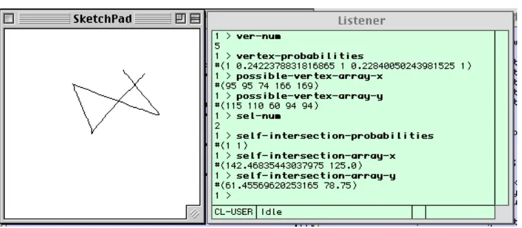
[image:5.595.74.527.184.540.2]• Pre-processor: Each new stroke entered is first sent to the pre-processor, which initially identifies the potential vertices and self-intersection points. These points are given probabilities of being vertices of a polygon according to their spatial relationships with the neighbouring points of the stroke. First, each connected four line segments, which are created by the five original points, are sequentially analysed (we use the term line-unit to denote these bunch of line segments, Figure 2). A line-unit is used to identify the probability of the third point of each line-unit. Basically, the pre-processor identifies all the potential vertices and intersection points apart from unintentional vertices because of a designer’s hand vibration (i.e. hand shaking). The pre-processor checks the type of one line-unit, and if the shape type of line-unit is ‘\/\/’ or ‘_/\_’, then it is not considered as potential vertices. Second, the pre-processor checks each pair of line segments in a stroke respectively to find the intersection points (see Figure 3). Figure 4 shows an example of possible vertices and self-intersection points with associated probabilities. The initial numbers of vertex (ver-num) and self-intersection (sel-num), (x, y) coordinates, and probabilities are identified.
• Processor: The above vertex probability information is then sent stroke by stroke to the processor, which analyses the probabilities of each stroke representing the primitive elements which are pre-defined by the system (see the primitive elements of third hierarchical level in Figure 1).
• Post-processor: When the designer has defined one object containing a number of strokes, these processed strokes and the probabilities are sent to the post-processor which carries out the three tasks sequentially. Firstly, the size of the input object is now expanded as 3D co-ordinates if applicable. Second, the vague relative spatial relationship is analysed by the combination of distance and direction when there are more than two objects. Third, the VGM, which is created through the process, is clustered by customised viewpoints.
• Output: Finally, the designer gets a VGM and various alternatives associated with vague information.
Figure 2. (a) Sequential capturing of the line-unit, and the third point of the line-unit. (b) The exception to identify the potential vertices
(b) (a)
• •
• • • •
Sequential line-unit
• •
• •
•
A sketch stroke •
• • • • • •
•
4
• • • •
•
3
• • •
•
2
• •
•
1
•
Third point of the line-unit
•
stroke
Case 2: _/\_ Case 1: \/\/
• • • • •
[image:6.595.79.516.487.645.2]n: Total number of point in the stroke (i.e., n = 6). Lij: Line segment between i and j.
•
6•
5•
4•
3
•
2•
1for i = 1 to n
for j = (i + 1) to n
Find-intersection (Li(i + 1), Lj(j +1))
end
end
Figure 3. General algorithm to find intersection point
Figure 4. The probabilities of the vertices and intersection points from the sample stroke
5 Conclusion
Visualisation of conceptual models, in the form of sketches, is important for a more flexible and dynamic design. Sketches often play an important role in concept generation in design. Consequently, to capture, model and more fully utilise these concepts we need to integrate the sketching activities into the CAD environment. Much work to date on sketch recognition and computer-aided sketching systems support the need to provide computational based sketching. However, current approaches do not offer any method of representing and managing vague information often found in conceptual ideas as reflected in sketches.
In this paper, the existing approaches and representative works with sketching to conceptual design have been reviewed. A possible approach to vague geometric modelling based on a hierarchical structure and probabilistic method, and their associated issues have been discussed with the prototype system I-MAGI. The new approach will support minimum commitment by: a) modelling of vague shape itself; and b) maintaining the vagueness relating to the interpretation of shape rather than fixing upon a particular shape.
[image:7.595.126.462.78.224.2] [image:7.595.110.489.249.415.2]References
[1] Jenkins, D.L. and R.R. Martin, "The importance of free-hand sketching in conceptual design: automatic sketch input", American society of mechanical division, 53: 1993, p115-128
[2] Lim, S., B.S. Lee, and A. Duffy, "Incremental modelling of ambiguous geometric ideas (I-MAGI)", Special Issue on Conceptual Modeling in Design Computing of the International Journal of Artificial Intelligence in Engineering, 2001. (to be published) [3] Guan, X., "Computational support for early geometric design", in CAD centre, Dept. of
DMEM, Strathclyde University, Glasgow, 1994, p275
[4] Kameyama, K.-I., K. Kondo, and K. Ohtomi, "An Intelligence layout CAD system for industrial plants", Design Theory and Methodology (DTM'90), 1990
[5] Martin, R.R., "Modelling inexact shapes with fuzzy sets: Fuzzy-Set-theoretic Solid Modelling", in Proceedings CSG'94, 1994
[6] Lipson, H., "An interface for 3D conceptual design based on freehand sketching", IFIP WG5.2 Workshop on Geometric modeling in Computer Aided Design, 1996
[7] Lim, S., A. Duffy, and B. Lee, "Incremental Modelling of Ambiguous Geometric ideas (I-MAGI)", Advances in Conceptual Modeling in Design, AID00, 2000
[8] Cheeseman, P., "Probabilistic versus fuzzy reasoning", Uncertainty in artificial intelligence, 1986, p85-102
[9] Suwa, M., J. Gero, and T. Purcell. "Unexpected discoveries: How designers discover hidden features in sketches", Visual and Spatial Reasoning in Design, 1999
[10] Biederman, I., "Recognition-by-components: A theory of human image understanding", Psychological review, 94: 1987, p115-147
[11] Kavakli, M., S.A.R. Scrivener, and L.J. Ball, "Structure in idea sketching behaviour", Design Studies, 19(4): 1998, p485-518
[12] Everitt, B.S., "Cluster Analysis: Third Edition", 1993
[13] Duffy, A.H.B. and S.M. Kerr, "Customised Perspectives of past designs from automated group rationalisations", International Journal of Artificial Intelligence in Engineering, Special Issue on Machine Learning in Design, 8(3): 1993, p183-200
[14] Fisher, D., L. Xu, and N. Zard. "Ordering effects in clustering", In Proceedings of the Ninth International Conference on Machine Learning, 1992
[15] Howard-Jones, P.A., "The variation of ideational productivity over short timescales and the influence of an instructional strategy to defocus attention", in Proceedings of Twentieth Annual Meeting of the Cognitive Science Society, 1998.
S W Lim
![Table 1. Summary of various approaches [2] – see references for comments](https://thumb-us.123doks.com/thumbv2/123dok_us/1732002.126656/2.595.74.534.189.599/table-summary-various-approaches-references-comments.webp)
![Figure 1. Hierarchical structure of vague information [2]](https://thumb-us.123doks.com/thumbv2/123dok_us/1732002.126656/5.595.74.527.184.540/figure-hierarchical-structure-vague-information.webp)