INTEGRATION OF BUILDING SIMULATION INTO THE DESIGN PROCESS OF AN ARCHITECTURE PRACTICE
Christoph Morbitzer
*, Paul Strachan
#,
Jim Webster
*, Brian Spires
*, David Cafferty
**
HLM Design Ltd, Glasgow, G1 4JH, United Kingdom, email [email protected] #
Energy Systems Research Unit (ESRU), University of Strathclyde, Glasgow, G1 1XJ, United Kingdom, email: [email protected]
ABSTRACT
A key barrier to the acceptance of simulation within building design has been identified as the fact that it is not fully integrated into the design process. The project described in this paper attempts to address this barrier by embedding modelling as a standard component of design practice procedures within an architectural practice.
Important elements of the research that are described in the paper are:
• identifying the role building simulation can play at the different stages of design;
• developing a model description that evolves through the design process as the building design becomes more highly specified;
• simplifying the user interface at the early stage of the design where rapid feedback is required and where most impact can be made on the building’s energy and environmental performance;
• customising results presentation to be appropriate for the particular stage of design; and
• implementing these simulation concepts, observing their acceptability, and addressing quality assurance and training issues.
Key words: Building design practice, outline design stage.
INTRODUCTION
Over the last two decades, the development of dynamic building simulation programs has resulted in high levels of modelling capability. This enables simulation experts to provide building designers with quality information in areas where they previously had to rely on experience, use simplified calculation methods or apply rules of thumb.
However, building simulation programs are not recognised as design support tools to the same extent as CAD tools or costing software. Evidence for poor uptake of the technology by industry can be found in the literature (Andre at al. 1994, Bauer et al. 1998, De Wilde et al. 1998, Robinson 1995, Hien et al 2000) and in the fact that, for example, the International Conference on Construction Information Technology 2000 (Reykjavik, Iceland) contained only one paper on dynamic building simulation but a number of papers on Virtual Reality in Construction. This conclusion was also confirmed by visits to a number of typical building design practices.
Lawson (1990) points out that building design has moved from a ‘craft-based approach’ to a process that involves advanced technologies and inherits endless difficulties. This can be linked to the view that simulation should not be used only for final performance confirmation but as an integrated element of the design process (Augenbroe 1992, Holm 1993, Mahdavi 1993). BMBF (1998) and McElroy (1999) point out that the simulations should actually be performed within the design practice. As a result it was decided to undertake a comprehensive analysis of the building design process with an emphasis on several questions:
• Which are key performance studies to be undertaken at the various building design stages?
• What software is best adapted to the experience and background of the typical user at the different design stages?
• How can simulation results be displayed in a way that turns the raw data into useful quality information?
After a brief presentation of the project background, this paper describes the suggested performance studies at the different design stages and then a software concept that was developed for the first
Seventh International IBPSA Conference
Rio de Janeiro, Brazil August 13-15, 2001 Integration of Building Simulation into the Design Process of an Architecture Practice
Integration 1
building design stage (Outline Design Stage). Results presentation, and other practical issues such as the need for training and quality assurance procedures are also discussed.
PROJECT BACKGROUND
The research was undertaken as part of a TCS project, a major UK government initiative to facilitate the transfer of technology and the spread of technical skills from universities to industry. The industrial partner of the programme is HLM Design Ltd, a progressive architectural practice in the UK. HLM provided the testbed that was essential for the conduct of the research project.
HLM Design Ltd recently took the decision to adopt building performance modelling as part of the everyday design process. The company has offices in Glasgow, Sheffield and London. Their ultimate aim is to include thermal, lighting and cost analysis methods as an integral part of their design practices. The practice has launched a two year TCS program in partnership with the University of Strathclyde, with the aim of developing an in-house simulation capability.
SIMULATION IN THE DESIGN PROCESS
To establish a holistic design approach with simulation having an input at all stages it was necessary to determine the design approach of the architecture practice used as a test bed. The approach developed was also compared with related approaches in the published literature.
The RIBA design plan of work (RIBA 1995) identifies three main building design stages:
• Outline Design Stage
• Scheme Design Stage
• Detailed Design Stage
Different design objectives and scopes can be observed in the different building design stages. The aim was to identify for the different stages key parameters that are part of the designer’s consideration, which will have a significant influence on the energy and environmental performance of the building and hence which should be included in simulation studies.
The parameters selected either did not increase the building cost or had reasonable payback periods. Hence the list does not, for example, include photovoltaic systems but does consider chilled construction systems.
The following section covers, for each design stage:
• A short description summarising the RIBA definition of different building design stages.
• Comments on how simulation can provide additional design support.
• Key elements required to successfully integrate simulation into the design process.
Outline Design Stage
In this design stage a concept based on feasibility studies is prepared. It shows the design analysis and options considered, and will be sufficiently detailed to establish the outline proposal preferred. It can include diagrammatic analysis of the requirements on the site, solutions to functional and circulation problems, relationships of spaces, massing, construction and environmental methods and a cost appraisal to enable an approximation of construction cost. This design stage is extremely time constrained. The designer will be interested in an indication of the energy consumption that can be expected from the building. Simulation can also point out problem areas, identify parameters that cause the problem and assess the scale of the problem.
In general it is important to enable the user to understand quickly how the building shape, glazing areas, proposed room functions and construction types will affect the environmental performance of the building.
Scheme Design Stage
The Outline Design Stage proposal approved by the client is now taken to a more detailed level. Tangible material produced can include site layout, planning and spatial arrangements, elevation treatment, construction and environmental systems.
Simulation will focus on problem areas or on typical building sections. In terms of environmental simulation this stage can be seen as a ‘load reduction stage’, with the designer having more time available to spend on certain issues. Simulation parameters also relate more to the building envelope (glazing properties, ventilation rates).
Detailed Design Stage
Now the approved Scheme Design solution is worked through in detail. Detailed design drawings are produced for co-ordinating structure, services and specialist installation. Internal spaces may be detailed to include fittings, equipment and finishes.
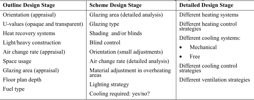
Table 1: Parameters evaluated at the different building design stages
Outline Design Stage Scheme Design Stage Detailed Design Stage
Orientation (appraisal)
U-values (opaque and transparent) Heat recovery systems
Light/heavy construction Air change rate (appraisal) Space usage
Glazing area (appraisal) Floor plan depth Fuel type
Glazing area (detailed analysis) Glazing type
Shading and/or blinds Blind control
Orientation (small adjustments) Air change rate (detailed analysis) Material adjustment in overheating areas
Lighting strategy Cooling required: yes/no?
Different heating systems Different heating control strategies
Different cooling systems:
• Mechanical
• Free
Different cooling control strategies
Different ventilation strategies
purposes such as designing a natural ventilation strategy (sizing of openings, establishing control strategies, confirming minimum and maximum air flow) or to model other building services applications such as chilled construction systems or air conditioning systems.
Table 1 summarises parameters that were identified for the different design stages. The CIBSE Guide for energy efficient building design (CIBSE 1998) identifies for the different design stages a good practice strategy for the timing of design decisions to ensure energy efficient building design. These design decisions show good agreement with the proposed simulation strategy at the various design stages as summarised in Table 1. This gives confidence into the outcome of the research that was undertaken.
The following is an example of the design decisions taken at the various stages of the design process. In the case of an overheating problem, simulation would provide the following key inputs at the various design stages:
• Outline Design Stage - point out the overheating problem to the designer, identify causes of the problem and assess its scale.
• Scheme Design Stage - evaluate the issue in detail and try to reduce it by consideration of additional design parameters (shading and blinds, advanced glazing, ventilation rates).
• Detailed Design Stage – use simulation to establish with detailed air flow modelling a ventilation strategy that fulfils the previously established ventilation requirements.
THE CONCEPT FOR THE OUTLINE DESIGN STAGE
The general concept of the approach can be seen in Figure 1. The intention was that the same advanced simulation engine (ESP-r, ESRU 2001) will be used throughout the design process, but with interfaces, software functionality, defaults and results analysis tailored to the requirements of all three design stages.
Using the same simulation tool throughout the design process has additional advantages:
• It is possible to pass a model directly from one design stage to the next one.
• Concepts in model creation and results analysis are similar. This provides different user groups with a common background and makes it easier to tackle environmental issues in a holistic approach that does not separate the different parties and design stages.
Interface Design
During the research it became clear that it is not advisable to develop a single simulation program interface that can be used throughout the design process. A flexible interface, matched to the various design stages, should be developed.
There are a number of reasons for this:
Figure 1: The simulation approach
with additional knowledge in environmental building design will use the tool for a quick evaluation of a design concept. At the Scheme and Detailed Design Stage it will generally be simulation specialists using the tool1.
• Different issues get addressed at the different design stages. Being able to access all possible design parameters at the Outline Design Stage would overcomplicate model definition, especially for less experienced users. The designer should see environmental modelling tools as an additional useful support. Complex tools will cause reservations among potential users.
• Different users need to be presented with the results in different ways. Specialists will want an in depth understanding, less experienced users will want to get a quick evaluation in terms of model performance and (especially if there are problems) reasons for this performance.
The following sections focus on the Outline Design Stage. There are a number of benefits derived from
1
However, a valuable future improvement would be experienced architects performing the simulation since at the Scheme Design Stage since the parameters to be assessed, such as inclusion of blinds, shading elements or tinted windows, have significant architectural implications
emphasising this design stage. At this time, decisions are made which have important implications on the energy consumption and comfort conditions in the building. Pointing out these effects to the designers can significantly influence their advance towards an appropriate design solution. This, on the other hand, is not an easy task: The design stage is extremely time constrained, the typical user has limited experience in simulation and environmental issues, and important building parameters affecting thermal performance have often not yet been specified.
Model Creation
A number of key developments are part of the user Outline Design Stage (ODS) Interface:
• The program interface is structured to permit a step-by-step, rapid input procedure for the base case model and design options.
• 3D CAD software is used to define the model geometry.
Figure 2: Flow chart of the ODS Interface software structure
The Outline Design Stage (ODS) has a logical, step-by-step input procedure. Figure 2 gives an overview of the overall structure.
Rapid input procedures such as global model attribution for constructions are a key software design element to address the time constraints described above. For such automated attribution, it is necessary to know the construction properties such as their tilt and whether they are internal or external. As CAD drawings do not specifically provide this information, the ODS Interface has to retrieve it in a background process when importing the geometry definition. After global attribution the user has still the possibility of local changes.
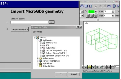
CAD Link
The ODS Interface uses a CAD tool for its geometry definition. Figure 3 depicts a geometry import. The CAD link has important implications:
• Rapid geometry definition can be achieved efficiently via a link to a CAD tool.
• It is possible to use existing architectural drawings to create the geometry definition of the thermal model. This will reduce input error risks and time requirements.
support tool. It has to be pointed out that this link is so far only possible with one CAD tool, but that the ODS Interface can also import drawings from a number of other CAD package.
Figure 3: Import of CAD Geometry
Templates and Defaults
An aim of the design of the ODS Interface was to allow model definition to be as accurate as possible without overcomplicating input issues for the user. For this purpose support database structures were developed and extensively populated using guidelines and tables that are well accepted in the construction industry. The zone type definition is used here to describe the concept:
The user selects, for every zone, its usage function (which affects internal heat gains, ventilation requirements and possible heating and ventilation/cooling schemes), location in the building (which affects possible ventilation/cooling schemes) and finally the ventilation/cooling scheme. The user has visual control over selection and can focus this control on different seasons and day types.
Figure 4: Definition of Room Function
The program then automatically populates the building model with detailed hourly ventilation, control and internal heat gain profiles.
Database Structure
The ODS Interface was developed using a database structure in which different simulation model, project and design option components are decomposed and saved as database tables. Tables vary from default construction and room function datasets (general software level) through surface and zone properties (project level) to design option data and results data. This makes it possible to populate the project-related tables with data from generic tables (defaults) and to copy, save and recover from design option tables. It is also possible to easily define and control user access, both in terms of data admission (project level, design option level, support databases) and data access level (view, edit, add).
The database/decomposition approach also allows all the information to be saved in one central database, which is accessible from company offices in different locations. For big companies it could be expanded to a Web-based application. All this is possible while still maintaining control over data access and data changes.
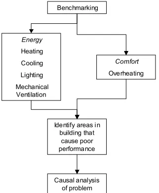
Results Analysis
Presentation of performance data is another vital element of building simulation interface design. It is important to turn the raw data obtained into quality information. Developing presentation formats for predicted performance is a far from trivial task (Donn 1997, Mahdavi 1998, Soebarto et al. 1999). The results analysis approach developed in this project attempts to provide a structured presentation of building energy and environmental performance, along similar lines to other recent support tools such as BDA (LBNL) and Energy10 (NREL).
The guided results analysis for each Design Option starts at a high level but with the possibility for presenting more detailed, explanatory data as necessary. This includes the following key components:
• Ranking of the results against benchmarks. This should help the designer to judge the environmental performance of the design and point out potential problems in the building.
• Identifying areas in the building that case poor performance.
• Identification of the reasons for unsatisfactory performance.
0 5 10 15 20 25 30
1 3 5 7 9 11 13 15 17 19 21 23
0 1 2 3 4 5 6 7
1 3 5 7 9 11 13 15 17 19 21 23 0 10 20 30 40 50 60 70 80 90 100
[image:6.595.72.290.527.687.2]After performing the simulation, hourly result data is read into the database structure. The software then determines annual energy figures and compares them against benchmarks. The query function of the database then also allows an interactive interrogation of the result set:
• Filter the main energy consumers in the building.
• View the energy flows in the building depending on, for example, time of day, external temperature, occupancy, only certain zone(s) etc..
[image:7.595.95.256.375.570.2]Energy flows in heating periods are displayed as heat gains and losses of the building. For the summer cooling period, thermal comfort is the most important performance criterion. Information on comfort levels and overheating hours are presented, together with cooling loads in the case of air-conditioned buildings. The user can also determine the main causal factors of the predicted performance. The feedback given to the user should help in developing further design options.
Figure 5 shows the concept how to analyse one Project Design Option.
Figure 5: Structured results analysis The software allows in addition to the analysis of each Design Option also a performance comparison of different design options by comparing their overall energy consumption.
OTHER ISSUES - TRAINING AND QA
For successful assimilation of simulation software into design practice, training of staff is required. This requires knowledge of the capabilities of simulation by all the design team, and specific
application knowledge by some staff members. At HLM this is done in two ways:
• Training a small number of staff in each office in thermal modelling. The training includes practical experience in program use, but also an introduction to basic concepts of thermal modelling (zoning, ventilation schemes) and results analysis.
• An on-line presentation on the office intranet outlining concepts and potential of thermal modelling. This raises the general awareness of the software and helps to identify additional members of staff that are interested in using the software.
Simulation is used in a very time constrained situation and can also have a significant impact on the decision making process. This makes it vital to ensure quality information. For this purpose, quality assurance (QA) procedures are very important. The company is currently developing QA procedures that involve training, peer review of models and pragmatic assessment of results. It is the intention that these will be included in the company procedures and subsequently an established part of the design process.
CONCLUSIONS
This paper has described a project currently in progress that has the objective of embedding simulation as a dedicated studio resource within an architectural practice, thereby making simulation an integrated component of the design process. Key elements and findings of the research are:
• Building simulation is currently not an integrated element of the design process. However, because of the complexity of the design process and the advanced technologies now applied in the building industry this would be very desirable. Integrating modelling would raise awareness of energy and environmental issues and give it an adequate status in design decision making.
• Different design objectives and scopes can be observed in the different building design stages. Research was undertaken to identify for each design stage key parameters pertaining to energy and environmental performance that could be addressed by simulation.
• The concept developed is based on the use of one simulation program throughout the design process to ensure continuity between the different design stages.
Energy
Heating
Cooling
Lighting
Mechanical Ventilation
Identify areas i n building that
cause poor performance
Causal analysis of problem
Comfort
• Although there are merits in using a single simulation program, it was found necessary to develop different user interfaces for the different design stages. The interfaces need to reflect typical simulation issues related to the particular design stage and the expertise and background of the user. An example was shown of an interface that has been developed for the Outline Design Stage.
• Effective results presentation is a key element of the use of building simulation software. Hence the results analysis should again be customised to the different design stages. Detailed information can be confusing for occasional users but vital for the expert user.
ACKNOWLEDGEMENT
Scottish Energy Systems Group (SESG) for access to knowledge, techniques and tools for the
deployment of simulation based technologies.
www.sesg.strath.ac.uk
Jan Hensen for valuable ideas related to the deployment of simulation in design.
REFERENCES
Andre P, Nicolas J, “Use of an integrated software system for building design
and system simulation”, Proceedings of the Conference of Systems Simulation
in Buildings, Liege, Belgium, 1994
Augenbroe G, “Integrated building performance evaluation in the early design
stages”, Building and Environment, Building and Environment, Vol.27, No. 2,
pp 149-161, 1992
Baker N V, Steemers K, “The LT Method, Version 2 – An energy support tool
for non-domestic buildings” (The TL method was developed by the Martin
Centre for Architectural and Urban Studies, Cambridge and is available from
the Royal Institute of British Architects, RIBA)
Bauer M, Haller R, Sucic D, “Optima – A software tool generating building
models for simulation tools from CAD drawings”, Proceedings of the
Conference of Systems Simulation in Buildings, Liege, Belgium, 1998
Bax T, Trum H, Nauta D, “Implications of the philosophy of Ch. S. Peirce for
interdisciplinary design”, Proceedings of the 5th International Conference on
Design and Decision Support Systems in Architecture, Eindhoven, pp 25-46,
2000
BMBF (Bundesministerium für Bildung, Wissenschaft, Forschung und
Technologie), “Förderkonzept ‘Solar otimiertes Bauen’ – Informationen zum
Teilkonzept 3: Solar Optimierte Gebäude mit minimalem Energiebedarf”, 1998
CIBSE (Chartered Institute of Building Services Engineering), “Energy
efficiency in Buildings”, CIBSE Publication, p 2-5, 1998
Clarke J A, Hand J W, Mac Randal D F, Strachan P, “Final report for the
COMBINE Project“, University of Strathclyde, 1995
De Wilde P, Van der Voorden M, Augenbroe G, “Towards a strategy for the
use of simulation tools as support instrument in building design”, Proceedings
of the Conference of Systems Simulation in Buildings, Liege, Belgium, 1998
Donn M R, “A survey of users of thermal simulation programs”, pp 65-72,
Proceedings of the 5th IBPSA Conference (Building Simulation 97), Prague, pp
65-72, 1997
ESRU, “ESP-r: A Building and Plant Energy Simulation Environment: User
Guide Version 9 Series”, University of Strathclyde, Glasgow, 2001.
Holm D, “Building thermal analysis: What the industry needs: The architectural
perspective” Building and Environment, Building and Environment, Vol.28,
No. 4, pp 405-407, 1993
Lawson B, “How designers think – The design process demystified”,
Butterworth Architecture, pp 15-17, 1990
LBNL (Lawrence Berkley National Laboratory), “Building Design Adviser
Homepage”, http://kmp.lbl.gov/BDA
Mahdavi A, “Simulation-based performance evaluation as a design decision
support strategy: Experiences with the ‘intelligent workplace’”, Proceedings of
the 3rd IBPSA Conference (Building Simulation 93), Adelaide, pp 185-191,
1993
Mahdavi A, Akin, Ö, Zhang Y, “Formalization of concurrent performance
requirements in building problem composition”, Proceedings of the 4th
International Conference on Design and Decision Support Systems in
Architecture, Eindhoven , 1998
McElroy L, Clarke JA, “Embedding simulation within energy sector business”,
Proceedings of the 6th IBPSA Conference (Building Simulation 99), Kyoto, pp
262-268, 1999
Cambridge Data Systems Ltd, MicroGDS 6.0 - 3D Modelling and Rendering
(user manual)
NREL (National Renewable Energy Laboratory), ”Energy 10 Homepage”,
http://www.nrel.gov/buildings/energy10
RIBA (Royal Institute of British Architects), “Architect’s job book”, RIBA
Publications, 1995
Robinson D, “Energy model usage in building design: A qualitative
assessment”, Building Services Engineering Research and Technology, Vol. 17,
No. 2, CIBSE, pp 89-95, 1995
Sariyildiz S, Ciftcioglu Ö, van der Veer P, “Information ordering for decision
support systems in building design”, Proceedings of the 4th International
Conference on Design and Decision Support Systems in Architecture,
Eindhoven, 1998
Soebarto VI, Williamson TJ, “Designer orientated performance evaluation of
buildings”, Proceedings of the 6th IBPSA Conference (Building Simulation 99),
Kyoto, pp 225-232, 1999
VDI (Verein Deutscher Ingenieure) Richtlinie 6021 “Datenaustausch