City, University of London Institutional Repository
Citation
:
Rodriguez, C., Vidal, A., Koukouvinis, P. and Gavaises, M. (2018). Simulation of
transcritical Diesel jets using the PC-SAFT EoS. Paper presented at the ICLASS 2018,
22-26 Jul 2018, Chicago, USA.
This is the accepted version of the paper.
This version of the publication may differ from the final published
version.
Permanent repository link:
http://openaccess.city.ac.uk/id/eprint/22857/
Link to published version
:
Copyright and reuse:
City Research Online aims to make research
outputs of City, University of London available to a wider audience.
Copyright and Moral Rights remain with the author(s) and/or copyright
holders. URLs from City Research Online may be freely distributed and
linked to.
ICLASS 2018, 14 Triennial International Conference on Liquid Atomization and Spray Systems, Chicago, IL, USA, July 22-26, 2018
Simulation of transcritical Diesel jets using the PC-SAFT EoS
C. Rodriguez
1*, A. Vidal
1, P. Koukouvinis
1, M. Gavaises
11 School of Mathematics, Computer Science & Engineering, Department of Mechanical Engineering &
Aeronautics, City University London, Northampton Square EC1V 0HB, United Kingdom *Corresponding author: [email protected]
Abstract
A numerical framework has been developed to simulate Diesel injections using the Perturbed Chain Statistical Associating Fluid Theory (PC-SAFT) equation of state (EoS). The Diesel is modelled as a mixture composed by a rather small number of components that accurately replicate its properties. The composition of the Diesel surro-gates employed are divided into two types depending on how closely they approximate the real Diesel composition. Despite of applying an advanced molecular theory, practical simulations can be performed reducing the number of times the EoS is solved by calculating the pressure and sonic fluid velocity in the cell centers and performing a reconstruction of these variables at the cell faces. This methodology is found to smooth-out the spurious pressure oscillations associated with conservative schemes used along real-fluid EoS. Furthermore, two shock tube prob-lems are presented to validate the hyperbolic part of the numerical framework and evaluate how the number of compounds of the Diesel surrogate employed affects the accuracy of the numerical results. Finally, a two-dimen-sional simulation of a four component Diesel surrogate injection is included to demonstrate the capability of the developed method to predict Diesel fuel-air mixing. Phase separation is beyond the scope of this research.
Keywords: Keywords: Supercritical, transcritical, PC-SAFT EoS, Diesel
Introduction
CO, aldehydes, and polyaromatic hydrocarbons (PAHs) are among the combustion products generated due to the incomplete oxidation process in the combustion chamber [1]. The injection of the Diesel in a compressed liquid state provokes the formation of droplets that are not completely evaporated. By injecting the fuel in a su-percritical state (or with a temperature slightly lower to its critical value) the evaporation step can be avoided. The fuel-air mixing is improved as the diffusivity is much higher than that of molecules in a liquid phase, thus reducing the emissions of particulate matter and nitrogen oxides[1]–[3]. The aim of this research is to develop a numerical framework which can accurately model this kind of injections.
[image:2.595.128.496.633.735.2]A mixture or a single component reaches a supercritical state when its pressure and temperature are higher than its critical values. At this condition the repulsive interactions overcome the surface tension leading to the formation of a single phase. To model the properties of fluids in a supercritical state is necessary to employ a real-fluid EoS. Cubic EoS are commonly used in transcritical and supercritical simulations to compute the thermody-namics properties of the working fluids. However, they are not able to accurately model liquid heavy hydrocar-bons. This problem can be solved using the SAFT EoS. This molecular model is based on the perturbation theory, as extensively studied in [4]–[7] by Wertheim. The authors of [8], [9] developed this EoS by applying Wertheim’s theory and extending it to mixtures. Figure 1 displays a representation of the SAFT equation terms. First, segments of equal size are employed to represent the molecules, forming a repulsive, hard sphere reference fluid. Following, the attractive interactions between segments are included in the model. Then, the segment-segment energy used to form a chain between the hard-sphere fluid segments is added and, if the segments show associative interac-tions, for example hydrogen bonding, another term is included. The PC-SAFT EoS is the SAFT variant employed in this research. Hard chains are used as the reference fluid instead of hard spheres. While the SAFT EoS computes segment-segment attractive interactions, the PC-SAFT EoS calculates chain-chain interactions.
ICLASS 2018, 14 Triennial International Conference on Liquid Atomization and Spray Systems, Chicago, IL, USA, July 22-26, 2018
A diffusive interface method is employed in this research to capture the fuel-air mixing. There are two main difficulties that must be overwhelmed. The large density gradients which makes necessary the use of high order reconstruction methods and the spurious pressure oscillations that appear when a real-fluid EoS is applied along a fully conservative formulation. [11] utilized a quasi-conservative scheme which solves a pressure evolution equation instead of the energy conservation equation to overcome this problem; [12] applied a quasi-conservative framework where the artificial dissipation terms in the mass, momentum and energy equations are related and the pressure differential is zero; [13] developed the double flux model to avoid spurious pressure oscillations in com-pressible multicomponent simulations where the perfect gas EoS is applied; [14] modified the double flux model to perform simulations where
varies with the temperature and gas composition and it was extended to real fluids and transcritical conditions by [15]–[17]. However, recently it has been discovered that the energy conser-vation error committed in quasi-conservative schemes produce an unphysical quick heat-up of the jet [18] that makes this formulation non convenient for Diesel injection simulations where the temperature plays a significant role on determining the ignition time. For this reason, a fully conservative scheme is employed. A modification on how the pressure and sonic fluid velocity are calculated to solve the Riemann problem at the cell faces has been performed to smooth-out the spurious oscillations and reduce the computational time of the numerical frame-work. The main novelty in this research is to use the PC-SAFT molecular model to simulate injections of Diesel modeled as a multicomponent surrogate.Numerical Method
The Navier-Stokes equations for a non-reacting multi-component mixture containing N species in a x-y 2D Cartesian system are given by:
v v
t
x
y
x
y
+
+
=
+
F
G
U
F
G
(1) The vectors of eq. 1 are:
x ,1 1 x ,N N xx 2 xy
xx xy x
J Y J Y , , , v v
u v q
( ) ( ) 1 1 N N 2 uY vY uY vY
u u p vu
uv p
E E p u E p v
= = = = + + + − + + v
U F G , F
(2)
y,1
y,N
yx
yy
yx yy y
J
J
u v q
= + − v G
where ρ is the fluid density, u and v are the velocity components, p is the pressure, E is the total energy, Ji is the mass diffusion flux of species i, σ is the deviatoric stress tensor and q is the diffusion heat flux vector.
The finite volume method has been utilized. The PC-SAFT model is used as EoS. Operator splitting [19] is employed to separate the hyperbolic and parabolic operators. The developed numerical framework considers a condition of thermodynamic equilibrium in each cell. The way the PC-SAFT EoS has been coupled with the Navier-Stokes equations is described in [20]. Phase separation are beyond the scope of this research.
Hyperbolic sub-step
One of the key issues of using a molecular model as EoS is the consumed computational time. Employing a conservative formulation (once the spatial reconstruction scheme has been performed) the EoS is employed to calculate the pressure and sonic fluid velocity in the left and right states of the Riemann problem (considering that the conservative variables have been reconstructed). This means that the molecular model must be applied twice in each cell face in each RK sub time-step.
ICLASS 2018, 14 Triennial International Conference on Liquid Atomization and Spray Systems, Chicago, IL, USA, July 22-26, 2018
each RK sub-time step. Additionally, the spurious pressure oscillations generated due to the high-nonlinearity of the EoS are smoothed-out employing this technique, see Figure 3.
The HLLC solver is applied. Time integration is performed using third order SSP TVD RK (Strong Stability Preserving Total Variation Diminishing Runge-Kutta) method [21]. The conservative variables are reconstructed using a fifth-order WENO (Weighted Essentially Non-Oscillatory) scheme due to its high order accuracy and non-oscillatory behavior.TVD limiters [19] are applied. A fifth-order WENO scheme is employed in the one-dimen-sional cases for the pressure and sonic fluid velocity reconstruction and a blended solution (85% WENO, 15% first order) in the two-dimensional cases.
Parabolic sub-step
The method of [22] is used to calculate the dynamic viscosity and the thermal conductivity. The diffusion coefficient is calculated employing the model developed by [23]. Linear interpolation is performed for computing the conservative variables on faces from cell centres.
PC-SAFT EoS
The PC-SAFT EoS is used to compute the temperature, pressure, sonic fluid velocity, enthalpy and entropy. A Newton-Raphson method is employed to determine the temperature of the mixture. The internal energy is the temperature dependent function utilized in the iterative method. The process is initialized using the temperature from a previous RK sub-step or a previous time step. Once the temperature is known the rest of the thermodynamic properties can be computed. A detailed description of how to couple the PC-SAFT EoS with the Navier-Stokes equations can be found in [20].
Results and Discussion
In this section it is included a comparison between the experimentally measured surrogate densities and the results obtained using the PC-SAFT, shock tube problems and a two-dimensional planar simulation of an injection which employs the Diesel surrogate V0a as fuel.
Diesel surrogates
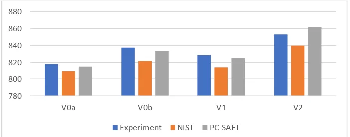
[image:4.595.131.482.485.623.2]Figure 2 displays a comparison between the experimental density results obtained at 293.15K and 0.1MPa with the densities computed employing the method developed at NIST [24] and the PC-SAFT EoS. The compo-sition of the Diesel surrogates used was proposed by [25]. They are divided into two accuracy types depending on how close is their composition to real Diesel. V0a and V0b are low accuracy surrogates and V1 and V2 are high-accuracy surrogates. Their composition is summarised in Table 1. The results obtained using the PC-SAFT EoS shows the highest degree of agreement in comparison with the results obtained by [25] employing the NIST method.
Figure 2. Comparison between experimentally measured surrogate densities at 293.15 K and 0.1MPa with the NIST and PC-SAFT predictions. These preliminary results will be extended in a future
publication.
Shock Tube Problem 1
Figure 3 displays the density, temperature, pressure, and velocity results of a transcritical shock tube problem which employs dodecane as working fluid. The domain is x ϵ [0, 1] m. 1600 equally spaced cells were used. Wave transmissive boundary conditions are implemented in the left and right sides. The initial conditions in the left state are ρL=710.0 kg/m3, pL= 30MPa, uL=0m/s; and in the right state are ρR=100kg/m3, pR=10MPa, uR=0m/s. The
simulated time is 2.5 10-4s. The Euler equations are solved in this validation so a direct comparison with the exact 780
800 820 840 860 880
V0a V0b V1 V2
ICLASS 2018, 14 Triennial International Conference on Liquid Atomization and Spray Systems, Chicago, IL, USA, July 22-26, 2018
solver can be performed in order to validate the hyperbolic part of the developed numerical framework. The exact solution has been computed using the methodology described in [26].
The spatial reconstruction step has been performed in two different ways. In the first one, the PC-SAFT EoS is used to compute the sonic fluid velocity and the pressure employing the left and right reconstructed values. In the second one, the pressure and sonic fluid velocity are calculated in the cell centers and then interpolated onto the cell faces.
The large variation in the thermodynamic properties between the left and right states provoke the formation of large spurious pressure. By employing the modified reconstruction and increasing the refinement the oscilla-tions can be reduced to acceptable values, see Figure 3.
Shock Tube Problem 2
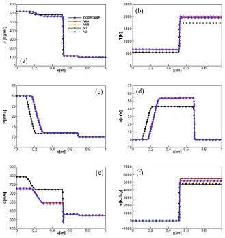
Figure 4 displays the density, temperature, pressure, velocity, sonic fluid velocity and internal energy results of a transcritical shock tube problem which employs dodecane and the V0A, V0B, V1 and V2 Diesel surrogates as working fluids. The composition of the Diesel surrogates is summarized in Table 1. The domain is x ϵ [0, 1] m. 800 equally spaced cells were used. Wave transmissive boundary conditions are implemented in the left and right sides. The initial conditions in the left state are ρL=620kg/m3, pL= 50MPa, uL=0m/s; and in the right state are ρR=100kg/m3, pR=6MPa, uR=0m/s.
[image:5.595.141.477.336.506.2]There is a significant difference between the dodecane and the Diesel surrogates in the results obtained. The temperatures computed using Diesel surrogates are higher than employing dodecane in all the domain. The dif-ferent sonic fluid velocities in the high-density region makes that the expansion wave moves at difdif-ferent velocities.
Table 1. Molar composition for the four Diesel fuel surrogates (V0a, V0b, V1, V2) [25]
Compound V0a V0b V1 V2
n-hexadecane 27.8 - 2.70 -
n-octadecane - 23.5 20.2 10.8
n-eicosane - - - 0.80
heptamethylnonane 36.3 27.0 29.2 -
2-methylheptadecane - - - 7.3
n-butylcyclohexane - - 5.10 19.1 triisopropylcyclohexane - - - 11.0
trans-decalin 14.8 - 5.50 -
perhydrophenanthrene - - - 6.00 1,2,4-trimethylbenzene - 12.5 7.5 - 1,3,5-triisopropylbenzene - - - 14.7
tetralin - 20.9 15.4 16.4
[image:5.595.128.472.537.717.2]1-methylnaphthalene 21.1 16.1 14.4 13.9
Table 2. PC-SAFT pure component parameters [27]
Compound
m
Å
/ k K
n-hexadecane 6.669 3.944 253.59
n-octadecane 7.438 3.948 254.90
n-eicosane 8.207 3.952 255.96
heptamethylnonane 5.603 4.164 266.46 2-methylheptadecane 7.374 3.959 254.83 n-butylcyclohexane 3.682 4.036 282.41 1,3,5-triisopropylcyclohexane 4.959 4.177 297.48
trans-decalin 3.291 4.067 307.98
perhydrophenanthrene 4.211 3.851 337.52 1,2,4-trimethylbenzene 3.610 3.749 284.25 1,3,5-triisopropylbenzene 5.178 5.178 296.68
tetralin 3.088 3.996 337.46
ICLASS 2018, 14 Triennial International Conference on Liquid Atomization and Spray Systems, Chicago, IL, USA, July 22-26, 2018
[image:6.595.136.462.86.308.2]Figure 3. Shock Tube Problem 1. Comparisons of (a) density, (b) temperature, (c) velocity and (d) pressure profiles: exact solution and numerical solutions. Numerical solution 1: Pressure and sonic fluid velocity computed at the faces using the EoS. Numerical solution 2: Pressure and sonic fluid velocity interpolated at the faces.
Figure 4. Shock Tube Problem 2. Comparison of the (a) density, (b) temperature, (c) pressure, (d) x-velocity, (e) sonic fluid velocity, (f) internal using as working fluids dodecane and the Diesel surrogates (Table 1)
(a)
(b)
(c) (d)
(e) (f) (a)
(b)
[image:6.595.132.461.367.714.2]ICLASS 2018, 14 Triennial International Conference on Liquid Atomization and Spray Systems, Chicago, IL, USA, July 22-26, 2018 Two-dimensional cases
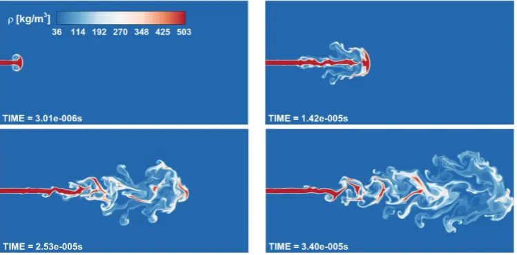
The results of a planar two-dimensional injection of Diesel is presented in this section. The fuel employed is the surrogate V0a. A structured mesh is applied with a uniform cell distribution. The cell size is 7.1µm × 7.1µm. The domain used is 5mm × 2.5mm. The parabolic sub-step is included into these simulations, without sub-grid scale modelling for turbulence or heat/species diffusion. The CFL number is set at 0.8. Transmissive boundary conditions are applied at the top, bottom and right boundaries while a wall condition is employed at the left boundary. A flat velocity profile is imposed at the inlet. The velocity of the jet is 200 m/s and the diameter of the exit nozzle is 0.1mm.
High-load Diesel engine conditions are considered in the combustion chamber, similar to the ones described by [28]. The case is initialized using a pressure in the chamber of 1.11MPa. The temperature of the nitrogen is 973k. The pressures at which vapor-liquid equilibrium exists in a Diesel-nitrogen mixture are much higher than the pressures found in Diesel engine combustion chambers. Then, to be sure that the fuel vaporization step is avoided, the temperature at which the fuel is injected has to be higher than the maximum temperatures encountered in the Diesel-nitrogen phase boundaries, see Figure 5. Thus, the fuel is injected at a temperature of 727K. This is a transcritical case because the surrogate V0a critical temperature is higher than this value (735K).
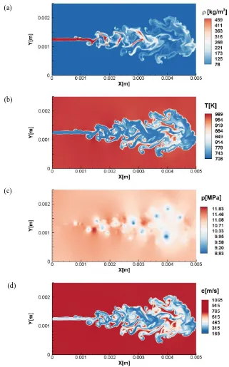
[image:7.595.179.412.363.508.2]Figure 5 shows how the jet does not cross the two-phase region which means that phase separation does not occur. When the jet enters the elevated temperature environment of the chamber, the velocity gradients at the jet surface generate a vortex rollup that finally breakup into ligament-shaped structures, see Figure 6. The Kelvin Helmholtz instability can be observed in the shear layer, which is similar to a gas/gas turbulent mixing case. The jet is quickly heated to a gas-like supercritical state after the injection takes place. It must be highlighted that the mesh resolution is not enough to resolve all the scales (the aim of these simulations is to test the developed nu-merical framework). Moreover, the 2D simulation cannot resolve turbulence. Figure 7 shows the density, pressure, sonic fluid velocity and temperature results at 3.4*10-5s.
Figure 5. Scattered data of composition and temperature of the Diesel injection and phase boundaries from VLE at different pressures.
[image:7.595.115.490.559.744.2]ICLASS 2018, 14 Triennial International Conference on Liquid Atomization and Spray Systems, Chicago, IL, USA, July 22-26, 2018
Figure 7. Results of the simulation of the planar V0a Diesel surrogate jet at 3.4*10-5 s.
(a) density, (b) temperature, (c) pressure, (d) sonic fluid velocity.
Summary and Conclusions
A numerical framework was developed to simulate Diesel jets applying the PC-SAFT EoS. Four different Diesel surrogates are employed. They are divided into two accuracy types depending on how close their compo-sition is to real Diesel. Practical simulations can be carried out reducing the number of times the PC-SAFT EoS is employed by computing the pressure and sonic fluid velocity in the cell centres and performing a reconstruction of these variables at the faces. This technique is found to smooth-out the spurious pressure oscillations associated with conservative schemes used along real-fluid EoS. A two-dimensional simulation of a four component Diesel surrogate planar jet has been performed to demonstrate the capability of the code to predict Diesel-air mixing.
Acknowledgements
This project has received funding from the European Union Horizon-2020 Research and Innovation Pro-gramme with grant Agreement No 675528.
(a)
(b)
ICLASS 2018, 14 Triennial International Conference on Liquid Atomization and Spray Systems, Chicago, IL, USA, July 22-26, 2018
References
[1] L. L. Tavlarides and G. Antiescu, “SUPERCRITICAL DIESEL FUEL COMPOSITION, COMBUSTION PROCESS AND FUEL SYSTEM,” 2009.
[2] G. Anitescu, Supercritical fluid technology applied to the production and combustion of diesel and biodiesel fuels. Syracuse University, 2008.
[3] R. Lin, Issues on clean diesel combustion technology using supercritical fluids: thermophysical properties and thermal stability of diesel fuel. Syracuse University, 2011.
[4] M. S. Wertheim, “Fluids with highly directional attractive forces.I. Statistical thermodynamics,” J. Stat. Phys., vol. 35, no. 1–2, pp. 19–34, 1984.
[5] M. S. Wertheim, “Fluids with highly directional attractive forces. II. Thermodynamic perturbation theory and integral equations,” J. Stat. Phys., vol. 35, no. 1–2, pp. 35–47, 1984.
[6] M. S. Wertheim, “Fluids with highly directional attractive forces. III. Multiple attraction sites,” J. Stat. Phys., vol. 42, no. 3–4, pp. 459–476, 1986.
[7] M. S. Wertheim, “Fluids with Highly Directional Attractive Forces . IV . Equilibrium Polymerization,” vol. 42, pp. 477–492, 1986.
[8] W. G. Chapman, K. E. Gubbins, G. Jackson, and M. Radosz, “SAFT: Equation-of-state solution model for associating fluids,” Fluid Phase Equilib., vol. 52, no. C, pp. 31–38, 1989.
[9] W. G. Chapman, G. Jackson, and K. E. Gubbins, “Phase equilibria of associating fluids,” Mol. Phys., vol. 65, no. 5, pp. 1057–1079, Dec. 1988.
[10] N. Khare Prasad, “Predictive Modeling of Metal-Catalyzed Polyolefin Processes,” 2003.
[11] H. Terashima and M. Koshi, “Approach for simulating gas-liquid-like flows under supercritical pressures using a high-order central differencing scheme,” J. Comput. Phys., vol. 231, no. 20, pp. 6907–6923, 2012. [12] T. Schmitt, L. Selle, A. Ruiz, and B. Cuenot, “Large-Eddy Simulation of Supercritical-Pressure Round
Jets,” AIAA J., vol. 48, no. 9, pp. 2133–2144, 2010.
[13] R. Abgrall and S. Karni, “Computations of compressible multifluids,” J. Comput. Phys., vol. 169, pp. 594–623, 2001.
[14] G. Billet and R. Abgrall, “An adaptive shock-capturing algorithm for solving unsteady reactive flows,”
Comput. Fluids, vol. 32, no. 10, pp. 1473–1495, 2003.
[15] P. C. Ma, L. Bravo, and M. Ihme, “Supercritical and transcritical real-fluid mixing in diesel engine applications,” 2014, pp. 99–108.
[16] P. C. Ma, Y. Lv, and M. Ihme, “An entropy-stable hybrid scheme for simulations of transcritical real-fluid flows,” J. Comput. Phys., vol. 340, no. March, pp. 330–357, 2017.
[17] P. C. Ma, Y. Lv, and M. Ihme, “Numerical methods to prevent pressure oscillations in transcritical flows,” no. 1999, pp. 1–12, 2017.
[18] J. Matheis and S. Hickel, “Multi-component vapor-liquid equilibrium model for LES of high-pressure fuel injection and application to ECN Spray A,” Int. J. Multiph. Flow, vol. 99, pp. 294–311, 2017. [19] R. W. Houim and K. K. Kuo, “A low-dissipation and time-accurate method for compressible
multi-component flow with variable specific heat ratios,” J. Comput. Phys., vol. 230, no. 23, pp. 8527–8553, 2011.
[20] C. Rodriguez, A. Vidal, P. Koukouvinis, and M. Gavaises, “Supercritical and transcritical real-fluid mixing using the PC-SAFT EOS.”
[21] R. J. Spiteri and S. J. Ruuth, “A New Class of Optimal High-Order Strong-Stability-Preserving Time Discretization Methods,” SIAM J. Numer. Anal., vol. 40, no. 2, pp. 469–491, 2002.
[22] T. H. Chung, M. Ajlan, L. L. Lee, and K. E. Starling, “Generalized multiparameter correlation for nonpolar and polar fluid transport properties,” Ind. Eng. Chem. Res., vol. 27, no. 4, pp. 671–679, Apr. 1988.
[23] M. R. Riazi and C. H. Whitson, “Estimating diffusion coefficients of dense fluids,” Ind. Eng. Chem. Res., vol. 32, no. 12, pp. 3081–3088, 1993.
[24] E. W. Lemmon, M. L. Huber, and M. O. McLinden, “NIST reference fluid thermodynamic and transport properties–REFPROP.” version, 2002.
[25] C. J. Mueller et al., “Diesel Surrogate Fuels for Engine Testing and Chemical-Kinetic Modeling:
Compositions and Properties,” Energy and Fuels, vol. 30, no. 2, pp. 1445–1461, 2016.
[26] N. Kyriazis, P. Koukouvinis, and M. Gavaises, “Numerical investigation of bubble dynamics using tabulated data,” Int. J. Multiph. Flow, vol. 93, no. Supplement C, pp. 158–177, 2017.
[27] J. Gross and G. Sadowski, “Perturbed-Chain SAFT: An Equation of State Based on a Perturbation Theory for Chain Molecules,” Ind. Eng. Chem. Res., vol. 40, no. 4, pp. 1244–1260, 2001.
[28] G. Lacaze, A. Misdariis, A. Ruiz, and J. C. Oefelein, “Analysis of high-pressure Diesel fuel injection processes using LES with real-fluid thermodynamics and transport,” Proc. Combust. Inst., vol. 35, no. 2, pp. 1603–1611, 2015.
![Figure 1. Schematic representation of the attractive and repulsive contributions of the SAFT EoS and the PC-SAFT EoS [10]](https://thumb-us.123doks.com/thumbv2/123dok_us/1388791.92024/2.595.128.496.633.735/figure-schematic-representation-attractive-repulsive-contributions-saft-saft.webp)
![Table 1. Molar composition for the four Diesel fuel surrogates (V0a, V0b, V1, V2) [25]Compound V0a V0b V1 V2](https://thumb-us.123doks.com/thumbv2/123dok_us/1388791.92024/5.595.141.477.336.506/table-molar-composition-diesel-fuel-surrogates-compound-v.webp)