City, University of London Institutional Repository
Citation
:
Liu, Q., He, X., Qiao, X., Sun, T. ORCID: 0000-0003-3861-8933 and Grattan, K.
T. V. ORCID: 0000-0003-2250-3832 (2019). Design and Modeling of a High Sensitivity Fiber
Bragg Grating-Based Accelerometer. IEEE Sensors Journal, 19(14), pp. 5439-5445. doi:
10.1109/JSEN.2019.2904218
This is the accepted version of the paper.
This version of the publication may differ from the final published
version.
Permanent repository link:
http://openaccess.city.ac.uk/id/eprint/22991/
Link to published version
:
http://dx.doi.org/10.1109/JSEN.2019.2904218
Copyright and reuse:
City Research Online aims to make research
outputs of City, University of London available to a wider audience.
Copyright and Moral Rights remain with the author(s) and/or copyright
holders. URLs from City Research Online may be freely distributed and
linked to.
City Research Online:
http://openaccess.city.ac.uk/
[email protected]
Design and Modeling of a High Sensitivity Fiber
Bragg Grating-Based Accelerometer
Qinpeng
Liu,
Xue
He,
Xueguang
Qiao,
Tong
Sun,
and
Kenneth
T.
V.
Grattan
Abstract— Use of a detailed theoretical model has allowed the
optimization of the design of a high sensitivity accelerometer, based on a fiber Bragg grating (FBG) and an accelerometer based on this design has been demonstrated experimentally. With a universal model based on double-point encapsulation established, the performance of the device in terms of its optimal sensitivity and frequency distribution has been analyzed, with an optimization ‘figure of merit’ using the product of the sensitivity and the resonant frequency being presented. The experimental results obtained indicate that the FBG-based accelerometer thus developed shows a broad, flat frequency band, a corresponding flat range sensitivity of ∼152.0pm/G, a resonant frequency of 441.0Hz, and a cross-axis sensitivity of less than 3.6% of the main-axis sensitivity. An accelerometer of this type and with this performance thus has the potential for the important field of low frequency oil-gas seismic exploration.
Index Terms— Fiber Bragg grating (FBG), accelerometer,
sen-sitivity, theoretical model.
I. INTRODUCTION
F
IBER Bragg Grating (FBG)-based sensing is an impor-tant branch of optical fiber technology and exploits the many advantages of the technology including immunity to electromagnetic interference, high temperature survivability, corrosion resistance, small size and ability to be multiplexed. Sensors of this type can be used to measure many dif-ferent physical parameters, such as pressure, displacement, angle, and acceleration, suiting them well for important applications in the structural monitoring, geodynamics and seismic exploration fields [1]–[7]. Compared with conven-tional electronic sensors, the fiber optic approach has unique advantages that suit it well to hazardous measurement sit-uations, such as petroleum exploration where such devicesThis work was supported in part by the National Science Foundation under Grant 61735014, and in part by the Shaanxi Provincial Education Department under Program 18JS093.
Q. Liu, X. He, and X. Qiao are with the Key Laboratory on Photoelectric Oil-gas Logging and Detecting, Ministry of Education, School of Science, Xi’an Shiyou University, Xi’an 710072, China (e-mail: [email protected]; [email protected]; [email protected]).
T. Sun is with the School of Mathematics, Computer Science and Engineering, City, University of London, London EC1V 0HB, U.K. (e-mail:[email protected]).
K. T. V. Grattan is with the City Graduate School and the School of Mathematics, Computer Science and Engineering, City, University of London, London EC1V 0HB, U.K. (e-mail: [email protected]).
accelerometers based on the use of an elastic diaphragm have the useful characteristic of higher sensitivity to the normal dis-placement but relatively insensitivity to lateral disdis-placement. This benefit then helps to reduce cross-sensitivity to lateral displacement effects, which is important in practical use. Muller et al. [23] have proposed a theoretical approach to mod-eling an accelerometer using double diaphragms. Li et al. [24] also presented a FBG accelerometer design based on the double diaphragms, quoting a sensitivity of 24.3pm/G and resonant frequency of 900Hz. Additionally, Luo et al. [25] have developed a further FBG accelerometer approach in which the resonant frequency is 143Hz and the sensitiv-ity 211pm/G. Liu et al. [26] have also reported an innova-tive FBG scheme using a single diaphragm, with sensitivity of 36.6 pm/G and resonance frequency of 255 Hz. Important here is that the cross-axis sensitivity is less than 1.3 % of the main-axis sensitivity. Liu et al. [27] has developed a device showing a large frequency range and high sensitivity, where the reported sensitivity is 23.8pm/G, the resonant frequency is 1240Hz, and the cross-sensitivity is less than 2.1%.
Balancing the key performance characteristics of sensi-tivity and resonant frequency is difficult but important to create suitable criteria for achieving optimum performance and allowing cross-comparison with different, competing devices to meet particular operational systems requirements. In this work, the theoretical underpinning of an enhanced FBG-based accelerometer is discussed, thus establishing and an approach to optimization of the performance of FBG-based accelerome-ter devices. Here the product of the sensitivity and the resonant frequency (PSRF) is introduced as a ‘figure of merit’ to allow easier comparison and thus optimization of the overall performance, allowing an optimum design for the important frequency range of 1–160Hz to be proposed. Referencing previous work, it can thus be seen when this PSRF ‘figure of merit’ reaches its optimum value and the sensitivity reaches its maximum within a given frequency band, allowing the design of a sensor to be more compact and thus simpler in operation. This analysis approach is thus well suited to the identification of device designs which show good performance in the low frequency range, making them well-tailored to oil and gas seismic exploration.
II. MODELING ANDDESIGNOPTIMIZATION A. The Theoretical Model Used
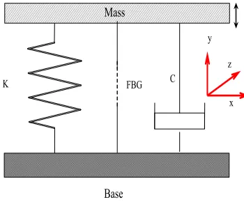
The theoretical model used in this work of an FBG-based accelerometer using double-point encapsulation is shown in Fig. 1. In essence, the model can be simplified into a single degree of freedom, mass-spring system, where K is the stiffness of the system, and C is the damping constant. According to coupled-mode theory, the center wavelength shift
λB of the FBG can be expressed as follows [30]:
λB
λB =(
1−Pe)ε (1)
where Pe is the effective elasto-optical coefficient and ε
[image:3.612.346.521.58.203.2]is the axial strain on the FBG. According to the princi-ples of elastic and structural mechanics, the Eq.1 can be
Fig. 1. Simple theoretical model of FBG accelerometer: K is stiffness of system, C is the damping constant and the Fiber Bragg Grating is represented by FBG.
expressed as [19], [27]
λB
λB =
(1−pe)M a
Lf(Kf +Ks)
(1−γ2)2+(2ξγ )2
(2)
where Lf is the length of the fiber used, Kf=Efd2/4Lf is its stiffness, Ks is the stiffness of the accelerometer structure,
γ = f/fn is the ratio of the frequency to the resonant
frequency, ξ is the damping ratio and M is the mass of the inertial system. From the definition of the acceleration sensitivity and the resonant frequency, the sensitivity Sf and
the resonant frequency fn can be expressed as
fn =
1 2π
Ks+Kf
M (3)
Sf = (1− pe)MλB
Lf(Kf+Ks)
(1−γ2)2+(2ξγ )2
(4)
Asγ tends to zero, the expression for the sensitivity can be simplified as the static sensitivity, SI, is independent of the applied frequency, and thus SI can be rewritten as
SI = (
1−pe)mλB Lf(Kf +Ks)
(5)
In general, the sensitivity is a function of the frequency and in the design of an effective FBG-based accelerometer, the static sensitivity SI, is of greatest importance because it is very close to the ‘flat range’ sensitivity. High sensitivity and low fluctuation over a flat frequency range is a key design goal, not only to improve the resolution of signal, but also to improve the response characteristics in the low frequency band. The relationship between the theoretical sensitivity and the resonant frequency has important significance for creating an optimum device design. The sensitivity SI and the resonant frequency fn normalized with respect to the ratio R(Ks/Kf) as a function of Lf is shown in Fig. 2 for different masses.
It can be seen that the stiffness ratio R has a major influence on the sensitivity in the low frequency band, and as the frequency increases, the ratio R has a smaller influence on the sensitivity. As Kf =Efd2/4Lf, the sensitivity is a function of
Fig. 2. Theoretical relationship between the sensitivity and resonant frequency with different stiffness ratios, R, and mass (Ef =7.2×10¹⁰ Pa,
[image:4.612.330.542.58.217.2]d=0.125 mm).
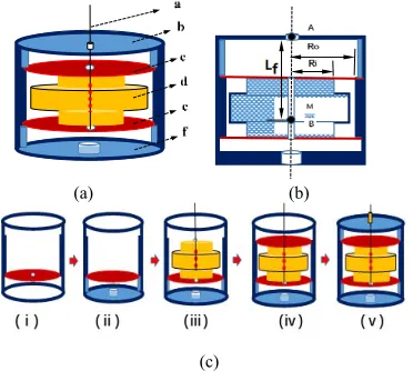
Fig. 3. Schematic of the FBG accelerometer designs. (a) Structural diagram where a is fiber, b is head cover, c is up diaphram, d is interial mass, e is low diaphram, f is base. (b) Cross-sectional view where Ro is outside radius, Ri is inside radius, Lf is the distance between poin A. (c) Schematic of the fabrication procedure for the device (i) to (v).
accelerometers with different lengths, Lf, of the fiber used
and the same stiffness ratio, R, may have a similar sensitivity and resonant frequency, which then can be optimized. The maximum sensitivity that can be achieved is 1000pm/G – but the resonant frequency drops sharply below 50Hz. For the low frequency band (<100Hz), the length of fiber, has a significant influence on the resonant frequency (which cannot be ignored over this range, but it can more readily be ignored in the higher frequency range (>500Hz)).
B. Design and Optimization
The structure and fabrication issues for the optimization of the sensor system are shown schematically in Fig. 3. The inertial cylinder mass used is clamped between the two diaphragms, and is characterized by a thick middle and a thin end, with a through-hole is located at the central axis. A FBG is fixed between point A of the head cover and point B of the mass, as shown, this allowing the overall size of the device potentially to be reduced and thus the sensor to be more compact. When the sensor is subjected to acceleration along
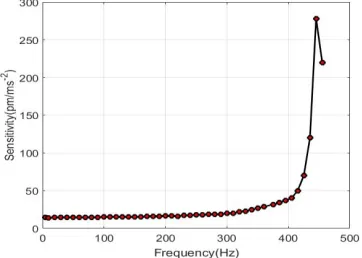
Fig. 4. The relation between sensitivity and frequency, Ed=1.35×10¹¹Pa,
Lf =10 mm, Ef =7.2×10¹⁰Pa, d=0.125 mm.
main axis, the inertial force induces a normal displacement of the diaphragms, resulting in a wavelength shift of the FBG. From the familiar principles of structural mechanics, the stiff-ness of the structure can be expressed as [24], [26]:
Ks =
8πEdH3
3β(1−μ)Ro2
(6)
β=1−(Ri
Ro) 2
−4(Ri
Ro) 2
(ln Ri Ro)
2
/(1− Ri
2 Ro2
) (7)
where Ed, H, Ri,Ro,μ are the Young modulus, the
thick-ness, the inside radius, the external radius and Possion’s ratio respectively for the diaphragm. Combined with the Eq.3, Eq.5 and Eq.6, the sensitivity SI and resonant frequency SI can be expressed as is shown in Eq.8 and Eq.9 respectively.
SI =
3λB(1−Pe) Lf[ 8πEdH
3
3β(1−μ)Ro2 +
Efd2 4Lf ]
M (8)
fn =
8πEdH3
3Mβ(1−μ)Ro2
+ Efd2
4M Lf
(9)
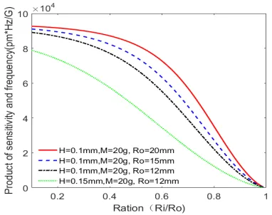
[image:4.612.78.264.265.432.2]Fig. 5. The Product of sensitivity and resonant frequency. TABLE I
PARAMETERSUSED IN THEACCELEROMETERMODELING
can be expressed by Eq.8 and Eq.9, normalized with respect to the radius Ro and the thickness H as a function of the
ratio Ri/Roand this is plotted in Fig. 5. It can be seen that the
PSRF decreases with increasing ratio ( Ri/Ro), as generally
when the ratio increases, the rate of sensitivity decrease is greater than the rate of frequency increase, and the smaller the ratio ( Ri/Ro),the lower is the resonance frequency. As the
ratio ( Ri/Ro) rises from 0.1 to 0.5, the PSRF drops slowly,
following which it decreases sharply when the ratio is >0.5. That is to say for best performance, the ratio ( Ri/Ro) should
not be too large and an optimum value exists. Thus for the low-frequencies experienced in oil/gas seismic exploration (where the range is typically up to 160Hz), to make sure the ‘flat operational range’ to being three times the working frequency. Combined with the relationship between the sensitivity and the resonant frequency, the core parameter Ri/Ro is then given
by the value 0.5 and the other key parameters are as given in Table 1, where the theoretical sensitivity is 150.0pm/G, and the theoretical resonant frequency is ∼454.0Hz, yielding a corresponding PSRF figure of merit of 6.8×10⁴pmHz/G.
III. EXPERIMENT ANDDISCUSSION
The experimental setup used in this work is shown in Fig. 6, where the FBG accelerometer is fixed to a vibration table and a commercial piezoelectric accelerometer is used for cross-calibration. The FBG Interrogator (Type sm130 from Micron Optics, USA) with a wavelength reproducibility of 1 pm,
Fig. 6. Experimental setup of the system.
a scan frequency of 1 kHz and a wavelength range of 80 nm is used. In the experiment, the ambient temperature is recorded as 26 ◦C - but the effect of the temperature on the wave-length recorded is small (equivalent to <1Hz), over the time of the measurement was taken, any temperature effect can be ignored. In addition to this, the main factors that affect the temperature range are prestress (corresponding to ∼1.15 nm), encapsulating adhesive (353ND), shell (alu-minum alloy) diaphragm (QBe2), all of which are considered comprehensively. The theoretical temperature range consid-ered is from −20 ◦C to 60 ◦C, but it is extremely difficult to change the temperature while measuring the acceleration in the experiment in the set up used. As a result, the extent of the temperature measurement range has not been experi-mentally determined in this work, but could represent a future investigation.
A. Linear Responsivity
Linear responsivity is an important characteristic of an accelerometer, defined as the relationship between the output wavelength and the applied acceleration. In the experiment carried out, the applied acceleration is sinusoidal in form, where the peak amplitude of the sinusoidal is given in units of G (where 1 G =10.0 m/s2)and the corresponding output
signal is the wavelength of the FBG (it is also a harmonic oscillation, where the amplitude of the harmonic oscillation is the response to the applied acceleration). Experimental results obtained show that the accelerometer presents an extremely linear response, seen in Fig. 7, for a 100Hz and 160Hz har-monic oscillation output of the FBG accelerometer, and yield-ing a consequent sensitivity of 152.2pm/G for 160Hz. Fig. 8 shows the wavelength response in the time domain (where the harmonic oscillation output for the different accelerations at 100Hz and 160Hz are shown).
B. Amplitude-Frequency Characteristic
[image:5.612.58.287.268.408.2]Fig. 7. Linear response of the accelerometer at 100Hz and 160 Hz.
Fig. 8. Response in the time domain at 100Hz and 160 Hz.
Fig. 9. Amplitude-frequency curve of the FBG accelerometer.
that resonant frequency. In order to investigate further the amplitude-frequency characteristic of the FBG accelerometer design, the amplitude of the input signal is fixed at 0.1G, while the frequency of the applied signal is varied from 5 to 455 Hz. The amplitude-frequency response of the accelerometer that results is shown in Fig. 9, illustrating that the sensor has a broad flat response. In particular, what is important is that the low frequency range extends below 5Hz and with the approximate resonant frequency at 445 Hz, this offers a valuable characteristic for the device. The FBG Interrogator used (Type sm130) has a scan frequency of 1 kHz, setting a limit on the higher frequency signals that can be obtained. In order to obtain more accurate resonant frequency data, the Fast Fourier Transform (FFT) method has been adopted,
Fig. 10. Shock response in the time domain.
Fig. 11. FFT of the shock response (Figure 10).
by using a manual impulse signal. The Fig. 10 shows the impulse signal in the time domain, while Fig. 11 shows the results of applying the fast Fourier transform (FFT) that results. The figure of 441Hz, obtained by this method is more reliable than that obtained previously (445Hz). Measure-ment results thus obtained agree well (within experiMeasure-mental error) with the theoretical resonant frequency calculated to be∼454Hz. In addition to this, the sensor presents a damped oscillation response. In practice, a damping fluid element has not been included to minimize the complexity of the sensor, with damping mainly due to the nature of the structure and the encapsulation.
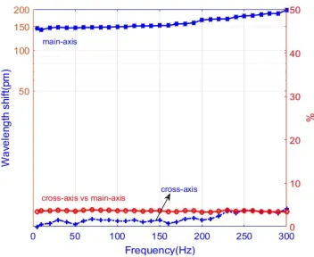
C. Cross-Sensitivity
[image:6.612.73.277.242.381.2] [image:6.612.85.266.415.544.2]Fig. 12. The cross-sensitivity and main-sensitivity where the acceleration is 1G.
Fig. 13. Noise level in different frequency bands. TABLE II
QUANTITATIVE COMPARISON OF PERFORMANCE OF THE REPORTED SCHEMES
D. Noise Level
The noise level is an important parameter for all kinds of accelerometer systems, as it reflects the ability of the device to detect weak signals over different frequency bands in practical applications. For this FBG accelerometer system, the equiva-lent noise over different bands was first measured and com-bined with the resolution ratio, allowing the noise level shown in Fig. 13 to be obtained. This is given by 0.26mG/Hz0.5over the 160Hz frequency band.
IV. CONCLUSION
A theoretical model has been developed, showing the high sensitivity of a FBG accelerometer designed. Based on the results of a model analyzed, a high-performance FBG accelerometer was developed, optimized and its performance discussed. The concept of a ‘figure of merit’, the product of sensitivity and frequency (PSRF) is introduced to allow a sim-ple means of evaluation of the overall performance. Through
appropriate theoretical modeling to allow the optimization of the design, the work undertaken has shown the following key features. Firstly, an effective theoretical model illustrating the high sensitivity of the FBG-based accelerometer design has been established and the theoretical relationship between the limit of the sensitivity and the resonant frequency has been proposed, this being dependent on the stiffness ratio. This is significant in improving performance and facilitating the miniaturization of the FBG accelerometer design. Secondly, the concept of the ‘figure of merit’, the PSRF, is introduced for comparison of the optimized overall performance, where the larger the PSRF, the closer the sensitivity is to the extreme limit of the theoretical model. Thus, under the conditions of the same frequency band, the larger the PSRF, the better the performance. Thirdly, the FBG accelerometer provides a broad frequency range of operation from 5 to 300 Hz, where the corresponding sensitivity ranges from 145.0 to 198.0 pm/G. An excellent feature is the low cross-axis sensitivity, which is less than 3.6% of the main-axis sensitivity. Thus, such a design is a good candidate for use in ‘low frequency’ oil and gas seismic exploration, and the theoretical analysis used provides an excellent deign framework giving confidence in the FBG-based accelerometer design that has been developed. The performance of the FBG-based device discussed in this work compares well with those considered in the literature, as can be seen from Table II, which summarizes performance data from a number of previously reported devices. The generic model based on double-point encapsulation which has been established shows a sensitivity obtained which is greater than other sensor designs when viewing this within a similar frequency band [17], [19], [21]. The ‘figure of merit’ (PSRF) used is much higher than that for the other sensors, data on which has been taken from the literature [8]–[29]. Data sum-marized in Table II thus show key features of the performance and sensitivity achieved in light of published work.
REFERENCES
[1] P. F. da C. Antunes et al., “Optical fiber accelerometer system for structural dynamic monitoring,” IEEE Sensors J., vol. 9, no. 11, pp. 1347–1354, Nov. 2009.
[2] P. Antunes, R. Travanca, H. Varum, and P. André, “Dynamic monitoring of mobile telecommunication towers exposed to natural loading with a FBG biaxial accelerometer,” in Proc. 16th OECC, Kaohsiung, Taiwan, Jul. 2011, pp. 591–592.
[3] Y. Zhang et al., “Fiber Bragg grating sensors for seismic wave detec-tion,” Proc. SPIE, vol. 5855, pp. 1008–1011, Aug. 2005.
[4] X. Qiao, Z. Shao, W. Bao, and Q. Rong, “Fiber Bragg grating sensors for the oil industry,” Sensors, vol. 17, p. 429, Feb. 2017.
[5] A. Laudati et al., “A fiber optic Bragg grating seismic sensor,” Proc.
SPIE, vol. 6619, pp. 66191C-1–66191C-4, Jul. 2007.
[6] X. L. Zhang et al., “Reliable high sensitivity FBG geophone for low frequency seismic acquisition,” Measurement, vol. 129, pp. 62–67, Dec. 2018.
[7] I. Talebinejad, C. Fischer, and F. Ansar, “Low frequency fiber optic accelerometer for civil structural health monitoring,” Proc. SPIE, Apr. 2009, vol. 7294, Art. no. 729412.
[8] M. D. Todd, G. A. Johnson, B. A. Althouse, and S. T. Vohra, “Flexural beam-based fiber Bragg grating accelerometer,” IEEE Photon. Technol.
Lett., vol. 10, no. 11, pp. 1605–1607, Nov. 1998.
[9] A. Mita and I. Yokoi, “Fiber Bragg grating accelerometer for structural health monitoring,” in Proc. 5th Int. Conf. Motion Vib. Control, 2000, pp. 4–8.
[11] M. M. Khan, N. Panwar, R. Dhawan, “Modified cantilever beam shaped FBG based accelerometer with self temperature compensation,” Sens.
Actuators A, Phys., vol. 205, pp. 79–85, Jan. 2014.
[12] D. Feng et al., “A fiber Bragg grating accelerometer based on a hybridization of cantilever beam,” IEEE Sensors J., vol. 15, no. 3, pp. 1532–1537, Mar. 2015.
[13] N. Basumallick, P. Biswas, K. Dasgupta, and S. Bandyopadhyay, “Design optimization of fiber Bragg grating accelerometer for maximum sensitivity,” Sens. Actuators A, Phys., vol. 194, pp. 31–39, May 2013. [14] X. Zhang, Q. Rong, H. Sun, S. Yang, L. Yuan, and M. Hu,
“Low-frequency fiber Bragg grating accelerometer based on a double-semicircle cantilever,” Opt. Fiber Technol., vol. 20, pp. 190–193, Jun. 2014.
[15] J. Zhang et al., “Flextensional fiber Bragg grating-based accelerometer for low frequency vibration measurement,” Chin. Opt. Lett., vol. 9, no. 9, Sep. 2011, Art. no. 090607.
[16] Q. Liu, Z. Jia, H. Fu, D. Yu, H. Gao, and X. Qiao, “Double cantilever beams accelerometer using short fiber Bragg grating for eliminating chirp,” IEEE Sensors J., vol. 16, pp. 6611–6615, Sep. 2016.
[17] Y. Yu, Z. Meng, and H. Luo, “Study on fiber Bragg grating vibrating sensors with symmetry push-pull configuration,” Semicond.
Optoelec-tron., vol. 32, no. 1, pp. 118–122, 2011.
[18] Q.-P. Liu, X.-G. Qiao, J.-L. Zhao, Z.-A. Jia, H.-W. Fu, and H. Gao, “Study on fiber Bragg grating acceleration sensing based on elastic tube,”
J. Optoelectron. Laser, vol. 23, no. 7, pp. 1227–1232, Mar. 2012.
[19] J. Wang, Y. Zeng, C. Lin, Z. Hu, G. Peng, and Y. Hu, “A miniaturized FBG accelerometer based on a thin polyurethane shell,” IEEE Sensors
J., vol. 16, no. 15, pp. 1210–1216, Mar. 2016.
[20] Y. S. Zhang et al., “Study on a fiber Bragg grating accelerometer based on compliant cylinder,” Opt. Fiber Technol., vol. 26, pp. 229–233, Dec. 2015.
[21] N. Gutiérrez, P. Galvín, and F. Lasagni, “Low weight additive man-ufacturing FBG accelerometer: Design, characterization and testing,”
Measurement, vol. 117, pp. 295–303, Mar. 2018.
[22] X. Wang, Y. Guo, L. Xiong, and H. Wu, “High-frequency optical fiber Bragg grating accelerometer,” IEEE Sensors J., vol. 18, no. 12, pp. 4954–4960, Jun. 2018.
[23] M. S. Müller, T. C. Buck, and A. W. Koch, “Fiber Bragg grating-based acceleration sensor,” in Proc. Int. Symp. Optomechatronic Technol., Istanbul, Turkey, 2009, pp. 127–132.
[24] X.-C. Li, S. Liu, W.-T. Zhang, F.-X. Zhang, F. Li, and Y.-L. Liu, “Study on low-frequency characteristic of double-diaphragm fiber Bragg grating geophone,” J. Optoelectron. Laser, vol. 21, no. 4, pp. 529–532, Apr. 2010.
[25] X. D. Luo, X. G. Qiao, Z. A. Jia, M. Shao, and D. Q. Feng, “The experimentation of fiber Bragg grating geophone,” Prog. Geophys., vol. 27, no. 3, pp. 1203–1206, Mar. 2012.
[26] Q. P. Liu, X. G. Qiao, J. L. Zhao, Z. A. Jia, H. Gao, and M. Shao, “Novel fiber Bragg grating accelerometer based on diaphragm,” IEEE
Sensors J., vol. 12, no. 10, pp. 3000–3004, Oct. 2012.
[27] Q. Liu, X. Qiao, Z. Jia, H. Fu, H. Gao, and D. Yu, “Large frequency range and high sensitivity fiber Bragg grating accelerometer based on double diaphragms,” IEEE Sensors J., vol. 14, no. 5, pp. 1499–1504, May 2014.
[28] L. Qiu, L. Liang, D. Li, and G. Xu, “Theoretical and experimental study on FBG accelerometer based on multi-flexible hinge mechanism,” Opt.
Fiber Technol., vol. 38, pp. 142–146, Nov. 2017.
[29] F. Liu, Y. Dai, J. M. Karanja, and M. Yang, “A low frequency FBG accelerometer with symmetrical bended spring plates,” Sensors, vol. 17, no. 1, p. 206, Jan. 2017.
[30] K. O. Hill and G. Meltz, “Fiber Bragg grating technology fundamentals and overview,” J. Lightw. Technol., vol. 15, no. 8, pp. 1263–1276, Aug. 1997.
Qinpeng Liu was born in Anhui, China, in 1977. He received the Ph.D.
degree from the School of Northwestern Polytechnical University in 2015, major in optical engineering. His current research interests are mainly focused on optical fiber sensing and their applications.
Xue He was born in Shanxi, China, in 1994. She is currently pursuing the
M.S. degree with the Key Laboratory on Photoelectric Oil-Gas Logging and Detecting, Ministry of Education, Xi’an Shiyou University.
Xueguang Qiao was born in Shanxi, China, in 1955. He received the Ph.D.
degree in science from the Xi’an Institute of Optics and Fine Mechanics, Chinese Academy of Sciences, in 1998, major in optics. His current research interests include optoelectronic technology, optical fiber communication, and sensing.
Tong Sun received the B.E., M.E., and D.Eng. degrees from the Department
of Precision Instrumentation, Harbin Institute of Technology, Harbin, China, in 1990, 1993, and 1998, respectively, and the Ph.D. degree in applied physics from the City, University of London, London, U.K., in 1999.
She was an Assistant Professor with Nanyang Technological University, Singapore, from 2000 to 2001, before she rejoined the City, University of London in 2001, as a Lecturer. Subsequently, she was promoted as a Senior Lecturer in 2003, a Reader in 2006, and a Professor in 2008 at the City, University of London, where she is currently the Director of the Research Centre of Sensors and Instrumentation and is leading a research team focused on developing a range of optical fiber sensors for a variety of industrial applications, including structural condition monitoring, early fire detection, homeland security, process monitoring, food quality, and environmental mon-itoring. She has been working closely with partners across disciplines from academia and industry, both in the U.K. and overseas. She has authored or co-authored some 230 scientific and technical papers. Dr. Sun is a member of the Institute of Physics and a Fellow of the Institution of Engineering and Technology. She is a Chartered Physicist and a Chartered Engineer in U.K.
Kenneth T. V. Grattan received the B.Sc. (Hons.) degree in physics from
Queens University Belfast, Belfast, U.K., in 1974, the Ph.D. degree in laser physics in the use of laser-probe techniques for measurements on potential new dye laser systems, and the D.Sc. degree from the City, University of London, London, U.K., in 1992, for his work in sensor systems.
In 1978, he became a Research Fellow with the Imperial College of Science and Technology, to work on advanced photolytic drivers for novel laser systems. In 1983, he joined the City, University of London, as a new blood Lecturer in Physics, being appointed as a Professor of Measurement and Instrumentation, and the Head of the Department of Electrical, Electronic and Information Engineering in 1991. He was the President of the Institute of Measurement and Control in 2000. He was the Dean of the School of Engineering and Mathematical Sciences and the School of Informatics, City, University of London, from 2008 to 2012. He was appointed as the Dean of the City Graduate School in 2012. He has authored more than 700 publications in major international journals and a similar number at international conferences. His research interests include the use of fiber optic and optical systems in the measurement of a range of physical and chemical parameters for industrial applications. He is the Co-Editor of a five volume topical series on Optical Fiber Sensor Technology.