University of Southern Queensland Faculty of Health, Engineering and Sciences
The development of a Light Weight Composite Conveyor Belt
Idler Roller
A dissertation submitted by Barnard Janse van Rensburg
in fulfilment of the requirements of ENG4111 Research Project Part I
ENG4112 Research Project Part II
towards the degree of
Bachelor of Engineering (Mechanical)
Page | ii
Abstract
High incidence of injuries caused by the manual handling of heavy idler rollers is a major concern for the Australian mining industry. Consequently, major mining industry stakeholders called for the development of light weight idler rollers. As a result this project was designed to develop a light weight idler roller using pultruded continuous glass fibre, vinyl ester composite circular hollow section.
Current literature on the subject highlighted the need for non-ferrous light weight idler rollers but offers no real solution. A rigorous test regime, including physical static and dynamic testing in conjunction with finite element analysis, was used to analyse a designed light weight composite prototype idler roller.
Page | iii University of Southern Queensland
Faculty of Health, Engineering and Sciences
Limitations of Use
The Council of the University of Southern Queensland, its Faculty of Health, Engineering and Sciences, and the staff of the University of Southern Queensland, do not accept any responsibility for the truth, accuracy or completeness of material contained within or associated with this dissertation.
Persons using all or any part of this material do so at their own risk, and not at the risk of the Council of the University of Southern Queensland, its Faculty of Health, Engineering and Sciences or the staff of the University of Southern Queensland.
This dissertation reports an educational exercise and has no purpose or validity beyond this exercise. The sole purpose of the course pair entitled “Research Project" is to contribute to the overall education within the student's chosen degree program. This document, the associated hardware, software, drawings, and other material set out in the associated appendices should not be used for any other purpose: if they are so used, it is entirely at the risk of the user.
Page | iv
Certification of Dissertation
I certify that the ideas, designs and experimental work, results, analyses and conclusions set out in this dissertation are entirely my own effort, except where otherwise indicated and acknowledged.
I further certify that the work is original and has not been previously submitted for assessment in any other course or institution, except where specifically stated.
BARNARD JANSE VAN RENSBURG 0050099660
______________________________ Signature
Page | v
Acknowledgements
I wish to acknowledge the support afforded to me in order to fulfil the requirements of this dissertation. It is with pleasure that I would like to thank the following people who contributed tirelessly to my project:
Mr Chris Snook, Project Supervisor – for his technical expertise and advice needed to successfully complete this project to date,
Mr James Bourke, Industry Supervisor – for his constant help, technical advice and practical support,
Mr Andrew Roche, Research and Development Officer – for his time and effort spent assisting my project in many ways,
Mr Nick Ree, Work Experience Student - for his time and effort spent assisting my project,
Wagners Composite Fibre Technology – for the opportunity to develop a composite roller and allowing the use of their world class facilities,
Dr Henriette Janse van Rensburg and Dr Karen Noble – for support and advice given during this project,
Mr Jyrin William Lovett – for his friendship and encouragement, and Mrs Monique Janse van Rensburg – for her patience and support
during this endeavour.
This thesis was produced using Microsoft Word 2010
Barnard Janse van Rensburg
University of Southern Queensland
Page | vi
Table of Contents
Abstract ...ii
Limitations of Use ... iii
Certification of Dissertation ... iv
Acknowledgements ... v
List of figures ... ix
List of tables ... xii
List of Appendices ... xiii
Nomenclature and acronyms... xiv
1 Introduction ... 1
1.1 Project topic ... 1
1.2 Project background ... 1
1.2.1 Queensland coal mining operations ... 2
1.2.2 Bulk material handling ... 4
1.2.3 Conveyors ... 5
1.3 Justification ... 6
1.3.1 Hierarchy of control ... 9
1.3.2 Conclusion ... 9
1.4 Composite materials ... 10
1.5 Wagners Composite Fibre Technologies ... 10
1.6 Project Aims and Objectives ... 11
1.7 Concluding remarks ... 12
2 Literature Review ... 13
2.1 Conveyors ... 13
2.1.1 Current conveyor technologies ... 13
2.1.2 Idler roller technologies ... 16
2.1.3 Roller design methodology ... 33
2.2 Composite Materials ... 35
2.2.1 Wagners Structural Composites ... 35
2.2.2 Determination of section properties ... 38
2.2.3 Fatigue behaviour and fatigue modelling of fibre composites ... 46
2.3 Occupational Health and Safety ... 49
2.3.1 Case study A – Steve... 50
2.3.2 Case study B – Liam ... 51
Page | vii
2.3.4 WHS statistics ... 54
2.3.5 Conclusion ... 65
3 Methodology ... 66
3.1 Design Phase... 68
3.1.1 Determination of section properties ... 68
3.1.2 Dunlop design manual ... 74
3.1.3 Rulmeca design calculations ... 78
3.1.4 Initial designs ... 81
3.1.5 Prototype ... 85
3.1.6 Prototype weight vs. steel roller weight ... 86
3.2 Prototype idler roller testing ... 86
3.2.1 Static testing ... 86
3.2.2 Dynamic testing ... 88
3.2.3 Calculations ... 92
3.2.4 Finite Element Analyses ... 93
3.3 Conclusion ... 99
4 Results and Discussion ... 100
4.1 Four point bend test FEA ... 100
4.2 Static test analyses ... 102
4.3 Dynamic test results ... 105
4.3.1 Dynamic test results ... 106
4.3.2 Dismantling of the prototype roller ... 106
4.3.3 FEA representation ... 109
4.4 Concluding remarks ... 110
5 Final design ... 111
5.1 Dunlop and Rulmeca design calculations ... 111
5.2 Analyse theoretical CHS for idler suitability ... 111
5.2.1 5” OD CHS (127 mm) ... 112
5.2.2 7” OD CHS (178 mm) ... 114
5.3 Conceptualise Final design ... 116
5.3.1 Bearing selection ... 116
5.3.2 Bearing housing ... 116
5.3.3 Seal system ... 117
5.3.4 Stub axle ... 117
5.3.5 Final design ... 118
Page | viii
6 Conclusion and Recommendations ... 120
6.1 Project conclusion ... 120
6.2 Recommendation for future research ... 121
Page | ix
List of figures
Figure 1-1: BMA Goonyella Riverside open cut mine ... 2
Figure 1-2: Simple longwall mine plan ... 3
Figure 1-3: Longwall shearer and chocks assembly (Joy Global 2012) ... 4
Figure 1-4: Conveyor Anatomy ... 6
Figure 1-5: Stacker tower ... 7
Figure 1-6: Underground conveyor ... 7
Figure 1-7: Suspended roller assembly (Sandvik 2008) ... 8
Figure 1-8: Hierarchy of control ( Quality Systems Toolbox 2013) ... 9
Figure 2-1: Simplified troughed belt conveyor (McGuire 2009, p. 63) ... 14
Figure 2-2: Pipe conveyor (McGuire 2009, p. 66) ... 14
Figure 2-3: Simplified belt conveyor system ... 15
Figure 2-4: Belt conveyor drive head (Nordstrong 2013) ... 15
Figure 2-5: Tripper station at BMA Broadmeadow Mine ... 15
Figure 2-6: Rex Roller (Rexnord Corporation 2013) ... 18
Figure 2-7: RMK idler roller exploded (RMK 2012) ... 19
Figure 2-8: RollKing ilders and idlers ready for transport (StrongFlex 2011)20 Figure 2-9: Fenner Dunlop idler (Fenner Dunlop 2013) ... 21
Figure 2-10: Sandvik idler arrangement (Sandvik 2011) ... 22
Figure 2-11: BMG Belting system (BMG Belting 2010) ... 22
Figure 2-12: BMG Belting idlers (BMG Belting 2010) ... 23
Figure 2-13: Rulmeca PSV idler exploded view (Rulmeca 2012) ... 24
Figure 2-14: Rulmeca PSV idler cut away (Rulmeca 2012)... 24
Figure 2-15: Shaftless OneFits half cut view ( CII 2013) ... 26
Figure 2-16: Shaftless OneFits idler with bearing housing (CII 2013) ... 26
Figure 2-17: Glide seal roller (Glide seal 2009) ... 28
Figure 2-18: Fenner Dunlop Polyurethane idler (2013) ... 29
Figure 2-19: Top Roller cut away (main) and insert details (Rulmeca 2012)30 Figure 2-20: Blue King Rollers breakdown (Aktiv 2008) ... 31
Figure 2-21: Yeloroll idler half roller cut away (Yeloroll 2012) ... 32
Figure 2-22: Various Wagners SHS and RHS products ... 35
Figure 2-23: Wagners CHS ... 36
Figure 2-24: Simplified CHS section drawing ... 36
Figure 2-25: Wagner Wedge ... 38
Figure 2-26: The loading diagram options as illustrated in ASTM D272 ... 40
Figure 2-27: Test setup as shown in ASTM D6272-10 ... 40
Figure 2-28: Four point bend test (Beer, Johnston & DeWolf, 2006) ... 41
Figure 2-29: Simple beam - concentrated load at a point (Syam, 1992) ... 44
Figure 2-30: Uniform mid-span load (Syam 1992) ... 45
Figure 2-31: Overview of legislation ... 50
Page | x
Figure 2-33: Serious claims: % by mechanism of injury (KWHSSA 2011) .. 55
Figure 2-34: Serious claims: % by nature of injury (KWHSSA 2012) ... 55
Figure 2-35: Serious claims: % by mechanism of injury (KWHSSA 2012) .. 56
Figure 2-36: Serious claims: incidence by occupation (KWHSSA 2013) ... 56
Figure 2-37: Serious claims: % by nature of injury (KWHSSA 2013) ... 57
Figure 2-38: Serious claims: % by mechanism of injury (KWHSSA 2013) .. 57
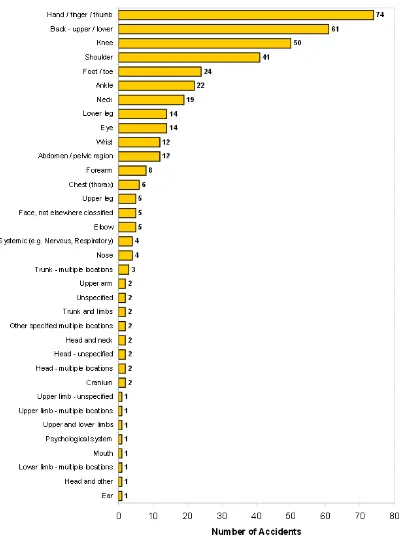
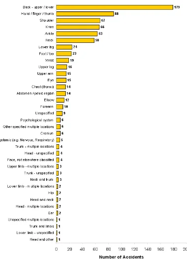
Figure 2-39: LTI - Body parts affected (DNRM 2013) ... 59
Figure 2-40: LTI - Body parts affected (DNRM 2013) ... 60
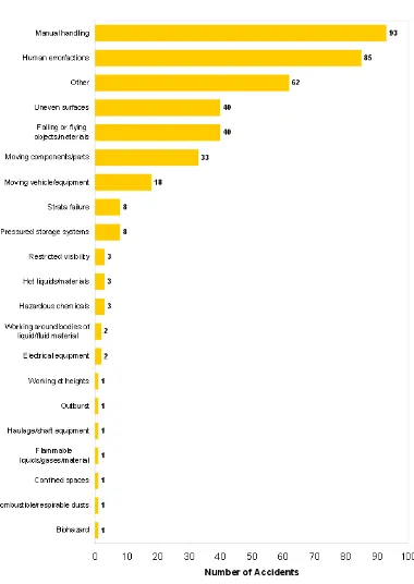
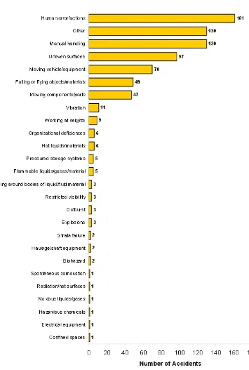
Figure 2-41: Hazards that cause LTI’s (DNRM 2013) ... 61
Figure 2-42: Hazards that cause LTI’s (DNRM 2013) ... 62
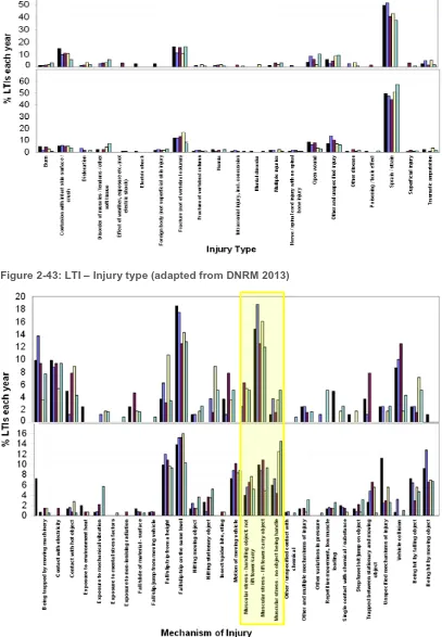
Figure 2-43: LTI – Injury type (adapted from DNRM 2013) ... 63
Figure 2-44: LTI – Injury mechanism (adapted from DNRM 2013) ... 63
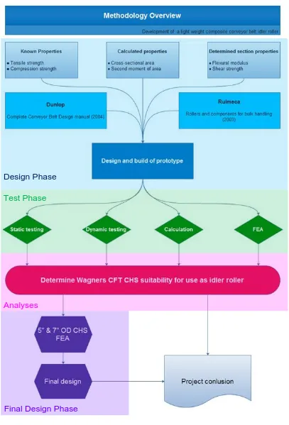
Figure 3-1: Methodology overview ... 67
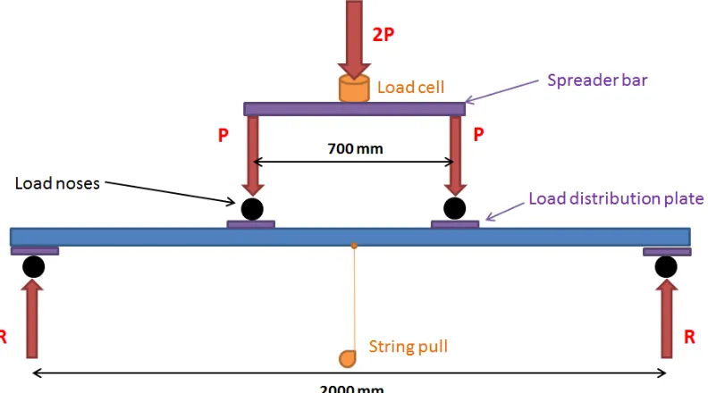
Figure 3-2: Four point bend test setup ... 68
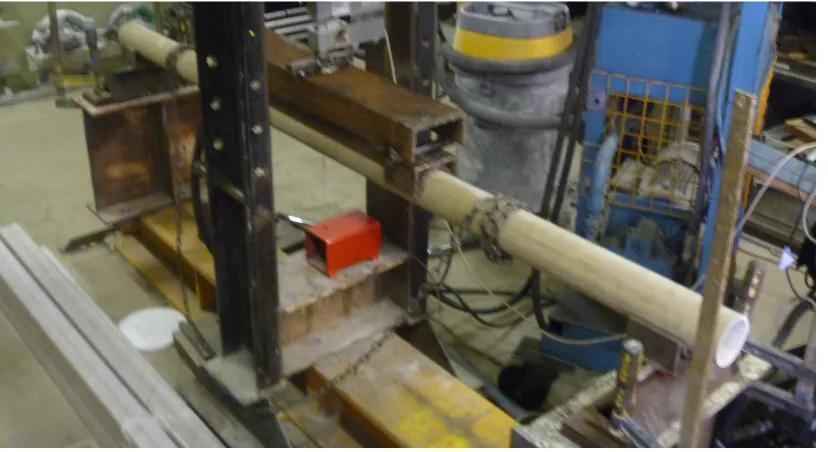
Figure 3-3: Actual four point test setup ... 69
Figure 3-4: Flexural modulus calculation spread sheet excerpt ... 69
Figure 3-5: Three point shear test arrangement ... 71
Figure 3-6: Actual shear test arrangement ... 71
Figure 3-7: Shear test spread sheet excerpt ... 72
Figure 3-8: Cross sectional view of a typical troughed conveyor (p. 35) ... 74
Figure 3-9: Dimensions around bearings (Juvinall&Marshek 2006, p. 573) 82 Figure 3-10: Full size hand drawn design sketch ... 83
Figure 3-11: ProEngineer prototype idler roller assembly... 84
Figure 3-12: ProEngineer exploded view... 84
Figure 3-13: Excerpt of detailed roller cap drawing ... 84
Figure 3-14: Top view of completed prototype roller ... 85
Figure 3-15: Angled view of built prototype roller ... 86
Figure 3-16: Prototype roller static proof test ... 87
Figure 3-17: Actual static prototype roller test ... 87
Figure 3-18: Schematic representation of fatigue jig ... 88
Figure 3-19: Fabricated fatigue rig ... 89
Figure 3-20: Fatigue rig assembled with roller ... 89
Figure 3-21: Motor mount and drive wheel assembly ... 90
Figure 3-22: Shaft constraint ... 90
Figure 3-23 Measure the roller rpm on operating fatigue rig... 91
Figure 3-24: Four point bend test meshed model ... 94
Figure 3-25: Four point bend test loading ... 95
Figure 3-26: Steel prototype shaft model... 95
Figure 3-27: Mesh refinements around shaft shoulders ... 96
Figure 3-28: Prototype shaft loading conditions ... 96
Figure 3-29: Static roller body model ... 97
Figure 3-30: Loading scenario on FEA model ... 97
Page | xi
Figure 3-33: Reduced load application width for dynamic test ... 99
Figure 4-1: FEA deflection results for P=10021N ... 101
Figure 4-2: FEA shaft deflection at P=1040N ... 103
Figure 4-3: FEA roller body deflection at P=1040N ... 103
Figure 4-4: Stress in modelled shaft at P=1040N ... 104
Figure 4-5: Stress in modelled roller body at P=1040N ... 105
Figure 4-6: Roller surface inspection ... 107
Figure 4-7: Close up of the area of belt contact ... 107
Figure 4-8: Microscopic view of area highlighted ... 108
Figure 4-9: Side view of fatigued roller ... 108
Figure 4-10: Failed shaft... 109
Figure 4-11: Expected cyclic stress on idler roller body ... 110
Figure 5-1: 5" OD CHS model ... 112
Figure 5-2: Loading conditions of the 5" OD CHS ... 112
Figure 5-3: Maximum deflection results ... 113
Figure 5-4: Maximum expected stress on idler ... 113
Figure 5-5: The meshed 7" OD CHS model ... 114
Figure 5-6: Static structural loads and supports ... 114
Figure 5-7: FEA deflection calculation ... 115
Figure 5-8: FEA stress results ... 115
Figure 5-9: Double row tapered roller bearing (NTN 2013) ... 116
Figure 5-10: Glass filled nylon bearing housing ... 117
Figure 5-11: Conceptual final shaftless idler design ... 118
Figure 5-12: Sectioned view of the assembled conceptual roller ... 118
Page | xii
List of tables
Table 2-1: Section properties calculations ... 37
Table 2-2: Known CHS properties (Skerman 2013) ... 37
Table 2-3: Number injury fatalities by injury mechanism (KWHSSA 2013).. 58
Table 3-1: Four point bend test result table ... 70
Table 3-2: Final Wagners CHS section properties ... 72
Table 3-3: Shear test results ... 73
Table 3-4: Excerpt of Table 2 (p. 10) ... 74
Table 3-5: Idler dimensions (p. 14) ... 75
Table 3-6: Maximum belt speed ( )(p. 15) ... 76
Table 3-7: Capacity of trough belt conveyors (ton/hour) (p.14) ... 76
Table 3-8: Recommended idler spacing (m) (p. 16) ... 77
Table 3-9: Belt mass (kg/m) (p.17) ... 77
Table 3-10: Dunlop design manual conclusion ... 78
Table 3-11: Principal operating factors ... 78
Table 3-12: Collection of factor tables ... 79
Table 3-13: Completed principal operating factors ... 80
Table 3-14: Rulmeca design calculations ... 81
Table 3-15: Dimensions around bearings (Juvinall&Marshek 2006, p. 573) 82 Table 3-16: Quotation results ... 85
Table 4-1: Four point bend test results for P=10021N ... 101
Table 4-2: Static test results for the design load of P=1040N ... 104
Table 4-3: Manual and FEA stress calculations results ... 105
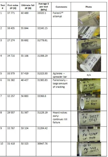
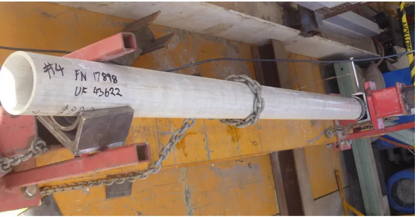
Table 4-4: Fatigue test log ... 106
Page | xiii
List of Appendices
Appendix A: Project Specification………...……… 128
Appendix B: Testing………129
Appendix C: Wagners SOP and SWI………...142
Page | xiv
Nomenclature and acronyms
ATM Accelerated Testing Method
ASTM American Society for Testing and Materials BMA BHP Billiton Mitsubishi Alliance
BMG Bearing Man Group
CFT Composite Fibre Technologies CHS Circular Hollow Section
CIDECT Dévelopement et l’Etude de la Construction Tubulaire CII Conveyor Innovations International
CMW Coal Mine Worker
DNRM Department of Natural Resources and Mines EPDM Ethylene Propylene Diene Monomer
FEA Finite Element Analyses
FEM Finite Element Method
FRP Fibre Reinforced Plastic
GOAF Ground Opposite Advancing Facing HDPE High Density Polyethylene
ISO International Standard Organisation JSEA Job Safety and Environmental Analysis
KWHSSA Key Work Health and Safety Statistics, Australia
LTI Lost Time Injury
MIG Metal Inert Gas
Mt Million tonnes
MW MegaWatts
Page | xv
PDF Portable Document Format
PPE Personal Protective Equipment
PU Polyurethane
PVC Polyvinyl Chloride
RHS Rectangular Hollow Section RPM Revolutions per Minute
SHS Square Hollow Section
SWA Safe Work Australia
TPH Tonnes per Hour
UHMW-PE Ultra-High-Molecular-Weight Polyethylene WCFT Wagners Composite Fibre Technologies WHS Workplace Health and Safety
Page | 1
Chapter 1
1
Introduction
The purpose of this chapter is to describe the project background, contextualise the industry from where this proposition originates, outline the project’s direction and highlight the research objectives of the project. This brief but comprehensive introduction is given to provide the reader with the basic information that applies to the author’s thesis, and to add a basic circumstantial framework to the author’s work.
1.1 Project topic
The development of a light weight composite conveyor belt idler roller for use in the mining industry
The primary purpose of this project was to investigate the prospect of a light weight conveyor belt idler roller constructed from pultruded continuous glass fibre, vinyl ester composite as produced by Wagners Composite Fibre Technologies (CFT).
1.2 Project background
Page | 2 1.2.1 Queensland coal mining operations
The Queensland Department of Natural Resources and Mines (2012) released a paper stating that ‘Queensland has a rich endowment of high quality coal resources, with more than 34 billion tonnes (raw coal in-situ) having been identified by drilling operations. They have identified resources of coking coal which amount to approximately 8.7 billion tonnes, of which about 4 billion tonnes are suitable for open cut mining’.
The annual coal production of 180 million tonnes (Mt) is mined by 43 open cut mines producing 154 Mt and 13 underground mines adding a further 26 Mt (Queensland Department of Natural Resources and Mines 2012). The Queensland coal industry exports approximately 116 million tonnes of metallurgical grade coal and 46 million tonnes of thermal coal per annum (Queensland Department of Natural Resources and Mines 2012).
Open cut mines are more common within Australia due to the operating costs of open cut mines being cheaper than underground mining. However, over half of the identified resources are suitable for underground mining. Therefore, an increase in the number of underground mines is expected.
Open cut mining 1.2.1.1
Open cut mining, also known as open pit or opencast mining, primarily mine by excavating from the surface. Rock covering the coal seam, the overburden, is blasted and removed by draglines, shovels and dump trucks. Open cut mines can reach depths exceeding 100m with modern equipment and technologies. Figure 1-1 illustrates a typical opencast mining pit.
Page | 3
Underground mining - Longwall mining 1.2.1.2
According to the Australian Department of Resources, Energy and Tourism geoscience division (2012) underground mining in Australia is usually performed by either the bord and pillar or longwall method.
In bord and pillar mining, coal is extracted through a series of parallel tunnels. Bords, cut at right angles by another tunnel series called cut-throughs, leave blocks of coal, known as pillars (Geoscience Australia 2012). In comparison, longwall techniques result in higher productivity and coal recovery rates due to the total extraction of larger blocks of coal whilst also allowing the mine roof to collapse behind the working face (Geoscience Australia, 2012). Longwall mines are created by driving two parallel underground roadways, known as headings, over 300m or more part, into the coal seam from the main travel road. The length of the block is determined by the individual mine requirements and geological conditions. The two headings are connected by a perpendicular heading called the installation road, as illustrated in Figure 1-2.
Figure 1-2: Simple longwall mine plan
Page | 4
Figure 1-3: Longwall shearer and chocks assembly (Joy Global 2012)
As the shearer advances the chocks follow in a snakelike pattern and the roof is allowed to collapse behind the chocks. The collapsed material is known as ‘ground opposite advancing face’ more commonly referred to as
GOAF.
As the longwall advances towards the main travel road, service lines such as water, electricity and the conveyor belts need to be shortened because the distance between longwall and the travel road diminishes.
1.2.2 Bulk material handling
Bulk material handling is the engineering field that predominantly deals with moving large amounts of dry material from one location to another, often from the mine site to a processing plant or from a processing facility to a transport mode such as ships or trains.
Today’s practises can be traced back through history. An early example of bulk material handling is a shaduf, used by ancient Egyptians to irrigate cultivations with water from the Nile River. Peterson (2006) explains that early modern bulk material handling started in the late 1700s, where human powered bucket conveyors or lifts we use to stack ships with primary produce. In 1804 the first steam powered conveyor was commissioned in a bakery as a time saving device, using cloth and leather as belting material (Todd 2008).
Page | 5 development of synthetic materials for belting (Peterson 2006), mainly due to the scarcity of natural materials such as cotton.
Today, bulk material handling systems incorporate a variety of machines such as screw conveyors or augers, stackers, reclaimers, rail cars, bucket elevators and the most common, troughed belt conveyors (McGuire 2009).
1.2.3 Conveyors
The Australian resource sector uses a large variety of high-capacity conveyors, with some systems boasting a 4 MW drive configuration with conveyor lengths in excess of 9 km and a rating of 5000 Tonnes per Hour (TPH) (ACE 2011). The basic definition of a conveyor belt is a system that contains two or more pulleys with the continuous loop of material, called the conveyor belt, supported by structural members that hold the pulleys in place, called conveyor structure (McGuire 2009).
Belting materials vary significantly depending on the application. Some of the materials commonly used includes cotton, canvas, Ethylene Propylene Diene Monomer (EPDM), leather, neoprene, nylon, polyester, polyurethane (PU), urethane, Polyvinyl Chloride (PVC), rubber, silicone and steel (Peterson 2006).
Conveyor belt anatomy 1.2.3.1
Page | 6
Figure 1-4: Conveyor Anatomy
Generally rollers between the drive head and tail pulley are known as idler rollers, with sub categorisation. The rollers directly below the feed chute (load point) are known as impact rollers. Impact rollers perform a very specific task with high intensity workloads.
Weight carrying rollers are known as carrying idlers or simply idler rollers. Rollers that support the belt on the reverse travel direction are known as returned idlers. Carrying idlers and returned idlers are the same rollers; however, the idler spacing is much larger for the return idlers as the load is only the weight of the belt itself. This project focused on the development of light weight composite carrying and return idler rollers.
1.3 Justification
This project emerged as a result of a call from Queensland mining giant, BHP Mitsubishi Alliance (BMA), to the conveyor industry. BMA was interested in finding a way of reducing the high number of manual handling related injuries that occur as a result of constructing, maintaining and disassembling conveyor systems.
Page | 7 encountered during construction, maintenance and disassembly of these conveyors.
Figure 1-5: Stacker tower
Page | 8 Conveyor stackers often tower hundreds of metres above the ground. The location and sheer height of these towers often mean that the conveyor is only accessible by the stairways and walkways constructed alongside the conveyor system. Therefore rollers must be manually handled by workers to their positions on the conveyor structure. This task often results in having to face obstacles such as steep ramps, stairs and gates.
Underground conveyor structures are often hung from the roof and due to a lack of space in the underground passages, they do not allow for any mechanical help. Therefore, people have to carry the rollers to their positions as well as manoeuvre the rollers into their individual fixtures. Structures often hang above head height and ladders are used to reach these overhead structures. This poses two significant problems: one, the person installing the roller has to carry the large heavy roller up the ladder and two, manoeuvring the roller often requires awkward body positions to be undertaken whilst on a ladder while the roller is placed in position. Figure 1-7 is an example of a suspended roller assembly.
Figure 1-7: Suspended roller assembly (Sandvik 2008)
Page | 9 1.3.1 Hierarchy of control
Justifying the project using engineering hierarchy of control according to ISO 9001 – Quality systems:
Figure 1-8: Hierarchy of control (Quality Systems Toolbox 2013)
The top three control strategies (elimination, substitution and engineering) are known as engineering controls and should be implemented, where possible, because they are less subject to human failure (Quality Systems Toolbox, 2013).
Elimination is the best control measure; however, elimination is not possible in the coal industry especially underground mining. The coal must be transported from the mine to the mode of transport.
Substituting conveyors with trucks is possible. This would be a very expensive change and the increased vehicular traffic may introduce new risks of significant magnitude.
Engineering control can be introduced by making changes to the equipment to reduce the hazards. This is a suitable control. Engineering new rollers with a significant reduction in weight can substantially reduce the hazard of manual handling injuries.
1.3.2 Conclusion
Page | 10
1.4 Composite materials
A composite material is created when two or more distinct materials, that do not merge, combine to create a superior and unique material with properties resulting from the combination of their individual attributes (Johnson 2013). Johnson (2013) suggests that by combining mud and straw, the ancient Egyptians produced their own primitive composites that they used to create strong buildings. The success of the conqueror Genghis Khan, during the 1200s, can be attributed to the military dominance given by the powerful and accurate composite Mongolian bows, which were constructed using bamboo, sinew and animal horn.
However, modern composites owes its origins to salesperson Owens Corning that originally developed fibre reinforced polymers for use as insulation material in 1935 (Strong 1995). The anisotropic nature of the fibrous material was soon discovered and the development of structural products followed shortly.
Composite materials have proven to be the prime choice in extreme performance applications, such as the aerospace and nautical industries, as well as high corrosion environments. Attributed to the benefits of high strength to low weight ratio, extreme corrosion resistance and long service life, composite materials’ acceptance by engineers has greatly increased in recent years.
1.5 Wagners Composite Fibre Technologies
Wagners CFT fabricates structural grade composite sections, both Rectangular Hollow Section (RHS) and Circular Hollow Section (CHS), using continuous glass fibre and vinyl ester resin in a pultrusion process. Wagners CFT is a world leader in research and development. They design and implement Fibre Reinforced Plastic (FRP) solution for specialty applications reaching into areas such as marine infrastructure, road infrastructure, timber bridge rehabilitation, pedestrian infrastructure and electrical industry solutions.
Page | 11 new FRP products. The underlying support to new product research sets the scene for Wagners CFT’s involvement in the development of light weight composite conveyor belt idler rollers.
All Wagners CFT sections are pultruded continuous glass fibre, vinyl ester composites. This poses a significant challenge with regards to idler roller design. Traditional idler rollers are moulded or die cast with sections included for bearing houses. Continuously pultruded sections do not have this capability as the process only produces the CHS. The design must incorporate bearing housing location and method of attachment.
1.6 Project Aims and Objectives
The deliverables of this project have been carefully composed to fulfil the requirements of ENG4111/4112, and because it is an industry based project, also the objectives of Wagners CFT. The research aims and objectives are an extension of the project specification that can be found in appendix A. This project endeavours to investigate the prospect of developing a light weight composite conveyor belt idler roller for use in the mining industry constructed from pultruded glass fibre vinyl ester composite as produced by Wagners CFT.
The project objectives are to:
Research and investigate current idler rollers technologies used in conveyor belts
Define Wagners CFT CHS composite and determine required section properties
Review literature pertaining to composite’s performance in fatigue Investigate issues with conveyor belt systems in the Australian mining
industry with particular interest in conveyor belt system related injuries during installation, maintenance and decommissioning through case studies and Workplace Health and Safety statistics
Define problem and need for research
Develop methodology for the development of a light weight composite idler roller
Conceptually design possible idler rollers and choose prototype design. Substantiate prototype design by recognised mechanical engineering methods
Page | 12 Evaluate design. This will be achieved by mechanical laboratory static
and fatigue testing, mathematical calculations and Finite Element Analysis
Analyse results from various tests and determine suitability of belt idler rollers shell constructed from pultruded glass fibre vinyl ester composite Conceptualise final design
Make recommendations and suggest further studies.
1.7 Concluding remarks
Page | 13
Chapter 2
2
Literature Review
A review of appropriate literature pertaining to modern conveyors systems including current non-ferrous idler rollers, composite materials and Occupational Health and Safety (OHS) is presented and discussed in this chapter.
2.1 Conveyors
The most common material handling conveyor in use today is the belt conveyor (McGuire 2009). Belt conveyors are the least expensive powered conveyor (ACE 2011) with the capability and capacity to carry almost all raw materials from grain to iron ore (ACE 2011). Belt conveyors generally carry materials over long distances and use anywhere from one to ten drive stations depending on the length (McGuire 2009). For the purpose of this project, literature with respect to current conveyor technologies, including the common ferrous idler rollers and roller design methodologies, was reviewed. 2.1.1 Current conveyor technologies
Page | 14
Figure 2-1: Simplified troughed belt conveyor (McGuire 2009, p. 63)
Figure 2-2: Pipe conveyor (McGuire 2009, p. 66)
Page | 15
Figure 2-3: Simplified belt conveyor system
Figure 2-4: Belt conveyor drive head (Nordstrong 2013)
Page | 16 Other modern drive systems include belt-driven live roller, lineshaft and motorised rollers. These systems rely on the rollers to support and transport the payload (McGuire 2009).
The selection criteria and selection process for installation of belt conveyors is a very intricate procedure that deals with a complex interweaving of conveyor system capacities, technological options and specified objectives. Major conveyor belt supply companies, such as Dunlop, Rulmeca and Sandvik, produce large documents, called design manuals, with the purpose of assisting engineers to select the most appropriate option for their requirements. The design manuals guide engineers step by step through all of the design considerations that should be assessed. All of the manuals contain a section that deals with idler roller selection. This is discussed in more detail in roller design methodology (Section 2.1.3).
All belt conveyors require rollers to support the load, guide the belt and provide the belt shape regardless of the configuration. The number of idler rollers required by each conveyor depends on a multitude of different criteria such as length of conveyor, material characteristics, required capacity, belt speed and terrain (Dunlop 2004).
2.1.2 Idler roller technologies
As the conveyor industry technology develops, idler technology must develop to keep up with modern design requirements and standards. While the belt conveyor is the most common bulk material handling conveyor in use today (McGuire 2009), all belt conveyors require idler rollers to support the payload between the drive head and tail pulley. Idlers can be reviewed with many general factors like noise emission, vibration, material composition, corrosion resistance, performance, size, speed reliability, weight and many others.
The purpose of this project is to develop a light weight composite roller. Therefore the idler technologies was reviewed under sub sections of ferrous and non-ferrous with a strong emphasis on weight, performance and construction with minimal consideration given to cost. The following factors was used as a guide of characteristics to be considered:
Shell/roller body
End cap/end plate/bearing housing Bearing
Seals
Page | 17 The roller shell is the heaviest part of the idler (Haines, 2007; McGuire, 2009) closely followed by the shaft. The rollers reviewed as part of this project were a selection of commercially available rollers and the review of these is focused specifically on comparing shell and shaft design.
Ferrous Idler roller technologies 2.1.2.1
2.1.2.1.1 Rex Idlers
Page | 18
Figure 2-6: Rex Roller (Rexnord Corporation 2013)
2.1.2.1.2 RKM Roller Company PTY LTD
RKM Roller Company mass produces standard high performing rollers for mine and port structures. The roller body is rolled from electric-resistance-weld ERW 200 -350 tube utilising plain steel. The end housing grooves are precision machined to ensure eccentricity. The end housing discs are pressed into the required shape and welded into place with an autonomous welder, placing a 3 mm fillet bead at the junction. All rollers are fitted with single row deep groove ball bearings with C3 internal clearance. The bearings are factory greased for life with Lithium based grease. Starting from the inside, the various protective elements are:
a rear seal fitted to protect the bearing from mill scaling and any inherent contaminate,
a triple labyrinth female seal, a triple labyrinth male seal, a dust trapping steel cover,
Page | 19 The shaft consists of solid cold drawn mild steel round bar that is machined to seat components. RKM rollers, as seen in Figure 2-7, are cheap and suit most general purpose applications but the steel construction is heavy.
Figure 2-7: RMK idler roller exploded (RMK 2012)
2.1.2.1.3 StrongFlex
Page | 20
Figure 2-8: RollKing ilders and idlers ready for transport (StrongFlex 2011)
2.1.2.1.4 Fenner Dunlop
Page | 21
Figure 2-9: Fenner Dunlop idler (Fenner Dunlop 2013)
2.1.2.1.5 Sandvik Mining
Page | 22
Figure 2-10: Sandvik idler arrangement (Sandvik 2011)
2.1.2.1.6 Bearing Man Group Belting
Bearing Man Group Belting is a subdivision of Bearing Man Group (BMG), a South-African company, which primarily deals with conveyor supply, technical advice and service. BMG Belting developed a distinctive conveyor idler system that utilises steel three-idler-roller 35° trough load carrying configuration with flat HDPE return idlers as depicted in Figure 2-11.
Figure 2-11: BMG Belting system (BMG Belting 2010)
Page | 23 bearings perform for the life of the roller. The front seal is a labyrinth with a complex path to inhibit the entry of debris. A cover is used as a primary defence barrier to deter moisture and dust. The shaft is made from solid steel for both the steel and HDPE shell variations. BMG Belting uses standard idler rollers in an efficient manner to produce a very effective conveyor system with low rolling resistance and maintenance. Figure 2-12 shows the top layer of a packed steel idler roller pallet in storage.
Figure 2-12: BMG Belting idlers (BMG Belting 2010)
2.1.2.1.7 Rulmeca
Page | 24 advanced seal system in the idler industry. The spindle is made from hard high carbon steel with a h6 or g6 fit.
Figure 2-13: Rulmeca PSV idler exploded view (Rulmeca 2012)
Rulmeca PSV idlers are the world most commonly used roller for both its reliability in operation and economical cost. These rollers are produced with a goal of long service life and no material is spared, making these rollers very heavy. The non-ferrous rollers consider weight and therefore, are much lighter. A cut-away view of the packed Rulmeca PSV idler roller can be seen in Figure 2-14.
Page | 25
2.1.2.1.8 Conveyor Innovations International
Page | 26
Figure 2-15: Shaftless OneFits half cut view ( CII 2013)
Page | 27
2.1.2.1.9 Ferrous idler remarks
The shell or body of most ferrous rollers are manufactured from mild steel tube. CII developed a purpose-specific alloy to use in the shaftless idler design, Vitresteel, to create a light and strong roller. Certain manufacturers turn the body to ensure eccentricity and close tolerances. All rollers are rounded at the ends to ensure no sharp exposed edges will cut belts. A significant amount of manufacturers MIG weld the turned end caps into place using a groove to position the plate. A few companies press the end caps. Only one company (Rulmeca) uses a singular CHS construction that is hot and cold worked into shape. The CII idler has a uniquely designed bearing housing that is a tightly packed unit that can withstand large moments. This housing also serves as the end cap. With the exception of Rex Roller’s single row tapered roller bearing and CCI’s double row tapered roller bearings, all remaining idlers contain radial single row deep groove ball bearings with a C3 internal clearance. Bearings can be factory sealed or regreasable depending on the application. Low to medium duty bearings are normally factory sealed-for-life whilst medium to heavy duty applications require regreasable bearings. An added benefit of regreasble bearings is the fact that the bearings and seals get flushed with as clean grease replaces the old soiled grease. Labyrinth seals are standard for most idlers with the exception of proprietary self-cleaning seals by Fenner Dunlop. Commonly solid mild steel shafts or spindles are used to support the rollers. These shafts are machined and often plumbed with grease lines. Particular manufacturers utilise hollow shafts on the return non-payload carrying idlers. Some heavy duty idlers can use high carbon steels for added strength. CII OneFits are currently the only shaftless rollers commercially available.
Non-ferrous Idler roller technologies 2.1.2.2
2.1.2.2.1 Glide seal idler roller
Page | 28
Figure 2-17: Glide seal roller (Glide seal 2009)
The Glide seal roller uses ball bearings that are grease filled and sealed for life. The bearings are protected from the elements by an inbuilt labyrinth. The shaft is made from high carbon steel to withstand the operational stresses of an idler roller. The light weight version of the idlers, used in belt return applications, features a hollow central shaft design. Glide seal rollers are currently installed on ship-loader equipment around Australian ports. The benefits of the light weight shell and polymeric bearing housing gives Glide seal rollers a very light setup, however, aluminium metals are not permitted on most surface mines and contraband in underground mines.
2.1.2.2.2 StrongFlex HDPE and UHMW-PE rollers
Page | 29
2.1.2.2.3 Fenner Dunlop
Fenner Dunlop produces a polyurethane (PU) idler that is starting to trend within Australia especially with informed decision makers. PU is a thermoset polymer composed of organic units and carbamate (urethane) chained together (Ionescu 2005). The patented PU shells are made in a range of sizes and wall thicknesses: Ø102mm x 12mm, Ø127mm x 12mm and Ø152mm x 17mm. The PU idler has a distinctively designed endplate and bearing housing that claims to increase bearing life by absorbing shock loads. This arrangement, as shown in Figure 2-18, combined with sealed single row bearings, produces a low friction and highly efficient idler, unsurpassed by any other non-ferrous roller currently available.
Figure 2-18: Fenner Dunlop Polyurethane idler (2013)
The seal is a four-rake press fit seal as based on Figure 2-18. (This is only an educated deduction as the arrangement is confidential). The PU idler rollers are 50% the weight of the steel rollers and are manufactured to a very high standard.
2.1.2.2.4 Rulmeca
Page | 30 Figure 2-19, is made by an injection moulding process from homopolymer acetal resin.
Figure 2-19: Top Roller cut away (main) and insert details (Rulmeca 2012)
This is seated in the tube for the correct alignment of the bearings and spindle. The only non-thermoplastic components are the bearings and solid shaft. The bearings are chosen from the same series of bearings as the Rulmeca steel idler series. The bearing is triple sealed for ultimate protection. One internal seal is used behind the bearing and two seals, lip and labyrinth, are used to protect the front. As with all Rulmeca idlers, a stone guard protects the seals. Top Roller idlers weigh about half the weight of ordinary steel idlers. The idlers vary from 89mm to 133mm diameter with wall thicknesses of 9mm to 11mm. The maximum length that Rulmeca currently produce is 538mm due to the lower modulus of rigidity of HDPE compared to steel.
2.1.2.2.5 Blue King Rollers
Page | 31 steel rollers in weight carrying capacity and wear resistance. An additional benefit to the Blue King roller is that the HDPE material does not allow adhesion of processed material which is the primary cause of belt miss-tracking, spillage and leakage. The roller is moulded into the required shape and therefore includes the end plate and bearing housing with no additional manufacturing necessary as shown in Figure 2-20. The bearings are double capped bearings that are factory greased and sealed. The addition of the labyrinth seal further protects the bearing from foreign material influx and ensures long maintenance free service life. The shaft is manufactured from mild steel and provides the structural backbone for the roller. Aktiv claims to be 50% lighter than any steel roller of respective function and size. Blue King rollers contains an anti-static agent preventing charge build up which makes these rollers suitable for grains storage, flour mills and underground mining. Blue King Roller is an excellent roller system with great weight savings even though it uses a solid steel shaft.
Figure 2-20: Blue King Rollers breakdown (Aktiv 2008)
2.1.2.2.6 Yeloroll
Page | 32 shells are fabricated from a titanium modified PVC that features excellent abrasion resistance with light weight. The endplate and bearing housing are manufactured by means of precision injection moulding from a durable nylon glass fibre composite with an antistatic copper pin. Factory sealed deep groove ball bearings with C3 clearance are used in a sealed for life arrangement. Bearing sizes currently used include 6204, 6205, 6306 and 6308. The bearing is protected by a bearing seal that is watertight and dust resistant as well as a reverse multi labyrinth seal. The shafts can be made from either mild steel or stainless steel, depending on the application and a protective can be used in conjunction with either mild steel or stainless steel to ensure no exposed steel parts can rust. Idlers are made with roller diameter sizes of 114 mm to 178 mm with the shaft sizes ranging from 16 mm to 40 mm. These idlers are up to 4.4 dB (A) quieter than steel idlers, this is a noise level less than half the intensity. The PVC body and nylon glass fibre bearing housing produce a roller that is 60% lighter than the same size steel roller. Yeloroll offers quieter, lighter, anticorrosive, self-cleaning and belt friendly rollers that can outperform most steel rollers in heavy duty applications.
Figure 2-21: Yeloroll idler half roller cut away (Yeloroll 2012)
2.1.2.2.7 Non-ferrous idler remarks
Page | 33 compared to steel idlers. This is mainly due to the relatively new development of non-ferrous idlers and the costs of different grades of polymers. Materials used in the body ranges greatly and the various constructions include aluminium, UHMWPE, PU, PVC and most commonly HDPE. The end caps and bearing houses from various products are produced from polymeric inserts, PU, homopolymer acetal resin, HDPE and glass filled nylon with an antistatic copper pin. All of the investigated idlers use radial single row deep groove ball bearings with a C3 internal clearance. Four types of seals can be found in non-ferrous rollers: labyrinth, reverse labyrinth, four-rake press fit seals and a lip and labyrinth arrangement. Shafts are all made from mild or stainless steel with light duty rollers containing hollow shafts.
Final Remarks 2.1.2.3
Although non-ferrous rollers are not as poplar or versatile as steel rollers, there is an increasing demand for non-ferrous rollers in the industry. The industries that prefer non-ferrous rollers are usually in corrosive environments, such as companies on coastlines or manufacturers that handle corrosive materials like salt. Other companies that are interested in light weight rollers are mines with stacking towers or underground mines. The polymer roller industry can currently produce rollers up to 535mm in length and various diameters. The call for larger, light weight rollers (such as 1200 mm in length and 150+ mm diameters) in the market remains unfulfilled.
2.1.3 Roller design methodology
Large conveyor design and construction companies typically produce large documents, called design manuals, to assist engineers to design and specify conveyors to satisfy their needs. A brief overview of the three design manuals reviewed for this project is shown below. These three manuals were chosen because the publishing companies are the world leaders in their field with a significant presence in Australia. These include:
Sandvik – HA200 Idlers design manual (2008)
Rulmeca – Rollers and components for bulk handling (2003) Dunlop – Complete Conveyor Belt Design manual (2004)
Page | 34 arrangements. The last section is a complex set of graphs and figures to decide belt size, speed and driving requirements.
Rulmeca – Rollers and components for bulk handling (2003) is a complete guide to conveyors and conveyor systems from design right through to implementation and maintenance. This free downloadable PDF, available from www.rumeca.com, describes the roller design, loading design and mathematical calculations in great detail in all sections of the design steps. Chapter 2 of the document deals specifically with rollers. The selection process is based on the roller diameter, revolution per minute and belt speed. The next section describes required operation factors and loading circumstances. The roller loading determination section is dedicated to calculating the load on a single roller at full capacity (Rulmeca manual, p. 75-79). This set of calculations was very useful and used in the methodology chapter that deals with roller design. The final section of the Rulmeca manual overviews selection of Rulmeca rollers based on the outcomes of the calculations.
Dunlop – Complete Conveyor Belt Design manual (2004) is the metric version of two manuals based on imperial (written and published in the USA) and metric units. The gratis PDF, published in South-Africa and available from www.fennerdunlop.co.za, is a complete guide to conveyor belting that aligns with the South-African, New Zealand, Australian and International Standard Organisation (ISO) standards. This makes the document applicable in Australia and globally. The document uniquely approaches the design based on the bulk materials, material properties and required flow capacity. The entire design manual is based on tables such as material properties, capacities of belts, belt speed and idler spacing. All the tables are intrinsically interlinked with no required starting point. It means that the design can be started from any known parameters and the interlinked tables will guide the user to a final design. The process is less structured than any of the other approaches, but allows for much greater diversity and choice. This document was the ideal guide for this project as the material and roller diameter were the only known parameters, and there was no interest to select an existing roller. The tables and pathway used is discussed in much greater detail in section 3.1.2.
Conclusion 2.1.3.1
Page | 35
2.2 Composite Materials
2.2.1 Wagners Structural Composites
Wagners produces a range of structural grade composites for use in corrosive environments and in applications where light weight and extreme durability is crucial, such as cross arms for the utilities network. The three main products produces by Wagners are 100 mm x 100 m (5 mm thickness) Square Hollow Section (SHS), 125 mm x 125 mm (6 mm thickness) SHS and 100 mm x 75 mm (5 mm thickness) RHS. Variations of the sections are shown in Figure 2-22.
Figure 2-22: Various Wagners SHS and RHS products
Wagner CFT CHS 2.2.1.1
Page | 36
Figure 2-23: Wagners CHS
Section properties as calculated using Australian Standard AS 1163-1991 (1991) can be found in Table 2-1. The Australian Standard AS 1163-1991 is based on the Comité International pour le Dévelopement et l’Etude de la Construction Tubulaire (CIDECT) (1984), Construction with Hollow Steel Section. Figure 2-24 shows the simplified CHS cross-section.
Page | 37
Table 2-1: Section properties calculations
Cross-sectional area ( )
Mass
Perimeter of cross-section
External surface area
Second moment of area
( )
Section modulus
Radius of gyration √
Known section properties are tabulated in Table 2-2 (Skerman 2013).
Table 2-2: Known CHS properties (Skerman 2013)
Axial tensile strength >400 MPa
Axial compression strength >400 MPa
Hoop tensile strength 300 MPa
Poison’s ratio (material property) 0.3
Wagners CFT are currently developing more pipe sizes that will be suitable for mining idler rollers including 5” OD (127 mm) and 7” OD (178 mm) pipes with wall thicknesses of 8 mm and 10 mm respectively. These sizes was analysed and considered for the design and final suitability statement.
Wagners CFT proprietary thread and bonding systems 2.2.1.2
Page | 38
Figure 2-25: Wagner Wedge
2.2.2 Determination of section properties
Many different testing regimes can be used to determine material properties. The two major types of testing are destructive and non-destructive (Norton, 2013). Non-destructive testing involves applying a predetermined load and recording the displacement to ensure that the specimen can tolerate the load. This testing only provides information within the operational limits and is mostly used in quality assurance procedures (Intertek, 2013). Destructive testing comprises of applying a constantly growing load onto a test specimen until the specimen fails. Destructive testing provides information regarding operational behaviour, as well as maximum strength properties (Norton, 2013). Destructive testing delivers the most useful information and suits the purposes of this project.
Page | 39 ASTM D790-10 describes the three point loading system applied to a simply supported beam. However, the test is only valid if the specimen breaks in the outer surface. Pultruded CHS is hollow, posing a significant danger of a localised crush failure occurring below the single load point in a three point bend test. Initial test trails, as performed by Wagners CFT, showed that a three point bend test does not consistently fail in the outer layers of the pipe. The scope for ASTM D790-10 highlights that ASTM D6272 describes a four point loading system applied to a simply supported beam as an alternative for non-complying test specimens. The major difference between the three point and four point flexural tests is the location of the bending moment. The four point bending method allows for uniform stress distribution between the two loading noses, whilst the three point bending method’s stress is located under the loading nose (Intertek, 2013). Nordson (2013) believes performing four point bend tests hold serendipity. The test produces the peak stresses over a larger length of the specimen, giving more potential for flaws and defects to be highlighted. Therefore, the four point bend test is more suitable for this study. The modulus of elasticity can be determined by using the four point bend test.
Flexural properties standard test method ASTM D6272-10 2.2.2.1
The standard test method pertaining to both semi-rigid and rigid materials for plastics and composites, is the determination of flexural properties. This section highlights information of relevance to this project.
Page | 40
Figure 2-26:The loading diagram options as illustrated in ASTM D272
ASTM D6272-10 (p. 12) states ‘the loading noses and supports shall have cylindrical surfaces’ as illustrated in Figure 2-27. In order to avoid stress concentration or indentation, directly above the supports or below the noses, flat plates may be used at these regions (ASTM D6272-10). The deflection measuring device must be automatically continuously recording the deflection as well as the corresponding load (ASTM D6272-10).
Figure 2-27: Test setup as shown in ASTM D6272-10
The number of specimens required for isotropic materials is five; anisotropic material is five in each direction or 10 in the direction of interest. The modulus of elasticity can be calculated for the one third load span by using the following formula (ASTM D6272-10):
Page | 41 Where modulus of elasticity in bending, MPa
support span, mm
width of beam tested, mm depth of beam tested, mm
slope of tangent to the initial straight line
This calculation method requires further calculation from measured deflection. However, using this test, a theoretical approach can also be used to calculate the modulus.
Flexural strength mathematical theory 2.2.2.2
The deflection can be calculated at the centre using the principles shown by Beer et al. (2006). Consider beam AE, in Figure 2-28, simply supported at both ends with two equal loads symmetrically placed.
Figure 2-28: Four point bend test (Beer, Johnston & DeWolf, 2006)
Now consider portion ABC only and use symmetry about C Reactions:
[ ] [ ] [
]
[
]
For
Page | 42
For
Use boundary conditions to solve constants
[ ] →
[ ] →
[
]
[ ] ( )
For deflection at point C, set :
( )
( )
( )
Page | 43
Equation 2-1: Calculation of modulus of elasticity
( )
where
( )
( )
Shear properties standard test methods 2.2.2.3
There are multiple ASTM standards that deal with tests to determine shear properties such as ASTM D7078, D5379, E1876-09 and C273. These tests are not suitable for composite hollow section as they are designed for resin-only samples, V-notched samples or honeycomb sandwich laminates. The properties of the CHS can be found using the CIDECT based document,
Steel construction, (Syam, 1992) in accordance with AS4100-1990.
Shear strength test in accordance with AS4100-1990 2.2.2.4
The shear test is set up with the same support and loading conditions as ASTM D6272-10. ASTM D6272-10 (p. 12) states ‘the loading noses and supports shall have cylindrical surfaces’. Flat plates may be used at these regions to avoid stress concentration and the deflection measuring device must be automatically continuously recording the deflection and the corresponding load (ASTM D6272-10). The 10 sample must be tested in the direction of interest.
The test can be set up as shown in the schematic, Figure 2-29, as prepared by Syam (1992). Section 3.1.1.2 elaborates on the test method in more detail. Syam further declares that the maximum shear stress can found using in the setup of Figure 2-29 and Equation 2-2 as long as a<b:
Equation 2-2: Maximum shear stress
Page | 44
Figure 2-29: Simple beam - concentrated load at a point (Syam, 1992)
A minimum of 10 specimens must be subjected to destructive testing.
Three point bend test 2.2.2.5
Page | 45
Figure 2-30: Uniform mid-span load (Syam 1992)
The maximum deflection can be calculated using Equation 2-3 when :
Equation 2-3: Maximum deflection
( )
A minimum of 10 tests was performed to ascertain adequate deflection and load carrying capacity data. This data was analysed and the extracted information was used to validate the FEA models.
Finite Element Analysis 2.2.2.6
Page | 46 (1986) suggest that properties of anisotropic materials can be ‘smeared’ into an average value and used for computation as long as the investigation does not involve a specific failure method. Thus, the calculated values from the physical testing can be used to analyse composite materials as long as the material does not approach the point of failure.
2.2.3 Fatigue behaviour and fatigue modelling of fibre composites Since fibre composites are a relatively new mass produced product, very few industry guidelines exist. Although researchers have studied fibre composites for an extended period of time, no standardised methods and models have been identified to investigate the fatigue behaviour of composites. The literature reviewed considers briefly how fibre composite fails, the methods used to monitor these failures, models used to predict failure and possible applications for fibre composites with high fatigue strength.
It has been suggested that ‘One of the unique characteristics of fibre-reinforced composites is that their properties can be tailored to meet different types of loading conditions... even fatigue’ (Askeland and Phule, 2008, p. 627). Yu et al. (2011) and Lewis and Gagg (2010) both produced detailed reports of investigations of the performance of glass fibre composites in fatigue and believe that composites have a very high fatigue strength in most cases. Contrary to these findings, Grimmer and Dharan (2008, p. 4488) state that ‘[g]lass fibre polymer composites have high strength, low cost, but suffer poor performance in fatigue’. Grimmer and Dharan (2008) believe that energy absorbing additives need to be added specifically to raise fatigue strength. The ambiguity regarding the fatigue strength of composites may be a direct result of unclear industry guidance relating to this topic. ‘Fatigue crack propagation behaviours for composites have still not been standardized’ (Ferreira et al. 2010, p. 3547). This uncertainty leads to the investigation of current practices in determining the fatigue strength of composites.
Page | 47 and suggest that a large portion of defects that affect the fatigue behaviour are defects caused during manufacture, either highly concentrated resin areas, or poorly penetrated fibre areas. The ASM handbooks online (2003, p. 1032) also state ‘Fatigue cracks can initiate from porosity in composites’. In order to fully understand exactly how fibre composites fail, researchers continuously come up with new fatigue monitoring techniques (Japan Carbon Fibre Manufacturers Association 2009). One of the most advanced monitoring techniques currently in use was developed by Limin et al. (2010) and uses strategically placed conductive nanotubes to quantitatively measure the accumulated damage. According to Limin et al. (2010, p. 4088) ‘Various damage stages in composite cross-ply laminates under fatigue loading can be clearly detected by adopting the quantitative parameter, damaged resistance change’. Another suggested method is to produce a specimen with a specific change in geometry as to induce a stress concentration region and uses multi-directional strain gauges to monitor elongation. This gives the researcher data to calculate the direction of principal stresses and maximum shear orientations (Tech note, Intertechnology 1995 and Composites Australia 2012). However, Abdullah et al. (2009) believe that trends in experimental results can be used to evaluate the failure type.
Experts in the field have devised many different models in order to predict fatigue failure. Pupurs and Varna (2011) has developed their own model based on Paris Law that uses an analytical solution to modeI energy release rate to predict failure in long debonds. For short debonds, Pupurs and Varna (2011) suggests FEM modelling in conjunction with the virtual crack closure technique. Zhifei et al. (2008, p. 2248) developed a method of using commercial Finite Element Analysis (FEA) packages and incorporating the energy release rates utilized in Paris Law to approximate the fatigue damage of fibre reinforced composites in fatigue. Andersons and Paramonov (2011) ‘believe the most accurate method of fatigue life estimation… is by the modified Goodman diagram’ (p. 1708).
Page | 48 Despite the ambiguity regarding the fatigue strength of fibre composites, many researchers suggest that adding fibre composite materials to structural applications will greatly increase the fatigue life of these components. NASAeClips (2010) believes that composites are the future material for all applications. ATL composites Australia (2011) uses composite marine frames in the ocean where there is no shortage of fatigue and Abdullah et al. (2009, p. 44) claims that fibre metal laminates significantly improves the fatigue life of light weight aerospace structure. This statement is greatly supported by Eurofighter Jagdflugzeug (2012). Botelho et al, (2008, p. 3166) agrees with the advantages regarding fatigue life by using composites in aerospace structures but raise their concern with the reparability of composites.
‘Due to the high fatigue strength of composites’, Yu et al. (2011, p. 558) suggest that ‘introducing composites into concrete can significantly improve the fatigue life of concrete beams in structures’. This statement is supported by self-devised experiments by the authors.
Whilst reviewing literature for this project, other factors, not discussed in detail in the previous section, became apparent. These factors include, but are not limited to, the thermal environment (Bettini et al. 2011and Manjunatha et al. 2010 and Mivehchi & Varvani-Farahani 2010), the over usage of filler materials (Bettini et al. 2011and Ferreira et al. 2010), additives such as nanoparticles and carbon nanotubes (Bettini et al. 2011and Limin et al. 2010), surface conditions (As per book MEC3203, 2012 and MEC1201, 2009) and different cyclic loading cases (Jung-Hun et al. 2010, p. 2615 and van Paepegem and Degrieck 2004)
Fibre composite materials are becoming more commonly used and better understood than ever. Many researchers use well known methods like the Goodman diagram and models such as the Paris Law or Puck’s Criterion to evaluate the fatigue failure modes, fatigue strength and fatigue characteristics of fibre composites. While each of the methods and models carry individual merit, a general consensus leans toward the need for a standardization of failure models and fatigue prediction models to be constructed. Although some claim that fibre composites have poor fatigue life and low fatigue properties, most research suggests that composites are very good materials to use in highly cycled applications.
Page | 49
2.3 Occupational Health and Safety
The Australian Government Department of Education, Employment and Workplace Relations originated the Work Health and Safety Bill in 2011 that was adopted as the Work Health and Safety Act in 2011(ComLaw, 2011). This act relates to work health and safety, and for related purposes. ComLaw (2011) describes that the main purpose of this act ‘is to provide for a balanced and nationally consistent framework to secure the health and safety of workers and workplaces by:
(a) protecting workers and other persons against harm to their health, safety and welfare through the elimination or minimisation of risks arising from work; and
(b) providing for fair and ef