University of Southern Queensland
Faculty of Health, Engineering & Sciences
Make Garfield (6 axis robot arm) Smart
through the design and implementation of
Voice Recognition and Control
A dissertation submitted by
Kyle Tonkin
in fulfilment of the requirements of
Course ENG4111 Research Project part 1 & ENG4112
Research Project part 2
Towards the degree of
Bachelor of Electrical Engineering
ABSTRACT
The Voice is a powerful tool used in everyday life. It expresses our feelings, emotions and is unique to every individual. Developing a system to decipher its functionality and deal with the complexities involved in its digitalisation, becomes quite the task. Once harnessed, it has the potential to become one of the most popular methods of control throughout the world. Garfield (a 6 axis robotic arm) is in need of an extra method of control that can essentially make it ‘smarter’. In trend with current popularity, Voice Recognition has been selected as the method for control and the processes taken to implement such a system are explored in the following dissertation. Its outlines the design, development and implementation of a working voice recognition system used in conjunction with robotic arm software. In essence, this project explores the application of such a technology to the industrial robot industry and tests its performance as a whole.
A signal processing methodology was investigated, designed and developed in order to implement the voice as a control tool on the robotic system. This included the research and development of a voice detection algorithm based on the principles of voice recognition and required integration with robotic control software to execute appropriate movement.
Existing literature was explored in order to understand and apply the concepts of voice recognition and integrate it into a system responsive to user utterances. The basic outline of the processing techniques used followed those involved with Mel Frequency Cepstral Coefficients (Kumar & Rao 2011) and the recognition techniques involved with Euclidean distances (Muda, Begam & Elamvazuthi 2010). In applying these techniques within the Matlab platform, some Voice Processing tools (Brookes 1998) were sort out and used. A number of final design parameters were evaluated and tested in order provide recommendation to further system users and set objectives for future work.
University of Southern Queensland
Faculty of Health, Engineering & Sciences
ENG4111 Research Project Part 1 &
ENG4112 Research Project Part 2
Limitations of Use
The Council of the University of Southern Queensland, its Faculty of Health,
Engineering and Sciences, and the staff of the University of Southern Queensland, do
not accept any responsibility for the truth, accuracy or completeness of material
contained within or associated with this dissertation.
Persons using all or any part of this material do so at their own risk, and not at the risk
of the Council of the University of Southern Queensland, its Faculty of Health,
Engineering and Sciences or the staff of the University of Southern Queensland.
This dissertation reports an educational exercise and has no purpose or validity
beyond this exercise. The sole purpose of the course pair entitled “Research Project”
is to contribute to the overall education within the student's chosen degree program.
This document, the associated hardware, software, drawings, and other material set
out in the associated appendices should not be used for any other purpose: if they are
so used, it is entirely at the risk of the user.
Professor Frank Bullen
Dean
CERTIFICATION
I certify that the ideas, designs and experimental work, results, analyses and
conclusions set out in this dissertation are entirely my own effort, except where
otherwise indicated and acknowledged.
I further certify that the work is original and has not been previously submitted for
assessment in any other course or institution, except where specifically stated.
Student Name: Kyle James Tonkin
Student Number: 0061005209
____________________________
Signature
____________________________
ACKNOWLEDGEMENTS
I would firstly like to acknowledge the support and advice given to me by my
supervisor, Dr Tobias Low. Without his presence, I would not have been able to
progress through the year and submit my final dissertation. His knowledge and skills
have been flawless, helping me through all of the problems I have faced.
I would also like to thank my family and friends, who have been there for me
throughout the year and supported everything I have done. Hopefully they will remain
there for me as I progress into the future. Thank you.
KYLE
TONKIN
University of Southern Queensland
Contents
ABSTRACT ... ii
CERTIFICATION ... iv
ACKNOWLEDGEMENTS ... v
List of Figures ... x
List of Tables ... xi
Nomenclature ... xiii
Robotic Voice Recognition and Control ... 1
1.1 Introduction ... 1
1.2 Project Aim ... 4
1.3 Project Objectives ... 5
1.4 Overview of Dissertation ... 6
Literature Review ... 7
2.1 Chapter Overview ... 7
2.2 The concept of Speech ... 8
2.3 Speech Processing ... 9
2.3.1 Sampling ... 10
2.3.2 Pre-emphasis ... 10
2.3.3 Framing ... 11
2.3.4 Hamming Window ... 11
2.3.5 Discrete Fourier Transform ... 12
2.3.6 Mel Frequency Scale and FilterBank ... 13
2.3.7 Mel Frequency Coefficients ... 14
2.3.8 Hidden Markov Model (HMM)... 15
2.3.10 Artificial Neural Network (ANN)... 16
2.3.11 Vector Quantisation (VQ) ... 16
2.4 Speech as a form of control ... 17
2.5 The 6 axis Robot arm ... 18
2.5.1 History ... 18
2.5.2 RobotStudio ... 20
2.5.3 RobotStudio Coding (RAPID) ... 21
2.5.4 Previous Industrial Application ... 23
2.6 Communication Link (TCP/IP) ... 23
2.7 Chapter Summary ... 25
Methodology ... 26
3.1 Chapter Overview ... 26
3.2 Research and Development Methodology ... 27
3.3 Task Analysis ... 28
3.3.1 Hardware and Software identification ... 29
3.3.2 Voice Recognition Algorithm ... 29
3.3.3 Robotic arm Coding ... 31
3.3.4 Communication Link ... 32
3.3.5 Testing and Evaluation ... 32
3.4 Consequential Effects ... 33
3.4.1 Sustainability ... 33
3.4.2 Safety ... 34
3.4.3 Ethical Considerations ... 35
3.5 Risk Assessment ... 35
3.6 Research Timeline ... 36
3.7 Chapter Summary ... 36
4.1 Chapter Overview ... 37
4.2 Voice Recognition Methodology ... 37
4.2.1 Pre-Emphasis ... 38
4.2.2 Silence Detection and Data Reduction ... 40
4.2.3 Framing and Windowing ... 43
4.2.4 Discrete Fourier Transform ... 45
4.2.5 Periodogram based Power Spectral Density (PSD) estimate ... 46
4.2.6 Mel Filter Bank ... 46
4.2.7 Log filter bank energies and Discrete Cosine Transform ... 47
4.2.8 Model Building ... 47
4.2.9 Recognition using Euclidean Distance ... 49
4.3 Command Action Methodology ... 50
4.3.1 Command Structure ... 50
4.3.2 Building Commands ... 52
4.3.3 Command Execution ... 56
4.4 Interfacing and Communication ... 57
4.5 Chapter Summary ... 60
Performance and Evaluation... 61
5.1 Chapter Overview ... 61
5.2 Performance Methodology ... 62
5.3 Error rate Performance ... 63
5.3.1 Methodology ... 63
5.3.2 Measurement and Testing ... 64
5.3.3 Discussion of Results ... 69
5.4 Command Usability (Quantitative) ... 72
5.4.1 Methodology ... 72
5.4.3 Discussion of Results ... 77
5.5 Real time algorithm and communication response ... 78
5.5.1 Response Methodology and Results ... 78
5.5.2 Discussion of Results ... 82
5.6 Qualitative Analysis of Results ... 83
5.6.1 Ease of Use ... 83
5.6.2 Industrial Application ... 86
5.6.3 Constraints ... 87
5.7 Chapter Summary ... 87
Conclusions & Further work ... 88
6.1 Chapter Overview ... 88
6.2 Conclusions ... 88
6.3 Further Work ... 90
References ... 91
Appendix A ... 93
Appendix B ... 95
Appendix C ... 101
Appendix D ... 102
List of Figures
Figure 1 - ABB 6 axis Robot Arm ... 3
Figure 2 - Mel Frequency Scale ... 13
Figure 3 - Triangular Spaced Filters ... 14
Figure 4 - Module annotation ... 21
Figure 5 – RAPID program Layout ... 22
Figure 6 - System Block Diagram ... 28
Figure 7 - Simple Process Diagram ... 30
Figure 8 - Speech Signal of Command 'ONE' ... 38
Figure 9 - Command "ONE" Pre-emphasised... 39
Figure 10 - Silence Detection Code ... 40
Figure 11 - Data Reduction ... 41
Figure 12 - Command 'ONE' after silence detection ... 42
Figure 13 - Framing Diagram ... 43
Figure 14 - Hamming Window ... 44
Figure 15 - Hamming Window applied to the frame ... 44
Figure 16- Mel Filter Bank (Lyons 2009) ... 46
Figure 17- Model Diagram of utterance ‘One1’ ... 47
Figure 18- Command Model 'ONE' ... 48
Figure 19 - Command-Action number pad ... 50
Figure 20 - Initial Robot Position ... 52
Figure 21 - Axis 3 movement ... 52
Figure 22 - Axis 2 movement ... 53
Figure 23 - Axis 4 movement ... 53
Figure 24 - Axis 1 movement ... 54
Figure 25 - RAPID code for Higher command ... 55
Figure 27 - MoveAbsJ Structure ... 56
Figure 28 - Jointtarget structure ... 56
Figure 29 - Socket connection screenshot ... 58
Figure 30 - Socket Connection RAPID ... 59
Figure 31 - Socket Receive RAPID ... 59
Figure 32 - Interaction between Matlab and RobotStudio ... 60
Figure 33 - Clock initialisation and control ... 72
Figure 34 - Clock timing code ... 79
List of Tables
Table 1 - Command List ... 51Table 2 – Original System Recognition Error rates (No noise) ... 64
Table 3 - Original System Recognition Error rates (Background music) ... 64
Table 4 - Original System Recognition Error rates (Background Fan) ... 65
Table 5 - Modified System Recognition Error rates (No noise) ... 65
Table 6 - Modified System Recognition Error rates (Background music) ... 66
Table 7 - Modified System Recognition Error rates (Background Fan) ... 66
Table 8 - Complete Modified System Recognition Error rates (No noise) ... 67
Table 9 - Complete Modified System Recognition Error rates (Background music) ... 68
Table 10 - Complete Modified System Recognition Error rates (Background Fan) ... 69
Table 11 - Timing for Angle increment 10 degrees ... 73
Table 12 - Timing for Angle increment 15 degrees ... 74
Table 13 - Timing for Angle increment 30 degrees ... 74
Table 14 - Point to Point time approximation ... 76
Table 15 – Processing Time of Utterance ... 79
Table 17 - Connection Time of utterances ... 81
Table 18 - Research Timeline ... 96
Table 19 - Levels of risk occurrence ... 97
Table 20 - Risk Severity Levels ... 97
Table 21 - Risk Summary ... 100
Nomenclature
VR Voice Recognition
ASR Automatic Speech Recognition
PSD Power Spectral Density
HMM Hidden Markov Model
VQ Vector Quantisation
ANN Artificial Neural Networks
MFCC Mel Frequency Cepstral Coefficients
DFT Discrete Fourier Transform
FFT Fast Fourier Transform
DCT Discrete Cosine Transform
Chapter 1
Robotic Voice Recognition and Control
1.1 Introduction
to follow commands without error and recognise utterances from all types of speakers, is one that is currently still in creation.
Voice recognition has become a quite popular technique in recent years as a simple, hands free control method, whether it be used for voice dialling in mobile phones or for movement response in children’s toys. The development of voice recognition and control has been quite rapid as a result of this popularity and its application in industry is becoming more and more likely. As the algorithms increase in quality and are refined to lock on to specific speech patterns, greater accuracy is achieved and can be implemented without risk of failure (Rabiner 2004). A major consideration for this technology is its response to ‘noise’ and unexpected inputs. Not only can these cause the wrong output, but put the safety of the operator at risk. Depending on what type of activity is being conducted, any mishap or wrong movement could result in millions of dollars of production losses or even loss of life. Knowing these risks, it becomes quite important that voice recognition is simulated thoroughly before being applied to a system and tested in the real world.
A number of software packages and programs have been previously developed that recognise, to an extent, the speaker’s voice and translate it either to text or to another specific output. Dragon Naturally Speaking is one of these programs that convert everything you say into text. This particular program is up to 99 percent accurate in interpreting the correct words, considering the amount of money invested in such a program this is quite reasonable (Communications 2013). In a recent journal involving voice recognition for Automatic Teller machine security, an 86.67% acceptance rate was recorded, as well as a 13.33% rejection rate. The system used in this instance was built using Matlab. It implemented a Mel Frequency Cepstral Coefficient and Hidden Markov Model based algorithm which was quite successful in determining voice properties in the presence of noise (Iqbal, Mahboob & Khiyal 2011). This section of the project becomes quite an important first step. Without the correct determination of verbal commands there will be nothing to call a response from the robot. Currently Garfield, the 6 axis robot arm, is
controlled by an application called RobotStudio. This particular program uses various coding techniques to control a number of variables, which in turn allow the execution of movements. In order to improve the capabilities of Garfield, it seems appropriate that some other form of control be implemented. Considering the growing popularity of voice recognition and its ever expanding applications, integrating a system like this onto a 6 axis robot arm seems quite smart. Newer technologies are pointing towards a future in which we rely on robotics to sustain our world and learning about the methods involved in the control of these machines through such a project, seems quite suitable.
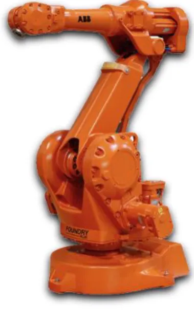
[image:16.595.338.528.352.666.2]In dealing with a 6 axis robot arm, a detailed knowledge of the programming language used for its operation is required. An understanding of its capabilities and its limitations is also imperative. Ideally using voice recognition technology as a method of control would require a fast response to input from the user. Considering the processing power of the average
computer and the time needed to execute an algorithm, response to input for this particular project can be expected to be relatively slow.
Creating a reliable system with the resources available can be quite difficult and time consuming. Thus it is important to state that providing an input and obtaining a response from Garfield is the basic objective needed to be reached. From here, increasing the efficiency, response time and manoeuvrability of Garfield becomes the next focus in this project.
1.2 Project Aim
The primary aim of this project is to design, develop and implement a voice recognition and control system onto Garfield, the 6 axis robot arm. This prototypical software-based system will look at demonstrating the concepts of voice recognition and control and explore its limitations. The project will involve the creation of a voice recognition algorithm in Matlab and a program in RobotStudio which will integrate together over a TCP/IP socket connection. The system must provide an accurate means of control, allowing the user to display the capabilities of 6 axis robot arm control. With regards to speed, it is important that the arm responds quickly in real time to ensure the safety of the user. The system must first demonstrate a basic response to voice input and be simulated on RobotStudio software before being implemented onto the 6 axis robot arm itself.
This project aims to investigate methods of voice recognition, analyse the best method for this application and implement it using various sound processing techniques and algorithms. This prototypical software will be tested, analysed, evaluated and further developed to improve such performance criteria as speed, accuracy and manoeuvrability.
1.3 Project Objectives
The project aim was reviewed and split into a number of objectives for completion.
Identification of current voice recognition techniques
Identification and Investigation of best suited voice analysis method
Development of algorithm in Matlab addressing this method
Development of code using RobotStudio software to integrate with this method
Combine and Implement these two developments in simulation package
Evaluation of prototypical software
Investigate any modifications to improve system performance
Implement these modifications and Evaluate
Implement the prototypical software onto Garfield
1.4 Overview of Dissertation
The dissertation is organised as follows:
Chapter 2 Investigates the relevant research papers on the voice recognition subject area and explores the techniques used to apply this form of control. These techniques will involve signal processing, model building, program communication and simulation elements. There relevance to this particular application will be discussed and evaluated.
Chapter 3 States the methodologies to be undertaken in order for project completion. It outlines the strategies used in creating the system software and its implementation onto Garfield. This chapter also looks at the relevant risks involved in this project and a formal assessment and evaluation of these. Resources needed for the project are also identified and discussed.
Chapter 4 Details the design of the Voice Recognition and Control system as per the relevant theory explored in Chapter 2. The methods used in this process are explored and creation of the system followed all the way to the implementation stage. This involves investigating the processing algorithms, communication link, simulator code and command theory.
Chapter 5 looks at simulation performance involving Error Rates, rejection and system response times. Evaluation of the system is also conducted to seek out and identify problems such as delay and misinterpretation. Future improvements for the system are also somewhat explored.
Chapter 2
Literature Review
2.1 Chapter Overview
Over the years many people have dedicated time and money into researching the properties of speech which gives every person a sense of individuality. An understanding of how to manipulate these properties and effectively use them to transform the way we produce sound has been sought with high priority. With such an understanding, it has paved the way for voice to be used as a means of control and security. This technology has the potential, with the right technology, to replace a number of existing control methods to make our lives easier and quite possibly safer.
This chapter examines the basic concepts of speech, in particular its spectral properties and how they are obtained. It also looks at the way in which these properties can be manipulated in order to distinguish between a number of different utterances or words. Relevant literature will be explored to extract the techniques involved in speech analysis and detail their physical operation.
2.2 The concept of Speech
The human voice is a very unique concept and varies greatly from person to person. Even though everybody is different in this way, it just so happens that the same technique is applied by everyone in order to produce sound. From the moment you first breathe air into your lungs muscles in your throat are preparing for whichever word you are planning on saying or in some instances, planning on not saying. No matter how you approach the projection of speech there are always 3 distinct ways in which speech can be excited (Plannerer 2005):
Voiced excitation
Unvoiced or Voiceless excitation
Transient excitation
Voiced Excitation
When exhaling, air streams through the larynx, passing through the glottis (essentially the vocal chords and the space between them). During voiced excitation the glottis remains closed until enough pressure is present to cause it to open. In doing so, this creates a quasi-periodic vibration which can differ in both period and magnitude. This essentially creates the frequency at which the sound is released.
Unvoiced (or Voiceless) Excitation
Transient Excitation
This excitation happens when the muscles in the pharynx (oral cavity) are expanded and contracted to produce changes in air pressure. When opening the mouth, this air pressure gives a certain burst that gives definition to particular syllables in words.
In knowing these simple characteristics of speech we can now look at it from an analysis perspective. An utterance will be created using a range of these 3 excitations, with each excitation having important variables.
Firstly we can look for a fundamental frequency as generated by voiced excitation.
Secondly we can look for peaks in the spectral distribution of energy and zero crossings.
Thirdly we can look for short silences produced over time caused by the build up of pressure during transient excitation (Kumar & Rao 2011).
From here we now know what to look for when conducting an analysis and with the right tools create a model that correctly identifies an utterance. The variables we have mentioned above can be found and manipulated using different techniques in signal processing.
2.3 Speech Processing
2.3.1 Sampling
In order to obtain the information detailed in section 2.2, a short time signal must be recorded into a processing engine such as Matlab. This is generally done using a microphone and the user’s voice, or the sound can be generated by a program or instrument. During recording, the short time signal (sound) undergoes an analogue to digital conversion at a pre-defined sampling frequency. For the case of the human voice, 8 or 16 kHz is an appropriate sampling frequency depending on the desired accuracy and quality. This data can then be saved as a physical recording in the desired format (.wav).
2.3.2 Pre-emphasis
Once the signal has been sampled and data is saved, it requires a certain amount of filtering in order for further processing to continue. The now ‘digitised signal’ is run through a emphasis stage where the higher frequencies are magnified within the data set. This pre-emphasis, essentially eliminates the -6 dB per octave decay of spectral energy (Plannerer 2005).
The pre-emphasis filter can be defined in the following equation.
Y [n] = X [n] – 0.95 X [n-1] ...equation (2.1)
Where
X[n] is the digitised signal
Y[n] is the magnified output signal.
0.95 represents the percentage of the original signal assumed to be present in the following sample.
2.3.3 Framing
Once a time signal has been pre-emphasised, the need arises for it to be framed. Framing, divides the data into a series of overlapping segments that range from 20 to 40 ms in length. The importance of framing is based on the fact that, smaller time segments produce a more accurate stationary representation of the time signal ensuring the spectral estimate obtained later on is reliable. If the segments are to small there are not enough samples to give a reliable estimate and if the segments are too big the signal changes too much in order to obtain an accurate estimate (Lyons 2009).
The segmentation will allow the signal to be processed over smaller time frames of N samples. Adjacent frames become separated by M, which is less than N. Typical values for N are = 128, 256 or even 512 and that for M are of the order of M<N (i.e. 50, 100, 200).
2.3.4 Hamming Window
Now considering that the time signal has been segmented into a number of overlapping frames it becomes quite important that a hamming window is applied to each frame. The hamming window allows for the smooth transition between frames by reducing the side lobe that causes unwanted radiation in the frequency domain. This improves the time signal quality and removes unwanted frequencies caused by the framing process.
Using the output frequency from before Y [n], it is multiplied by a windowing equation W[n] in order to obtain the result Y1 [n].
This is shown in the following equation:
W [n] = 0.54 – 0.46 cos (2πn/N-1) ...equation (2.2)
For:
0 ≤ n ≤ N-1
where:
Therefore Y1 [n] = Y [n] x W[n] ...equation (2.3)
2.3.5 Discrete Fourier Transform
The next step in the process involves addressing each frame of N samples created above and converting them from the time domain to the frequency domain. This will enable the distinction of the key frequencies present in the sound as explained in section 2.2.
Currently the frames are in a form that is understood to be a function of time. Performing a Discrete Fourier Transform on each of these frames changes it to a function of frequency. This is also referred to as changing it to the frequency domain, where the frequency distribution and magnitude of this distribution in a sound is displayed. This form shows the most dominant frequencies present in the sound, which is an important factor is determining the major differences between two utterances.
The Discrete Fourier Transform can be applied as follows (Kumar & Rao 2011):
...equation (2.4)
for:
where:
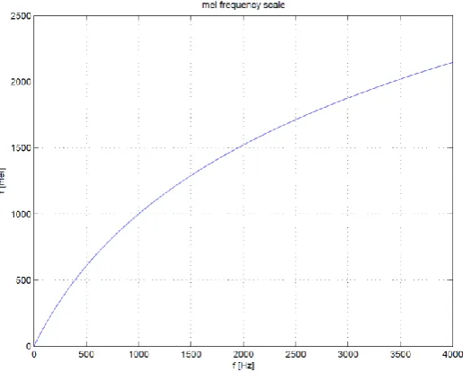
2.3.6 Mel Frequency Scale and FilterBank
[image:26.595.184.442.269.476.2]Knowing that the human ear does not follow a linear frequency resolution and instead builds several clusters of frequencies and sums the spectral energies within these clusters, the non-linear warping of the axis values can be modelled using the correct method. This method involves using the so-called Mel Scale. This particular scale aligns with those properties that need to be extracted from speech signals making it an effective analysis tool. The Mel Scale can be seen in the following diagram.
Figure 2 - Mel Frequency Scale
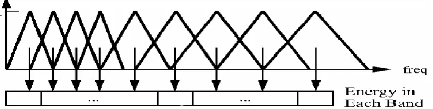
In order to find the right spectral properties within the speech signal a number of triangular filters are applied that calculate the sum of the function’s spectral components. The equation below defines the Mel Frequency Scale as seen above; the filters are spaced according to this equation.
Figure 3 - Triangular Spaced Filters
Applying this filter bank will give a number of spectral values depending on the amount of triangular filters used. The standard number of filters in voice processing is set at 26. Each of these filter values will represent the sum of the spectral components found inside the filter (Lyons 2009).
2.3.7 Mel Frequency Coefficients
Now having Mel values from each filter output, the log of the filter bank energies can be obtained and can be converted back to the time domain using the Discrete Cosine Transform. This, in turn produces the so-called Mel Cepstrum Coefficients, which represent the acoustic vectors for this particular pattern of speech. Every utterance analysed in this process now is outputted into a sequence of acoustic vectors for further interpretation (Lyons 2009).
Following this common procedure there are a number of principles that can be applied to essentially perform the task of voice recognition. These are:
Hidden Markov Model
Dynamic Time Warping
Artificial Neural Network
2.3.8 Hidden Markov Model (HMM)
The Hidden Markov Model has become the most popular way in which general purpose voice recognition is performed today. This popularity is due to its simplicity and computational feasibility in comparison to other methods. Essentially this statistical form of modelling outputs a sequence of symbols or quantities based on a stationary input signal. Considering that each window of speech being analysed is over such a short period of time, it can be seen as a stationary signal and applied using the HMM.
Given a range of stationary inputs, HMM uses a combination of comparison and prediction to match the input with a pre-recorded input model. It will determine likelihood based on the statistical distribution from each observed vector input from the Discrete Cosine Transform. The most likely model representation will then be found and can be used to display the utterance that was used as the input. In general the models used by this process are easy to train, pushing the capabilities of a HMM to deal with vocabularies of 5000+ words. Although, the theory shown above is of a basic nature and more refined techniques would be needed to increase vocabulary size, speaker adaption and noise resistance (Iqbal, Mahboob & Khiyal 2011). Re-creating this technique for a system described by this project would allow for great recognition results and larger vocabulary sizes, but the coding involved in this process may absorb too much time.
2.3.9 Dynamic Time Warping (DTW)
distinguishing between two different people but may be less effective when distinguishing between utterances, especially if they are of similar patterns.
2.3.10 Artificial Neural Network (ANN)
This particular method used in voice recognition has been quite successful in isolated word detection, speaker adaption and phoneme classification. It uses a method similar to that of the Hidden Markov Model, but does not make any assumptions on the statistical properties of the input features. Instead of basing its prediction on probability and the pre-recorded input model, ANN’s set out to ‘learn’ from the observed data and make a judgement based on what they know. This process does work well for isolated word detection but runs into problems when performing continuous word detection, limiting its power of computation. This would make it a good choice for the recognition stage of the project considering one word commands are to be used, although coding this particular type of network could be quite a hassle.
2.3.11 Vector Quantisation (VQ)
There are a lot more techniques and tricks in the industry today that allow voice to be used as a tool for control. These are used in very complicated algorithms that have been developed over a number of years, with results that far surpass those obtained using these basic principles. In order to explore the concepts of this technology these basic methods needed to be used in order to obtain an understanding and some basic results.
2.4 Speech as a form of control
Understanding the properties of speech and the way in which it can be manipulated becomes a very important step in conducting this project. Following this, is an understanding of how voice can be used in order to control a robotic device. Knowing what has been said in the sections above, some knowledge of voice and sound properties can be applied in order to define parameters for control.
It is well known that people have a voice that is unique to them and them only. It is quite common however for people to have a voice with the same pitch as another. Even though they may have the same pitch, they will have different spectral properties which affect both loudness and clarity. It is important to understand that when deciding to use properties of voice for a means of control, using consistent utterances of commands is vital, especially when basic methods of voice recognition are being implemented. It also makes it difficult to achieve successful results in the presence of noise.
Creating a list of commands for the purpose of control is a major part of the design aspect. Not only must these words be straight forward and clear, but they must avoid any similarities between them. Having similar sounding and pronounced words can affect the success rate of the algorithm and confuse one action with another; this is mainly due to the simplicity of the algorithm.
In order for voice to be used to control more than 1 variable, a number of considerations must be taken into account:
As mentioned previously, the commands used and what they stand for
The complexity of the algorithm, i.e. isolated word or multiple word recognition
Pitch or frequency can be difficult to manipulate by the average person
Background noise
With these considerations in mind, the extent to which the voice can be used is limited and the flexibility of the system is impacted. In order to combat these limitations a number of solutions could be implemented. These include:
Using more advanced algorithms – which would allow larger vocabularies, the use of multiple word commands and multiple speaker recognition
Adding a simple tone or frequency generator to control an extra variable
Adding numbers prior to or after the commands
The success of the voice recognition system will depend on which technique is chosen by the operator and how it performs in real time.
2.5 The 6 axis Robot arm
Robotic arms are a very popular choice for industrial work around the world in this present day. They are called upon to do a wide range of tasks whether it is, to simply lift, cut, weld or shape various materials and objects. Without them, the manufacturing industry would not only be less efficient and less productive compared to now but less successful and more expensive. It is clear that robotics will play an important part in the future of the human race and will require more complicated forms of control as a result.
2.5.1 History
From this point on a number of developments have been made with regards to the robot arm, these include:
1959 – ‘Unimate’ – first ever robot arm created which was controlled by a program on a magnetic drum.
1961 – First robot arm installed at GM factory to assists in the manufacture and movement of car parts.
1969 – First automated spot-welding robot was installed at GM factory.
1970- First world conference on Robotics which gave researchers and engineers an opportunity to present their work and share ideas.
1973 – 3000 industrial robots in operation.
1974 – First microprocessor controlled industrial robot created in Sweden and First mini computer controlled robot arm marketed in Cincinnati.
1975 – First Cartesian-Coordinate robot used in assembly applications.
1978 – First 6 axis arm with its own control system.
1981 – Direct drive introduced for movement and later on electro-drive motors for greater control.
1992 – First robot packaging application (6 robots packing pretzels) sold.
1999 – Laser beam guiding introduced with robot arm
2003 – 800 000 industrial robots in action around the world.
2004 – Remote pendant used for control of arm.
2006 – changes to material properties allowed reduction in weight and more responsive
Present Day – memory systems are becoming physically smaller but increasing in size (with regards to memory) and becoming faster (Robotics 2012).
2.5.2 RobotStudio
Ever since the birth of the robot arm, methods for its control have been ever developing as technology has been expanding. From simple programs to artificially intelligent algorithms, the industrial robotics industry has come a long way in its short lifetime. Today, ABB robotic arms use a software tool called RobotStudio, which implements a simple programming language to initiate a range of functions, controlling all aspects of all 6 axes. It allows the user to move the end of the arm to any point in the 3-Dimensional space it is mechanically limited to. This movement is based around the Cartesian coordinate system where a 3D vector is used to move the arm to different points in the space. In this particular case the arm has two 3D vectors that it requires input for, these being:
The Base coordinate (x, y , z)
The Tool coordinate (x, y , z)
The base coordinate moves the main body of the arm with reference to axis 1 (or the base) and the tool coordinates move the tool tip with reference to the centre of axis 6. The use of these two coordinate systems allows the arm to operate within an accuracy of approximately 0.01 mm. The speed at which this machine can operate depends on the users input settings but is also based on the programs effective use of zones and angles when moving between designated points. This variable speed is measured in millimetres per second (mm/s). As mentioned in the previous sentence, it also has the capability of smoothing out its travel path with its clever use of zones which is also user defined. These zones allow the arm to pass near a point in the path (or set of data points) instead of travelling straight through it, to prevent any ‘square cornering’ and smoothen out its desired path. This not only increases the efficiency of the robot arm but reduces wear on the axis joints (Robotics 2013).
the joint movement system would be perfect for maintenance inspections and defect checking, as each axis could be individually moved with ease without having to worry about ‘which point in space would best show me the limits of axis 4’.
2.5.3 RobotStudio Coding (RAPID)
The RobotStudio platform is run by a language called RAPID which has many similarities to those techniques found in C, C++, Java and Matlab. In general, the language is quite simple and has been created to ensure easy access to the many functions of the 6 axis robot system. The RAPID language has a modular based approach, where many different routines can be created and called upon when needed, making it quite simple to add in routines whenever or however many times they are needed (Robotics 2013).
Each foundation program is held within a Module and is annotated as follows:
MODULE Socket //Start of module ‘Module name’
ENDMODULE //End of module declaration
Figure 4 - Module annotation
Following the declaration of the start of a Module, all data values contained with the module must be declared. These values can be:
Variable (VAR) – can be changed through program execution
Constant (CONST) – cannot be changed once program is executed
Persistent (PERS) – will retain value if it is changed during program execution and the program is restarted
Within each Module that is created a number of Procedures can be called which deal with:
various movements
error checking
configuration settings
An example of this basic layout can be seen below:
MODULE Socket //Start of module ‘Module name’ VAR num speed:= 100; //Variable declaration (datatype = number) CONST string one:= “one”; //Constant declaration (datatype = string) PROC main() //Start of procedure ‘Procedure name’
ENDPROC //End of procedure
ENDMODULE //End of module declaration
Figure 5 – RAPID program Layout
It is important to note that all declared procedures can be called from PROC main() and do not have to be created in order of operation. There order will depend on how they are listed within the main procedure and be executed chronologically (Robotics 2013).
Creating programs or procedures within RobotStudio can be done in 2 distinct ways.
Offline mode
In this mode the procedures are listed within an editor for user read and write access. Multiple functions are also available to the user to help create the procedures (e.g. Path creation). Simulations can be run through this mode and visualised on screen.
Flex Pendent
This mode gives complete control to the remote flex pendant where editing of the procedures can also occur. A number of quick setting functions are also available to reduce programming time and increase efficiency. Control of the robot can also be given to the Flex Pendent and the procedures run remotely from this handheld device.
2.5.4 Previous Industrial Application
Implementing a technique such as voice control on this sort of system has been done before as seen in (Pires 2005). Here an ABB 6 axis robotic arm similar to that of Garfield was programmed and controlled to perform welding functions in the lab.
The robot arm was controlled using Automatic Speech Recognition (ASR) software. Microsoft’s speech engine, Microsoft Speech Application Programming Interface (SAPI), Microsoft’s Speech SDK (v5.1) and .NET 2003 framework were the packages used for the software platform.
This particular project used simple commands to firstly recognise the robots name (in case other robots were included), then it identified the user and finally it performed the commanded tasks.
The user called upon routines to follow as opposed to directing the arm about (mainly due to the precision involved in the welding process).
This particular paper showed great success with this software implementation on the industrial robot and showed the potential of voice recognition programs within the industry (Pires 2005).
2.6 Communication Link (TCP/IP)
In order for any machine to communicate with another, a link is always established in real time for the handling of instructions and data. An essential part of this Voice recognition and control system is the ability for the two programs in question to communicate with each other seamlessly. In order to do so, a connection using TCP/IP protocol seems to be the right idea. This protocol is supported by both Matlab and RobotStudio and allows interaction between the two programs in a client/server relationship.
Socket messaging can be implemented using the following code:
Server Socket t = tcpip('0.0.0.0', 30000, 'NetworkRole', 'server');
fopen(t);
Opens Socket connection and waits for client connection. data = fread(t, t.BytesAvailable, 'double');
Reads data once connection is made.
Client socket data = ? (command data) Define ‘data’ ready for sending.
t=tcpip('localhost', 30000, 'NetworkRole', 'client');
fopen(t)
Create client interface and open it. fwrite(t, data, 'double');
Write ‘data’ to the socket.
Once this is done the socket can be closed and the link broken once the program has finished sending data and/or commands.
IP Address Port Enables support for server sockets
2.7 Chapter Summary
This section has identified the literature outlining relevant methods involved in creating a Voice Recognition system for a 6 axis Robot Arm. It has explored the concepts of speech signal processing, application to application communication and the use of RobotStudio. The search for a greater form of control has been proven to be on-going and requires the investigation into more futuristic methods. The use of the voice as a tool for control is quite viable and developing a system which can demonstrate its functionality is of high priority.
Chapter 3
Methodology
3.1 Chapter Overview
3.2 Research and Development Methodology
The research and development methodology presented here was developed with the project objectives in mind. These objectives have been broken down into a series of major tasks to highlight what needs to be achieved.
Implementing a Voice Recognition and Control system on the 6 axis robot arm, Garfield has called for the design and production of a system that is simple to use, reliable and works in real time. This system needs to able to distinguish the relevant voice commands from sample inputs in order to produce movement on the robotic arm.
For the basic development of this system, there is the need to research and obtain, both hardware and software components. These two components will form the basis of the system
and allow its completion.
At a hardware level, the system requires a microphone in order to record voice models and receive commands. It is to be connected to a suitable computer that has both a compatible sound card and the software programs in which it is to interface with. This computer will most likely be one that has access to the Robot arm simulation software and eventually change to the computer in charge of operating Garfield.
On a software level, the system requires a platform that:
Waits for and receives a range of inputs
Manipulates these inputs into a form that can be compared and identified
Produce an output that reflects the true nature of each input (in real time)
Communicate this output over a TCP/IP socket between 2 separate pieces of software
Recognise these outputs and use them as viable inputs in order to create movement with the arm.
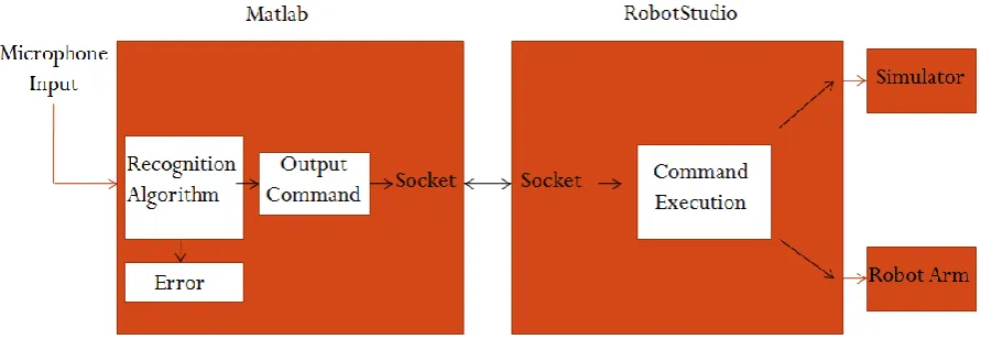
A simple block diagram of the interaction between the hardware and software levels is shown below.
Figure 6 - System Block Diagram
In order to evaluate the performance of this system, the design of suitable testing methodologies and analysis strategies have to be considered. The tests involved with such a system should present information that reflects recognition accuracies and rejection rates, as well as information on response times for real time operation. Parameters used during testing will be kept constant and those uncontrollable variables dealt with to ensure the integrity of the results. Evaluation of the system based on the results achieved will be included and be used to form recommendations for further work and future development.
3.3 Task Analysis
All in all the development of this project can be refined to the following processes: 1. Identification of required hardware and software for this application. 2. Research and development of Voice recognition techniques.
3. Design and Implementation of Voice Recognition Algorithm. 4. Design and Implementation of Robot arm code.
5. Design of communication link between programs (integrate the system into one). 6. Train, Test and evaluate the system in simulation
Ensuring these 7 steps are achieved and appropriate results are obtained, the project can be deemed successful. They will act as milestones in the development of the system and in turn, indicators of project progress. The following is an analysis of the details of each of the tasks above and identifies the resources required for each.
3.3.1 Hardware and Software identification
A number of items must be identified and obtained before different parts of the system begin development.
In saying this, the voice recognition system will require the following resources:
Microphone – model yet to be determined (preferably of high quality)
Computer – Lab computers with access to required simulation software. The computer must be appropriate with regards to processing speed and sound card quality.
Matlab – most recent version or closest to, with complete toolbox
RobotStudio – software required to run ABB 6 axis robot arms
TCP/IP socket protocols – for communication between programs
These resources will be used throughout the following processes in order to achieve completion.
3.3.2 Voice Recognition Algorithm
From here it will be required to interface with the simulation software required in testing for the 6 axis robot arm. Incoming inputs will need to be recognised and matched with specific outputs to communicate across this interface.
This algorithm will use functions associated with the Voicebox Toolbox (Brookes 1998) to create a form of voice recognition.
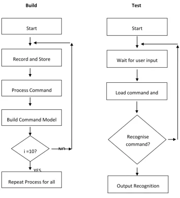
[image:43.595.134.506.250.660.2]A simple block diagram of the two features of the algorithm is shown below in figure below.
Figure 7 - Simple Process Diagram
Building the command models is done using the simple process simulated by the block diagram on the left in figure 7. 10 utterances must be recorded for each command to achieve
Output Recognition Results Wait for user input
command Start
Load command and process
Recognise command?
NO
YES
Test Build
Start
Record and Store command
Process Command
Repeat Process for all commands
i =10? NO
fair results. Testing an utterance against these command models is shown by the block diagram on the right.
This will require the following resources:
Microphone
Computer with pre-installed Matlab software and coding
3.3.3 Robotic arm Coding
This process will involve preparing a program based on the ABB programming language used by RobotStudio. The routines created in this process will perform command specific actions that are called for by the inputs from the Matlab algorithm. The actions could be any of the following:
Axis 1 – Left or Right
Axis 2 – Up or Down
Axis 3 – Up or Down
Axis 4 – Clockwise or Anticlockwise
Increase or Decrease Speed
End procedure
Perform Demonstration
The coding will be based on the following principle:
Each command will move the robot a specific distance in whichever direction the command defines. It will not just call a program with pre-defined points in the 3D
space to execute, unless demonstration of this idea is needed.
The resources required for this include:
Computer with pre-installed RobotStudio Software
Input source to test coding
Manual or Library of commands and routines
Network license for Software
3.3.4 Communication Link
This step in the project is quite important for the complete integration of the system. Without a link between the two programs for the voice recognition and RobotStudio code, the system will not function. This particular link will use a tool common to both applications that can be applied to send and receive messages. TCP/IP socket messaging is the ideal method of communication between these programs as it uses Ethernet connection protocol to relay messages between the client and server. It is essential that this link is developed quickly to allow more focus on the other parts of the project.
3.3.5 Testing and Evaluation
To validate the performance of the voice recognition system, testing must be conducted under a number of conditions. These conditions include:
no background noise – generally total silence with only the user speaking
Background noise – the user speaking with industrial background noise
Background noise – random noise/commands
Testing the response time of the system is another important part of the project, as it will give the user an idea of how well the system would suit specific jobs that may require its use. These response times will be calculated over a range of movement increments and compared. From the results of this stage, a qualitative analysis can be conducted and future improvements can be recognised and applied to the system for more testing. This will increase the reliability of these methods and create a better platform for further expansion. The resources required for this task are:
All system components
User voice input
3.4 Consequential Effects
3.4.1 Sustainability
The Institute of Engineers Australia (Engineers 1997) provides a set of guidelines that addresses the aspects of sustainability within Australia. This particular institution forms the largest collective group of professional engineers within Australia with world renowned accreditation available for its members. The guidelines they have laid out form the basis of evaluation processes that relate to the environmental, socioeconomic and cultural sustainability of a project, over its lifetime.
With regards to environmental safeguards within the project dimensions, avoiding excessive emissions created by the equipment could be of benefit, as well as utilising power saving techniques when operating in the laboratory.
This sort of technology is one that could slowly develop into that seen in current day science fiction movies where robots are fully autonomous and have a mind of their own. Generally these types of robots are portrayed as out of control and dangerous but on the other hand these artificial humanoids could be a great use in everyday life. Performing those tasks which are boring, repetitive and even dangerous. Society by this time, would be completely different than what it is today and there is no way of knowing exactly how it could have impacted. The most likely people impacted by this technology would firstly be those involved with industrial robotics and then quite possibly it could evolve and impact those everyday people. In this case, before the technology is even implemented around the world a consensus should be reached by the people to decide whether or not they feel it is appropriate for such autonomy to be present. Will it be ethical for us to create and almost living machine?
Project costing for this project is quite low considering the hardware and software required for all aspects of the project have been made readily available by the university.
The impact of this technology on the labour force could be quite substantial. Due to the improved interaction between machines and human beings more jobs will be semi automated taking away the number of people required to do specific processes. On the lower level, low income earners will be affected dramatically but on the higher level, big business will prosper with increased productivity and efficiency.
Overall this project has the potential to influence a large proportion of people and provide a better understanding of robotics and automation in the process.
3.4.2 Safety
crashes and put the user at risk. Measures have been taken to ensure the safety of users in case of such an occurrence. Shielding surrounds the 6 axis arm in case this sort of error reaches the real life implementation stage, otherwise bugs and errors are generally picked up during simulation.
The equipment used in the project was required to conform to relevant Australian and international safety standards. Where it was necessary, precautions were taken to minimise the risk of the operator and any others in the vicinity.
3.4.3 Ethical Considerations
These considerations are based on the code of ethics provided by Engineers Australia which lists guidelines for engineering practices. The guidelines cover such qualities as integrity, leadership, competence and sustainability. It is essential that this code of ethics be followed closely at all times during the project. This will ensure that the outcomes reached and ideas presented are done with the best interests of the community and environment in mind.
3.5 Risk Assessment
3.6 Research Timeline
The tasks laid out in the Gantt chart found in Appendix B, show the expected start and finish times of particular sections of the project and reflect those pointed out in the methodology.
3.7 Chapter Summary
Research and Development methodologies have been explored throughout this chapter, ready for further expansion in later sections. The project was organised into a number objectives that must be completed in order to achieve success, along with the resources required for each of these. The objectives were also scheduled within a timeline to set dates of achievement.
Chapter 4
Design & Implementation
4.1 Chapter Overview
The following chapter contains detail on the design and implementation of the Voice recognition and Control system, based on the methodologies and theoretical content defined in the literature in Chapter 2 and requirements highlighted in Chapter 3. This chapter will outline the processing methodology used by the recognition system, the interfacing method used for communication with the robot software and its implementation as a complete system.
4.2 Voice Recognition Methodology
The voice recognition and control system used in this project requires a certain level of understanding, about the processing techniques involved with each of the utterances used. In order to expand this understanding, the need arises to explore the processing techniques used on the data and how it is manipulated to create a voice based recognition system. The details of this voice based systems implementation will be discussed in later sections.
The signal processing techniques used for this project (as seen in section 2.3) can be divided into the following stages:
Pre-emphasis
Silence Detection and Data reduction
Framing and Windowing
Periodogram-based power spectral estimate
Mel Filter Bank
Log filter bank energies and Discrete Cosine transform (Finalised MFCC)
Model Building
Recognition using Euclidean Distance
It is important to understand that the following processes aim to extract those features in the voice that are essential in identifying the linguistic content of the speech and also discarding those features that represent things such as background noise and emotion.
These stages will now be investigated in detail.
4.2.1 Pre-Emphasis
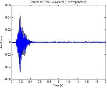
In order for the processing techniques to begin, 10 voice samples of each command were recorded at a sampling frequency of 16 kHz and stored in ‘command’ arrays. These voice samples were selected to last for the duration of 2 seconds, considering that the average
The above figure shows the utterance of the command ‘ONE’ before pre-emphasis. In its current form little can be done in terms of recognition, therefore it requires further processing and normalisation to obtain the data relevant to the problem.
To prepare it for further processing and obtain the best results from each signal, each utterance is run through a pre-emphasis filter with the following characteristics:
Y [n] = X [n] – 0.95 X [n-1] ...equation 2.3
Where Y[n] = output signal X[n] = input signal
The value of 0.95 is the standard value for a pre-emphasis filter and can be changed if higher frequencies need to be emphasised more or less.
[image:52.595.128.499.430.734.2]The result from the filtering process can be seen in the figure below.
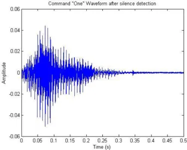
4.2.2 Silence Detection and Data Reduction
Following the process of Pre-emphasis, the speech signal can now be shortened to obtain the most important samples for the recognition process. This means reducing the total number of samples in each utterance by removing the ‘silence’ before each utterance. In order to do so, a small detection technique is applied to the front end of the signal.
This detection technique involves:
Setting up a threshold to determine the difference between the ‘utterance’ and ‘background’ or ‘ambient’ noise.
Searching the front end of the data sample for breaches of this threshold.
Determining whether the breach is actually the ‘utterance’ or some form of random noise.
The threshold limit selected for the project was an |amplitude| of *0.04* units. This threshold was determined to be a reasonable borderline between ambient noise and the utterance itself. The following excerpt of code from Appendix D shows the detection process.
% Silence Detection
% Wait for clear start of signal
while abs(Preemphtest(i))< 0.004 || abs(Preemphtest(i+20))< 0.004 || abs(Preemphtest(i+40))< 0.004 || abs(Preemphtest(i+60))< 0.004 || abs(Preemphtest(i+80))< 0.004 || abs(Preemphtest(i+100))< 0.004
i = i+1;
end
It can be seen that whilst the conditions remain under the threshold the ‘i’ counter will continue to increment. Once all of the conditions are breached in the same iteration, it is clear that some form of utterance is present in the data and the increment is stopped.
From here the code will take the incremented value (where the utterance starts) and extract the succeeding 8000 samples from each utterance data set.
% Signal will start from the calculated position atest = Preemphtest(i:length(Preemphtest));
% Reduce samples from 32000 to 8000 for remainder of processing (as command
% will be present within the 8000 samples) atest(8001:length(atest))= [];
Preemphtest = atest;
This reduces the amount of samples from 32000 back to 8000, which will decrease the calculation time and improve the response time. The result of this process can be seen in the following figure.
Figure 12 - Command 'ONE' after silence detection
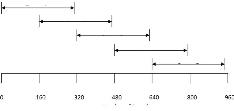
4.2.3 Framing and Windowing
The next step in the process is to break up each dataset of 8000 samples into a number of M frames of size N, with a step size between these frames of Δ = N/2. The following parameters could then be chosen:
Segment Length = N = 320 samples
Step size = Δ = 160 samples
Number of frames = M = 49
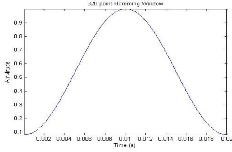
These parameters produce frames that are 20 ms long which is believed to be the optimum length for obtaining a good spectral estimate from the frame. If the frames are any longer, the signal changes too much within the frame to get an accurate stationary estimate of the time signal. If they are any shorter, there are not enough samples in the frame to obtain a reliable estimate of the time signal properties.
[image:56.595.114.514.413.604.2]The framing process can be seen in the following diagram.
Figure 13 - Framing Diagram
Once each frame has been assigned to values from the dataset, a window must be applied to each frame. In this case the ‘hamming’ window has been selected as it is the standard window type for any Mel Cepstral Feature extraction. The fundamental equation for this window can be found in section 2.3.
Number of Samples
0 160 320 480 640 800 960
Frame 1
Frame 2
Frame 3
Frame 4
A 320 point hamming window can be seen in the following diagram.
Figure 14 - Hamming Window
Applying this window to each of the frames is done before the Fast Fourier Transform to smooth out the response on the edges of the frames. It essentially minimises the side lobe and prevents any unwanted radiation in the frequency domain, improving the quality of the sound and accuracy of the feature extraction (Plannerer 2005). The result of multiplying the hamming window with the first frame is shown below.
[image:57.595.135.503.484.737.2]4.2.4 Discrete Fourier Transform
At this point in the processing stage the data is ready to undergo a change to the frequency domain through the Discrete Fourier Transform (DFT) as defined earlier in section 2.3.
for
Where:
‘i’ denotes the current frame
‘N’ denotes the sample size
‘K’ denotes the length of the DFT analysis
s(n) is the time domain signal
h(n) is the hamming window
is the complex DFT
This change of domain allows the spectral components of the utterance to be accessed and manipulated for the recognition process. The DFT can be performed in Matlab using a Fast Fourier Transform algorithm that reduces calculation time.
4.2.5 Periodogram based Power Spectral Density (PSD) estimate
The PSD estimate is a calculation based on those formulae defined earlier in section 2.3. This process, along with the DFT, acts to mimic the operation of the cochlea (the organ in the human ear). It extracts those frequencies that human’s base their perception of speech upon, which becomes very useful when dealing with automatic speech recognition (ASR).
The 257 coefficients obtained from the DFT in 4.2.4 are applied to these calculations to obtain a Power Spectral Density Estimate for the current frame. This is done by taking the absolute value of the complex Fourier transform, squaring it and multiplying it by 1/frame length.
From the above equation a set of 257 coefficients representing the PSD estimate are calculated.
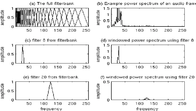
4.2.6 Mel Filter Bank
[image:59.595.134.515.531.747.2]The Mel filter bank is a bank of linearly spaced, overlapping, triangular filters that stretch across the frequency spectrum. The Mel scale to which these filters are spaced aligns with that of the human ear. This makes the algorithm more sensitive to pitch changes at lower frequencies and essentially simulates the operation of the human ear. The diagram in the figure below shows the simple concept of the Mel filters and their application to the PSD estimate (Lyons 2009).
In order to create a filter bank based on the data obtained previously, another function, melbankm.m was used. This function was also taken from the VOICEBOX : Speech Processing Toolbox (Brookes 1998) to obtain a filter bank of 26 filters (26 is the standard number). Multiplying this with the result from the rfft.m function would now obtain a set of 26 coefficients demonstrating the sum of the components within each of the 26 triangular filters.
4.2.7 Log filter bank energies and Discrete Cosine Transform
In keeping with the spectrum of the human ear the log of the filter bank energies must be taken. This due to the fact that loudness is not heard on a linear scale and the respective energy levels may give false information when comparing on a linear scale.
Since the application of the filter bank, correlation between the data has increased due to the overlapping triangular filters. In order to decorrelate the data and reduce the effects of correlation the Discrete Cosine Transform is applied to the frame, in turn achieving an accurate representation of the feature vectors that needed to be calculated. These, in essence, are the Mel Frequency Cepstral Coefficients (MFCC) (Lyons 2009).
For the purpose of this speech recognition algorithm the first 13 coefficients of this result relating to spectral power were kept for the recognition process and the rest discarded. This meant that 13 coefficients per frame were kept and collectively stored in their respective command matrices.
4.2.8 Model Building
The creation of the command ‘Models’ is an impo