UNIVERSITI TEKNIKAL MALAYSIA MELAKA
DEVELOPMENT OF SMALL PORTABLE AIR CONDITIONER
BY PELTIER MODULE
This report is submitted in accordance with the requirement of the Universiti Teknikal Malaysia Melaka (UTeM) for the Bachelor’s Degree in Mechanical Engineering Technology (Refrigeration and Air Conditioning System) (Hons).
by
MUHAMMAD SYAHRIL BIN ABD AZIZ B071410571
951227045275
UNIVERSITI TEKNIKAL MALAYSIA MELAKA
BORANG PENGESAHAN STATUS LAPORAN PROJEK SARJANA MUDA
DEVELOPMENT OF SMALL PORTABLE AIR CONDITIONER BY PELTIER MODULE
SESI PENGAJIAN: 2017/18 Semester 1
Saya MUHAMMAD SYAHRIL BIN ABD AZIZ
mengaku membenarkan Laporan PSM ini disimpan di Perpustakaan Universiti Teknikal Malaysia Melaka (UTeM) dengan syarat-syarat kegunaan seperti berikut:
1. Laporan PSM adalah hak milik Universiti Teknikal Malaysia Melaka dan penulis. 2. Perpustakaan Universiti Teknikal Malaysia Melaka dibenarkan membuat salinan
untuk tujuan pengajian sahaja dengan izin penulis.
3. Perpustakaan dibenarkan membuat salinan laporan PSM ini sebagai bahan pertukaran antara institusi pengajian tinggi.
4. **Sila tandakan ( )
SULIT
TERHAD
TIDAK TERHAD
(Mengandungi maklumat yang berdarjah keselamatan atau kepentingan Malaysia sebagaimana yang termaktub dalam AKTA RAHSIA RASMI 1972)
(Mengandungi maklumat TERHAD yang telah ditentukan oleh organisasi/badan di mana penyelidikan dijalankan)
( )
Alamat Tetap:
No 22 Jln Pj 6, Taman Pengkalan Jaya, Jalan Tun Kudu, Bukit Katil, 75450 Melaka
Tarikh: ________________________
Disahkan
( )
Cop Rasmi:
Tarikh
:
_______________________ii
DECLARATION
I hereby, declared this report entitled “Development of small portable air conditioner by peltier module” is the results of my own research except as cited in
references.
Signature : ……….
Author’s Name : MUHAMMAD SYAHRIL BIN ABD AZIZ
iii
APPROVAL
This report is submitted to the Faculty of Engineering Technology of UTeM as a partial fulfillment of the requirements for the degree of Bachelor of Engineering Technology (Refrigeration and Air-Conditioning System) with Honours. The member of the supervisory is as follow:
iv
ABSTRACT
v
ABSTRAK
vi
DEDICATION
vii
ACKNOWLEDGEMENT
viii
TABLE OF CONTENT
Abstract i
Abstrak ii
Dedication iii
Acknowledgement iv
Table of Content v
List of Tables viii
List of Figures ix
CHAPTER 1 INTRODUCTION 1.0 Background study ... 1
1.1 Problem statement ... 2
1.2 Aims and objectives ... 3
1.3 Work scope ... 3
CHAPTER 2 LITERATURE REVIEW 2.0 Introduction ... 4
2.1 Tropical and humid climate ... 4
2.2 Cooling load ... 5
2.2.1 Cooling load calculation... 6
2.2.2 Office cooling load ... 7
2.3 Thermal comfort ... 7
2.4 Air conditioning is used to provide thermal comfort zone ... 8
2.4.1 Basic cycle of refrigeration ... 9
ix
2.5 Split unit ... 10
2.5.1 Power consumption ... 11
2.5.2 Cost... 11
2.5.3 Space/noise ... 11
2.5.4 Summary of split unit ... 12
2.6 Portable packaged air conditioner ... 12
2.6.1 Power consumption ... 13
2.6.2 Cost... 13
2.6.3 Space/noise ... 13
2.6.4 Summary of portable packaged. ... 13
2.7 Proposed solution of high power consumption unit ... 14
2.8 Thermoelectric module (Peltier)... 15
2.8.1 Composition of Peltier ... 15
2.8.2 Modes of Peltier ... 17
2.9 Heat sink used to increase the efficiency of Peltier ... 18
2.10 Control system ... 19
2.11 Arduino controller ... 20
2.11.1 Arduino controlled system ... 21
2.12 Thermocouple sensing element ... 21
2.13 Power consumption of portable Peltier unit ... 22
2.14 Cost ... 23
2.15 Space/noise ... 23
2.16 Heat transfer in the device ... 23
2.17 Conduction ... 23
2.17.1 Thermal conductivity ... 24
2.17.2 Conduction at heat sink ... 25
x
2.18.1 Convection coefficient ... 26
2.18.2 Convection at heat sink ... 27
CHAPTER 3 METHODOLOGY 3.0 Introduction ... 28
3.1 Benchmark of product ... 28
3.2 Design ... 29
3.3 House of quality ... 30
3.3.1 Portable AC by Peltier module HOQ ... 31
3.4 Morphological chart ... 32
3.5 Pugh method ... 33
3.6 Propose design ... 34
3.7 Fabricate ... 35
3.7.1 Installing heat sink ... 35
3.7.2 Build casing of device ... 36
3.7.3 Coding controller... 36
3.7.4 Finishing product... 36
3.8 Testing ... 36
3.8.1 Collecting data... 37
3.8.2 Efficiency of Peltier ... 38
3.8.3 Efficiency of heat sink... 39
3.9 COP of the device ... 40
3.10 Power consumption of the device... 40
CHAPTER 4 RESULTS AND DISCUSSION 4.0 Introduction ... 41
4.1 Product development ... 41
4.2 Peltier performance ... 43
xi
4.3.1 Power consume by using 1 Amp ... 46
4.3.1 Power consume by using 2 Amp ... 64
4.3.2 Power consume by using 3 Amp ... 64
4.3.3 Power consume by using 4 Amp ... 65
4.3.4 Power consume by using 5 Amp ... 66
4.3.5 Power consume by using 6 Amp ... 67
4.4 Data collected from the device ... 48
4.5 COP of the device each Amp ... 49
4.5.1 COP of device by using 3 Amp ... 50
4.5.2 COP of device by using 4 Amp ... 52
4.5.3 COP of device by using 5 Amp ... 54
4.5.4 COP of device by using 6 Amp ... 56
4.6 Optimum running current selection ... 58
4.7 Tariff of the device ... 59
CHAPTER 5 CONCLUSION AND DISCUSSION 5.1 Summary of the project ... 60
5.2 Achievement of project objectives ... 60
5.3 Recommendation ... 61
xii
LIST OF TABLE
Figure 1: source of cooling load 5
Figure 2: Design and cooling load check figure (ASHRAE,2014) 6 Figure 3: Psychrometric chart of comfort zone (ASHRAE,2014) 8
Figure 4: basic cycle of refrigeration cycle 9
Figure 5: Daikin split unit (DAIKIN, 2015) 10
Figure 6: Daikin portable unit (Daikin,2015) 12
Figure 7: Mechanism of Peltier 16
Figure 8: T- shape of N & P type 16
Figure 9: Movement of electron that provide cooling and heating effect 18
Figure 10: Types of heat sink 18
Figure 11: Basic flow of control system 20
Figure 12: Arduino controller 20
Figure 13: Thermocouple 22
Figure 14; table of material's thermal conductivity (Burger et al., 2016) 25
Figure 15: Conduction through heat sink 25
Figure 16: Table of coefficient convection (Rohsenow et al., 1998) 27 Figure 17: force convection through heat sink by fan 27
Figure 18: The portable Peltier refrigerator 29
Figure 19: Basic house of quality 30
Figure 20: HOQ of portable Peltier AC 31
Figure 21: Morphological chart of portable Peltier AC 32
Figure 22: Pugh method of portable Peltier AC 33
Figure 23: Weightage of Pugh method 33
Figure 24: The proposed design of portable Peltier AC 34 Figure 25: Heat sink installation in portable Peltier AC 35
Figure 26: Thermocouple and temperature data logger 37
Figure 27;Current supplied vs temperature difference graph 43 Figure 28: Temperature air provided vs time taken graph by using 1 Amp Error!
xiii
Figure 29: Temperature air provided vs time taken graph by using 2 Amp Error! Bookmark not defined.
1
CHAPTER 1 INTRODUCTION
1.0 Background study
2
1.1 Problem statement
Split unit or others conventional unit are the famous equipment to provide thermal comfort in dedicated area which is private office. The thermal comfort zone that standardized by the (ASHRAE,2014) is around 22oC – 24oC for most of building
3
1.2 Aims and objectives
This project aim is to develop a portable air conditioning system by applying Peltier module that provide thermal comfort in dedicated area. The system is expected to reduce power consumption, reduce the maintenance and installation cost. There are several objectives to achieve the aims;
1. To design a few concepts of small portable Peltier air-conditioner and to select the best design.
2. To fabricate the portable air-conditioning system according to selected design.
3. To test the product performance
1.3 Work scope
There are several unavoidable limitations in this project. First, small size of the product is limited for personal use due to the range of conditioning area is 1.5 meter from the device. Second, the selected area for this research is a small office for a person or restricted area that has light activity and limited equipment such as personal computer and lighting Third, the product is only control the temperature by regulating heating and cooling within temperature range between 23oC to 26oC which is thermal
4
CHAPTER 2 LITERATURE REVIEW
2.0 Introduction
This chapter will discuss about the relevance of this project with others research to provide a better research and avoid unnecessary repetition of problem area on this study. The portable air-conditioner is a device that provide the thermal comfort zone and less power consumption used. The temperature can be control by using thermoelectric plate (Peltier) effect by supply electrical energy to the plate.
2.1 Tropical and humid climate
5
2.2 Cooling load
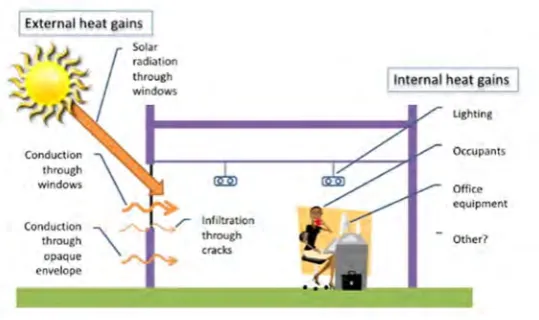
[image:19.595.199.469.234.394.2]Cooling load is energy must be removed from a space to maintain the temperature & humidity at the design values. When thermal loads push conditions outsider of the comfort range, HVAC systems are used to bring the thermal conditions back to the comfort conditions.There are several categories of load component which is external load, internal load and others load.
Figure 1: source of cooling load
External load is originated from outside heat source or unconditioned space from other space such as heat gain through wall and roof, solar heat gains from windows, conductive heat gain through fenestration and partition and infiltration of outdoor air. From a study in Hong Kong, solar heat gain via fenestration was dominated heat through inside building Solar which is 40% - 50% heat gain is come from solar radiation flow through fenestration. (Li & Lam, 2000).
Internal load is originated within space itself such as heat gain from people activities, electric light, equipment and appliances. Occupancy is effected the power of consumption in chiller system where University of Hong Kong was measure the power consumption by change the number of occupancy. The power at chiller is increased by increasing the occupancy.(Kwok, Yuen, & Lee, 2011).
6
2.2.1 Cooling load calculation
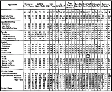
[image:20.595.155.529.322.627.2]Cooling load can be calculated by many type of method such as rule of thumb, cooling load temperature different (CLTD) and software. The calculation of cooling load was important to select the suitable system that should be installed to remove the load efficiently. The building cooling loads computed by simulation based on local weather data can form a good basis for plant sizing (Li, Wong, & Lam, 2003). Rule of thumb is the easiest way to find cooling load but not accurate as other method. Hence, rule of thumb is use in common to predict the cooling load of space. The calculation is only need area of selected space to calculate the cooling load.
7
2.2.2 Office cooling load
Private office cooling load is not much as factory and bigger space because of the area and volume of space is affected the cooling load. The bigger the space the bigger the area that expose to the sunlight and higher chances of external load to entering the space. Based on the rule of thumb table, private office occupancy is 150 ft2/person, lighting watt is 4 watt/ft2 and room sensible
is 25 btuh/ft2. By this data, cooling load of office room can be determined
depend on the size of office. Office cooling load is small then require small system to remove the sensible and latent heat inside the office which is 3000 btu/hr to 5000 btu/hr (SAHU, n.d.). Simulation of cooling load was run and office building contain 4267 btu/hr and require 0.6 Hp equipment to remove the load.(Lam & Li, 1999).
2.3 Thermal comfort
Human thermal comfort is the state of mind that expresses satisfaction with the surrounding environment. Thermal comfort is affected by body heat conduction, convection, type of clothes and rate metabolism of human. The state of thermal comfort of a person has a close relationship with physical and mental of themselves. Each person has different satisfaction on requirement of thermal comfort.
8
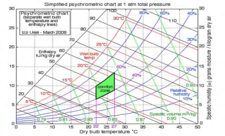
Figure 3: Psychometric chart of comfort zone (ASHRAE,2014)
Parameter Acceptable range in 8-TWA
Temperature (oC) 23-26
Relative humidity (%) 40-70
Air velocity (m/s) 0.15-0.5
*TWA= time-weighted average for up to 8hours/day
2.4 Air conditioning is used to provide thermal comfort zone
9
2.4.1 Basic cycle of refrigeration
The basic cycle of refrigeration is compressor will compress the gas phase of refrigerant. At this compression, the gas refrigerant will increase the temperature and pressure to the next component which is condenser. Condenser is a heat remover; the compressed gas will go through condenser and drop the temperature but the pressure is remained same. The gas refrigerant will turn into liquid refrigerant after through the condenser as the condensation process occurred.
Liquid phase of refrigerant will through an expansion valve, the temperature and pressure will drop at this point and straight to the evaporator. Evaporator is a heat absorber; the liquid phase of refrigerant through an evaporator, evaporation process occurred will change the liquid to gas phase and the temperature will slightly increase.(Wang, 2000).
10
2.4.2 Conventional unit use in office
There are possibilities of equipment that use to remove cooling load of office which mean a small amount of cooling load space. Most of air-conditioners used is low power consume such as split unit and portable air-conditioner as the sensible and latent heat contained in office is low. Commonly, the type of air-conditioner is an individual system which is self-contained in one packaged and factory-made air conditioner to serve one or two rooms. It uses vapour compression cycle directly to cool the indoor air for small loads. The comparison of these type air conditioner used from one brand which is Daikin. The specification of both air conditioner is the lowest cooling capacity type in one catalogue.
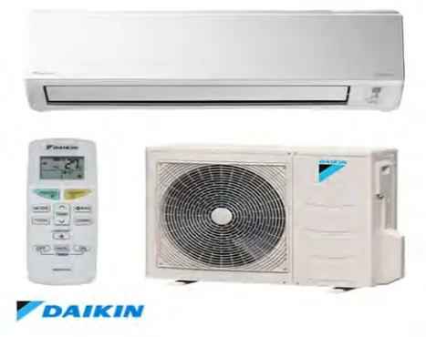
2.5 Split unit
[image:24.595.217.451.528.713.2]Split unit is the popular equipment for cooling purpose because of high efficiency. The ductless split system can cool for multiple zone. It is not requiring ducting like central system. the split unit have two section which is outdoor and indoor. Outdoor unit consist of condenser, expansion valve and compressor but indoor unit only consist of evaporator. All the data of the specification will be discussing is from Daikin Catalogue. (Daikin, 2015)