This is a repository copy of Integration and Application of Passive Cooling Within a Wind Tower.
White Rose Research Online URL for this paper: http://eprints.whiterose.ac.uk/80385/
Version: Accepted Version
Proceedings Paper:
Calautit, JKS, Hughes, BR and Ghani, SA (2014) Integration and Application of Passive Cooling Within a Wind Tower. In: ASHRAE, , (ed.) HVAC&R Research. First International Conference on Energy and Indoor Environment for Hot Climates , 24 - 26 February 2014, Doha, Qatar . Energy and Indoor Environment for Hot Climates , 160 - 167.
[email protected] https://eprints.whiterose.ac.uk/ Reuse
Unless indicated otherwise, fulltext items are protected by copyright with all rights reserved. The copyright exception in section 29 of the Copyright, Designs and Patents Act 1988 allows the making of a single copy solely for the purpose of non-commercial research or private study within the limits of fair dealing. The publisher or other rights-holder may allow further reproduction and re-use of this version - refer to the White Rose Research Online record for this item. Where records identify the publisher as the copyright holder, users can verify any specific terms of use on the publisher’s website.
Takedown
If you consider content in White Rose Research Online to be in breach of UK law, please notify us by
Calautit, J.K., Hughes, B.R. and S.A. Ghani. 2013. Integration and application of passive coling within a wind tower. First International Conference on Energy and Indoor Environment for Hot Climates, Doha, Qatar, 24 Feb 2014 - 26 Feb 2014
Integration and Application of Passive Cooling
Within a Wind Tower
John Kaiser Calautit 1, Ben Richard Hughes 1, Saud Abdul Ghani 2
1
School of Civil Engineering, University of Leeds, Leeds, UK
2
Department of Mechanical Engineering, Qatar University, Doha, Qatar
Abstract
Increasing emphasis on reducing power consumption has raised public awareness of natural and renewable energy resources, particularly the integration of passive cooling systems in buildings such as wind towers. Wind towers have been in existence in various forms for centuries as a non-mechanical means of providing indoor ventilation. In hot conditions where there is a relatively low difference between internal and external temperatures, the cooling capabilities of wind towers which depend mainly on the structure design itself are inadequate. Therefore it is essential to cool the air in order to reduce the building heat load and improve the thermal comfort of its occupants during the summer months. The aim of this work was to incorporate heat transfer devices in a wind tower to meet the internal comfort criteria in extreme external conditions. Heat transfer devices were installed inside the passive terminal of the wind tower unit, highlighting the potential to achieve minimal restriction in the external air flow stream while ensuring maximum contact time, thus optimising the cooling duty of the device. Computational Fluid Dynamics (CFD) modelling and experimental wind tunnel testing were conducted to investigate the performance of a wind tower system incorporating the heat transfer device arrangement. Results have indicated that the achieved indoor air speed was reduced by 28 – 52 % following the integration of the heat transfer device configurations. Furthermore, the study concluded that the proposed cooling system was capable of reducing the air temperatures by up to 12 K, depending on the configuration and operating conditions. Good agreement was observed between the CFD simulation and the experimental results.
1. Introduction
The increasing concern over end-user energy consumption has raised the public awareness of the climate change implications and generated interest in understanding the energy influences and the barriers to low energy use. The rising consumer demand exceeds the available clean energy supply and so green house gas emissions continue to increase. Buildings are at the centre of this problem. Commercial and residential buildings account for almost 30 - 40% of the world energy usage and are responsible for almost 40-50% of the global carbon emissions [1]. Extensive efforts have been focused on an environmentally friendly approach to building design revealing the on-going interest of the scientific community on the topic. Natural ventilation technologies such as wind tower devices are increasingly being employed in new buildings for increasing the fresh air rates and reducing energy consumption.
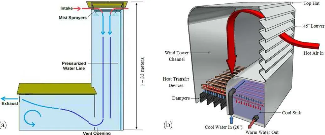
Wind towers have been in existence in various forms for centuries as a non-mechanical means of providing indoor ventilation, energy prices and climate change agendas have refocused engineers and researchers on the low carbon credentials of modern equivalents [1, 2]. A wind tower is a wind driven driven ventilation device which captures wind at high elevations and direct the air flow into the interior living spaces of the building, causing it to leave through windows or other exaust segments (Figure 1a). In hot and arid regions such as the Middle East, there is a huge dependency on electricity to run mechanical ventilation system and provide thermal comfort. In these areas, using wind towers to achieve comfort is a well-known technique. However, the cooling capabilities of wind towers which depend on the structure design itself are limited. Therefore it is essential to cool the air in order to reduce the building heat load and improve the thermal comfort of its occupants during the summer months [3].
An evaporative cooling wind tower is generally a tall structure mounted on top of a building. At the top of the tower, openings allows for air to enter. The induced warm air is passed through a wetted cloth or cooling pads, which holds water and allows air to flow through, evaporating the water in the process. The air passes through the cooling media, causing it to lower in temperature and thus becomes heavier and sinks to the bottom of the channel (Figure 1a). Other methods of evaporative cooling, such as the placement of water fountains, ground cooling, mist sprayers can also be integrated with wind towers [4]. Cooling wind towers are very large in scale and typically require integration into the architectural scheme of a building for aesthetic purposes. Also, high construction costs are associated with this system. Furthermore, evaporative coolers use a substantial amount of water to run. In some areas where water is expensive or in short supply, discarded water from the cooling tower can be an environmental concern.
A wind tower system incorporating heat transfer devices was designed to meet the internal comfort criteria in hot condtions (Figure 1b). The warm external air enters the wind tower through the louvers
angled at 45˚. The air flow is directed downwards and passed through a series of cylindrical heat transfer
The cooled air is supplied to the room below the channel via the ceiling diffusers which incorporates adjustable dampers to control the supply flow rate.
Figure 1 Flow diagram representing ventilation through an (a) evaporative cooling (b) heat transfer
device integrated wind tower.
2. Previous Related Works
Hughes and Cheuk-Ming [5] used experimental testing and CFD modelling to study the wind pressure
and buoyancy driven flows through a four-sided wind tower. The k-epsilon model with standard wall
functions was used for the numerical simulation. Hp-grid adaptation method was used to verify the computational grid. The numerical results were validated against full scale experimental testing and a good correlation between the different methods of analysis was observed. The study concluded that wind driven force is the primary driving force for the wind tower device, providing 76% more indoor ventilation than buoyancy driven forces.
Hughes et al. [1] reviewed the different cooling techniques integrated with wind tower systems to improve its thermal performance. Key parameters including the ventilation rates and temperature were evaluated in order to determine the viability of implementing the devices for their respective use. The results showed that the highest temperature reductions were achieved from incorporating evaporative cooling techniques into the wind tower such as wetted column (clay conduits) and wetted surface (cooling pads). The temperature reduction was found to be in the range of 12 –15 K. The study highlighted the importance of CFD and wind tunnel experimental methods for the analysis of wind tower devices.
standard wall functions was used for the numerical simulation. Grid adaptation was used to validate the programming and computational operation of the computational model. The numerical grid was refined and locally enriched using the hp-method grid adaptation technique. Results have shown that both systems were capable of supplying the required internal air supply rates however the reductions in internal temperature were insignificant (1-2 K). Therefore it is essential to cool the air in order to reduce the building heat load and improve the thermal comfort of its occupants during the summer months.
Calautit et al. [6] carried out a thorough investigation into a thermal comparison between evaporative cooling and heat transfer device integrated wind towers. Steady-state and three-dimensional CFD simulations, using standard k–e equations models, were carried out to predict the air velocity flow and
temperature distribution within the wind tower device. The work used a finite-volume discretisation
method and second-order upwind differencing scheme to achieve higher accuracy of the solutions. The numerical results for velocity and temperature showed a good agreement between the different sizes and types of grid distributions used. The study concluded that height was not a factor for the proposed design, making it highly viable for commercial wind towers.
Calautit et al. [7] also used CFD to compare the performance of a horizontal and vertical heat transfer device integrated wind tower system. Similarly, the turbulent nature of the flow was modelled by the standard k– e model. The work focused on the effects of the varying external wind speed on the ventilation and thermal performance of the proposed system. The wind tower was connected to a standard classroom with a recommended occupancy figure of 20 occupants. The study concluded that the system was capable of reducing the supply air temperature by up to 15 K, depending on the configuration and outdoor conditions. Furthermore, the study also highlighted that the proposed system was able to provide the recommended rates of fresh supply even at relatively low external wind speeds.
From the previous related work, the numerical simulation and experimental methods demonstrated the importance of the use of CFD in assessing the performance of wind towers. The good correlation between both methods of analysis suggests that the CFD techniques in use were suitable for this type of device and such have been used for the purpose of this research.
3. Computational Fluid Dynamics (CFD) Set-up
3.1 Physical domain
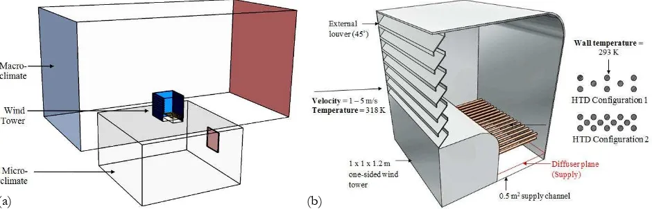
The CFD analysis was carried out using the ANSYS 13 FLUENT software. A flow domain representation of the physical geometry of the wind tower design under investigation and location of set boundary conditions are shown in Figure 2a. The enclosure was created to simulate the external wind velocity. The enclosure consists of a velocity inlet at the right hand side of the enclosure, and a pressure outlet on the opposing boundary wall of the macro climate. Figure 2b shows the schematic arrangements of the heat transfer devices that were incorporated to a one-sided wind tower. The work will investigate cooling potential of the proposed system and the effect of the addition of the cylindrical tubes on the air flow stream. Two heat transfer device configurations were simulated and compared; Configuration 1 (0.1 m horizontal spacing and 0.02 m vertical spacing) and Configuration 2 (0.05 mm horizontal spacing and 0.02 m vertical spacing) with 0.002 m dimater [8]. Detailed investigation of the performance of the cool sink is outside the scope of the study.
Figure 2 (a) Flow domain representation of the macro-micro climate (b) one-sided wind tower with the
heat transfer device arrangment.
3.2 Mesh Generation
The accuracy of the results achieved from the CFD modelling is highly dependent on the quality of the mesh, which equally have implications on the convergence of the model [5]. Due to the complexity of the wind tower geometry, the mesh generation type used was the combined tetrahedral/hybrid. This scheme specifies that the mesh is composed primarily of tetrahedral elements. The method also uses the hexahedral mesh where appropriate. A non-uniform mesh was applied to volumes of the computational models (Figure 3a). The grid was modified and refined around critical areas of interests in the simulation. The size of the mesh element was extended smoothly to resolve the sections with high gradient mesh and to improve the accuracy of the results of the velocity and temperature fields (Figure 3b).
[image:6.612.73.543.306.457.2]
Figure 3 (a) Computational mesh of the fluid domain (b) refined grid around the complex louver
section.
3.3 Boundary Conditions
[image:7.612.80.540.83.223.2]Table 1 summarises the CFD model boundary conditions. Test were performed for various external wind speeds (0 - 5 m/s). A constant inlet temperature of 318 K was set to simulate a hot outdoor environment. In order to cool the induced air, wall temperature of 293 K (operating temperature) was applied to the heat transfer device surface.
Table 1 Summary of boundary conditions
Boundary condition Type/set values
Discretisation scheme second-order upperwind
Time steady state
Viscous model k-epsilon
Velocity inlet [m/s] 1 – 5 m/s
Pressure outlet [Pa] atmospheric
Inlet temperature [K] 318 K
Heat transfer devices wall temperature [K] 293 K
3.4 Grid adaptation
Grid adaptation method was used to validate the programming and computational operation of the computational model. The numerical grid was refined and locally enriched using the hp-method grid adaptation technique [5]. This procedure of evaluation requires the use of different mesh by the use of a posterior error estimates. The grid was evaluated and refined until the posterior estimate error becomes insignificant between the number of nodes and elements and the posterior error indicator [9]. Figure 4 shows that at 6,049,235 elements the percentage error between the grid refinements was at its lowest for the benchmark model. The error between the grid refinements was at its lowest in the last two steps for the horizontal HTD wind tower. An acceptable compromise was reached between the accuracy of results and computational iterations.
[image:7.612.81.532.372.496.2]Figure 4 Posterior error on the average velocity in the test room using the h-p grid adaptation method.
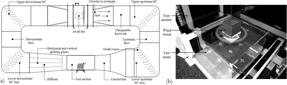
4. Wind Tunnel Experimental Set-up and Measurement Procedure
In this study, a 3D printed 1:10 scale model of the heat transfer device integrated wind tower was employed. The experimental investigations were conducted in an closed-loop low speed wind tunnel located in the School of Civil Engineering of the University of Leeds, UK. The wind tunnel was designed for the experimental testing of natural ventilation systems in buildings. The wind tunnel consisted of an overall plan length of 5.6 m with a test section of the height, width, and length of 0.5, 0.5, and 1 m (Figure 5a). The 1:10 wind tower scale model was connected to a 0.5 x 0.5 x 0.3 m test room with an outlet window, which was mounted underneath the wind tunnel test section. In this study the airflow inside the test room model was measured using the hot-wire anemometer. Nine data points in an equally spaced 3 by 3 grid were created within the test room at a height of 1.5 m which allowed for measurements to be made for velocity within the test room (Figure 5b). Additionally, three data points were positioned at the bottom of the room and below the supply of the wind tower.
Figure 5 (a) Schematic of the closed-loop wind tunnel system (b) 3D printed wind tower model inside
the wind tunnel test section.
The uncertainties associated with the velocity, the hot wire probe (Testo 425) gave velocity measurements with uncertainty of ±1.0 % rdg. at speeds lower than 8 m/s. In order to recognise the flow
0.00 0.05 0.10 0.15 0.20 0.25 0.30 0.35
1,540,000 2,540,000 3,540,000 4,540,000 5,540,000 6,540,000
E
rr
o
r
p
er
ce
n
tag
e
(%)
Number of elements
Benchmark Wind Tower
Horizontal HTD Wind Tower
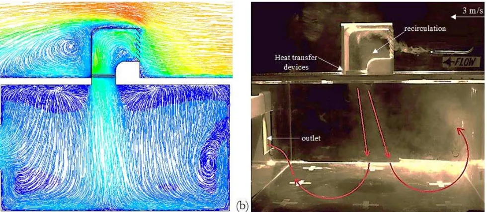
[image:8.612.69.528.87.207.2] [image:8.612.57.555.464.612.2]pattern in and around the wind tower model, smoke visualisation tests were also carried out. The side wall of the wind tower model and the test room were built of acrylic perspex to visualise the internal flow. The model was exposed to a free stream air velocity of 3 m/s to obtain smoke of a sufficiently high concentration.
5. Results and Discussion
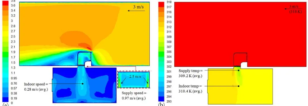
Figure 6a illustrates the velocity contours of the cross sectional plane in the test room model with the heat transfer device integrated wind tower. As seen in the illustration, the air flow enters from the right side of the enclosure passing around the wind tower with some of the air induced inside the channel and exiting to the pressure outlet. The flow entering the wind tower speeds up as it enters the device reaching maximum velocity of 2.3 m/s as it hits the rear wall of the channel and forces the flow down into the test room. At an inlet velocity of 3 m/s, the average velocity at the wind tower diffuser was 0.97 m/s while the average velocity in the microclimate was obtained at 0.28 m/s. Figure 6b depicts the temperature distribution inside the test room with a heat transfer devices integratecd wind tower. The average temperature inside the microclimate was 310.4 K with the macro climate temperature set at 318 K. A greater temperature reduction was obtained at the immediate downstream of the heat transfer devices with a supply temperature value of 309 K. The results displayed that the heat transfer devices had the capability of reducing temperatures of the induced air stream.
Figure 6 (a) Velocity and (b) temperature contour of a midplane inside the test room with a heat transfer
device integrated wind tower.
[image:9.612.59.553.382.552.2](configuration 1) – 6 K (configuration 2). Significant reduction in temperature was observed at lower wind speeds (1 – 2 m/s), up to 4 – 6 K (configuration 1) and 9.5 – 12 K (configuration 2).
Figure 7 Comparison between average indoor (a) velocity and (b) temperature at various external wind
speeds.
Figure 8 displays a comparison between CFD and experimental visualised flow pattern inside the test room model. A similar flow pattern was observed; the airflow exiting the wind tower channel was directed towards the floor of the test section and spread outwards in all directions. As the airflow hits the bottom surface the air slows down and flows through the side walls, with some of the air escaping through the window opening.
Figure 8 Comparison between the (a) CFD velocity streamlines and (b) smoke visualisation inside the
test room. 0 0.1 0.2 0.3 0.4 0.5 0.6 0.7 0.8 0.9 1
1 2 3 4 5
A v era g e v elo cit y (m /s)
External wind speed (m/s)
Benchmark (no HTD)
Wind tower with HTD (Config 1) Wind tower with HTD (Config 2)
304 306 308 310 312 314 316 318
1 2 3 4 5
A v er ag tem p er atu re (K)
External wind speed (m/s)
Indoor Temperature (Config 1) Indoor Temperature (Config 2)
External temperature = 318 K
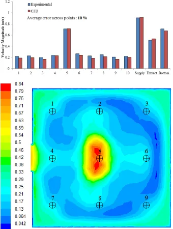
[image:10.612.68.558.442.655.2]Figure 9a shows a comparison between the experimental and CFD results for the velocity measurements. It can be observed that the CFD slightly underestimated the airflow speeds for most of the points. The trend shows that the CFD model was capable of predicting the airflow inside the test room. Average error across the points was 10 %. Figure 9b displays the velocity contours from plan view of the microclimate with a standard wind tower model. As expected, maximum velocity was achieved at the centre of the room with a maximum value of 0.84 m/s. A uniform trend was achieved across the other sides of the domain as the velocity decreased to an average value of 0.28 m/s across the remaining vertices.
Figure 9 (a) Comparison between the experimental and CFD results for indoor velocity with external
[image:11.612.136.476.219.669.2]6. Conclusions
A numerical and experimental investigation was carried out to investigate the thermal performance of a wind tower integrated with heat transfer devices. A standard one-sided wind tower was used as a benchmark model. The numerical model was validated against wind tunnel experimentation and good correlation was achieved between the two parameters with the error below 10 %. Furthermore, the findings of the study displayed that the proposed wind tower was capable of reducing temperatures by up to 12 K within the microclimate depending on the external velocity of the airstream. The work highlighted the potential of integrating heat transfer devices into wind towers in reducing the temperature of air induced into the ventilated space.
Acknowledgement
This paper was made possible by a NPRP grant from the Qatar National Research Fund (A member of the Qatar Foundation). The statements made herein are solely the responsibility of the authors. NPRP 09-138-2-059. The technology presented here is subject to IP protection under the QNRF funding guidelines.
References
[1] Hughes, B.R., Calautit, J.K., and S.A. Ghani. 2012. The Development of commercial wind towers for natural ventilation: A review. Applied Energy, 92: 606-627.
[2] Calautit, J.K., Hughes, B.R. and S.A. Ghani. 2013. Numerical investigation of the integration of heat transfer devices into wind towers, Chemical Engineering Transactions, 34: 43-48.
[3] Calautit, J.K., Hughes, B.R. and S.A. Ghani. 2013. Numerical investigation into the feasibility of integrating green building technologies into row houses in the Middle East. Architectural Acience Review, 56: 279-296.
[4] Calautit, J.K., Hughes, B.R., Chaudhry, H.N. and S.A. Ghani. 2012. Computational analysis of a heat transfer device integrated wind tower system. The 7th Sustainable Development of Energy, Water and Environment Systems (SDEWES 2012), Ohrid, Macedonia.
[5] Hughes, B.R. and M. Cheuk-Ming. 2011. A study of wind and buoyancy driven flows through commercial wind towers. Building and Environment, 43: 1784-1791.
[6] Calautit, J.K., Chaudhry, H.N., Hughes, B.R. and S.A. Ghani. 2013. Comparison between evaporative cooling and a heat pipe assisted thermal loop for a commercial wind tower in hot and dry climatic conditions. Applied Energy, 101: 740-755.
[7] Calautit, J.K., Hughes, B.R., Chaudhry, H.N. and S.A. Ghani. 2013. CFD analysis of a heat transfer device integrated wind tower system for hot and dry climate. Applied Energy, 112: 576-591.
[8] Hughes, B.R., Chaudhry, H.N. and J.K. Calautit. 2013. Passive energy recovery from natural ventilation air streams. Applied Energy, 113: 127-140