COMPARATIVE STUDY ON DIFFERENT APPROACH OF BOOTHROYD DEWHURST (B-D)
DESIGN FOR ASSEMBLE (DFA) TECHNIQUE
AHMAD SHAFIE BIN RAZAK
SUPERVISOR DECLARATION
“I hereby declare that I have read this thesis and ensure that this thesis is sufficient in term of scope and quality for the award of the degree of
Bachelor of Mechanical Engineering (Design and Innovation)”
Signature: ………
Supervisor: Mr. Mohd Ruzi bin Harun
DECLARATION
“I hereby declare the work in this thesis is my own except for summaries and quotation which have been duly acknowledgement”
Signature: ………...
Author: Ahmad Shafie bin Razak
Date: ………...
ACKNOWLEDGEMENT
The student name Ahmad Shafie Bin Razak would like to dedicate his gratitude to all person involve in completing the report and PSM study directly or indirect. Especially to UTeM (Universiti Teknikal Malaysia Melaka), that provides coarse Degree of Bachelor of Mechanical Engineering Design and Innovation (BMCD).
Furthermore, thanks to the supervisor Mr.Mohd Ruzi bin Harun for his guidance and advice during industrial training. Thanks also go to the other staffs of UTeM, and technicians and fellow friends that help to guide during handle the project and managing the work.
ABSTRACT
Boothroyd Dewhurst (B-D) Design for Assembly (DFA) is method used to measure the assembly efficiency during assembly process in industry. There are two approach in B-D DFA which are manual approach and software approach. Both approaches have their own standard on the assembly evaluations which have cause differences in the results. The software approach is systematically formulated from the manual approach. Therefore the DFA of design efficiency is supposed to be equal or at least a little error percentage between them. The percentage error might be due to misjudgement during part assembly. Therefore the study the factor that affect the percentage error of design efficiency between manual approach and software approach of Boothroyd Dewhurst (DFA) perform and analyse in order to understand the function of these method in evaluate the product. The Manual approach follow the table in “Product Design for
Manufacturing and Assembly “ third edition by G. Boothroyd, P. Dewhurst and W,A, Knight. (copyright Boothroyd Dewhurst 1999, Inc) .The software approach use the Boothroyd Dewhurst (DFA) Design for Assembly 9.3(2006).The result than analyse and compare to evaluate the percentage difference and determine the reason for the difference to occur.
ABSTRAK
Boothroyd Dewhurst (BD) Rekabentuk untuk Pemasangan (DFA) adalah kaedah yang digunakan untuk mengukur kecekapan pemasangan semasa proses pemasangan diindustri. Terdapatdua pendekatan dalam B-D DFA iaitu pendekatan manual dan pendekatan perisian. Kedua-dua pendekatan mempunyai standard yang tersendiri pada penilaian pemasangan yang mempunyai meyebabkan perbezaan dalam dapatan kajian. Pendekatan perisian dirumuskan secara sistematik merujuk pendekatan manual. Oleh itu DFA kecekapan rekabentuk sepatutnya sama atau lebih kurang peratusan ralat sedikit di antara mereka. Kesilapan peratusan mungkin disebabkan oleh salah tafsir semasa perhimpunan bahagian. Oleh itu faktor yang memberi kesan akan dikaji tentang ralat peratusan kecekapan rekabentuk antara pendekatan manual dan pendekatan perisian Boothroyd Dewhurst (DFA) untuk melaksanakan dan menganalisis bagi memahami fungsi kaedah ini dalam menilai produk. Pendekatan Manual mengikut jadual di dalam "Design Produk untuk Pembuatan dan Dewan" edisi ketiga oleh G. Boothroyd, P.Dewhurst dan W, A, Knight. (hakcipta Boothroyd Dewhurst 1999, Inc) .Manakala pendekatan perisian
TABLE OF CONTENT
CHAPTER TITLE PAGE
Dedication v
Acknowledgement v
Abstract v
Abstrak v
Table of Content v
List of Table vi
List of Figure ix
List of Symbol v
List of Appendix v
I. INTRODUCTION
1.1 Problem Statement 1
1.2 Objective 2
1.3 Scope 2
1.4 Significant 2
1.5 Summary 3
II. LITERITURE REVIEW
2.1 Introduction 4
2.2 Design For Manufacturing an Assembly DFMA 4
2.3 Design for Assembly(DFA) 8
2.3.1 Manual Approach 8
2.3.2 Software Approach 12
2.3.3 DFA Assembly Efficiency 14
2.4 Design for Assembly (DFA) Guidelines 15
2.5 Computer Aided Design CAD 16
2.6 Summary 17
III. METHODOLOGY
3.1 Introduction 18
3.2 Data Gathering 18
3.4 Product Design Modelling 20
3.5 Product Structure Three 21
3.6 Analysis of DFA Using Manual Approach 22
3.7 Analysis of DFA Using Software Approach 24
3.8 DFA Score and Evaluation 24
3.9 Summary 25
IV. PRODUCT CASE STUDY
4.1 Introduction 26
4.2 Case Study 26
4.3 Specification of original Product 27
4.4 Theoretical and Non-Theoretical Part Selection for Original Product.
27
4.5 Parts Information in the Original Product 29
4.6 Product Tree for Original Product 35
4.7 Approach of Boothroyd Dewhurst for Original Product 36
4.71 Manual Approach Original Product 36
4.72 Software approach Original Product 39 4.73 Manual and Software Comparison and Evaluation
for Original Product
41
4.8 Part Critique 42
4.9 Suggestion on Improvement 43
4.10 Parts Information in the Redesign Product 43
4.11 Product Tree for Redesign Product 48
4.12 Approach of Boothroyd Dewhurst for Redesign Product
49
4.12.1 Manual Approach Redesign Product 49 4.12.2 Software approach Redesign Product 51 4.12.3 Manual and Software Comparison and Evaluation
for Redesign Product
53
4.13 Summary 54
V. RESULT AND DICUSSION
5.1 Comparison of Manual Approach and Software Approach Design Efficiency
5.1.1 Manual Approach Original and Redesign Comparison
56
5.1.2 Software Approach Original and Redesign Comparison
57
5.1.3 Comparison of Data 58
5.2 Consideration of Related Parties Involved In DFA Analysis and Product Design
59
5.3 Opinion of the Study 60
5.4 Chapter 5 Summary 60
VI. CONCLUSION AND RECOMMENDATION
6.1 Conclusion 61
6.2 Recommendation 62
BIBLIOGRAPHY 63
LIST OF TABLE
TABLE TABLE PAGE
NO.
3.1 Theoretical part evaluation 22
3.2 Part Information 23
3.3 Manual analysis table 23
3.4 The sample example of case study results. 25
4.1 Parts classification for Theoretical parts and Non theoretical parts
28
4.2 Original Handle Component 30
4.3 Original Back Body Component 31
4.4 Original Main Body Component 33
4.5 Original Product DFA Manual Analysis Table 36 4.6 Data collected by using DFA Software approach
Original Product
40
4.7 The percentage differences of Manual Approach and Software Approach
42
4.8 Redesign Handle Component 44
4.9 Redesign Back Body Component 45
4.10 Main Body Component 47
4.11 Redesign Product DFA Manual Analysis Table 49
4.12 Data collected by using DFA Software approach
Redesign Product
52
4.13 The percentage differences of Manual Approach and
Software Approach
53
5.1 Manual Approach Assembly comparison for original design product and redesign product
57
5.2 Software Approach Assembly comparison for original design product and redesign product.
LIST OF FIGURE
FIGURE TITLE PAGE
No.
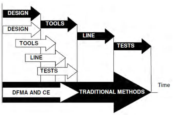
2.1 Time to Deliver Comparison between DFMA +
Concurrent Engineering (CE) and the Traditional ( Pedro (2006)
5
2.2 “Over the Wall Design” (Boothroyd.G ,1992) 6
2.3 Effect of DFMA on cost product (Boothroyd , 2002) 6 2.4 DFMA shortens the design process(G. Boothroyd, 2002) 7 2.5 Selected manual handling time standards, seconds (parts
are within easy reach, are no smaller than 6mm, do not stick together, and are not fragile or sharp).(Copyright 1999 Boothroyd Dewhurst, Inc.)
10
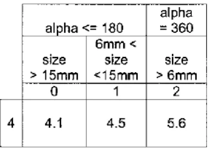
2.6 Selected manual insertion time standards, seconds (parts are small and there is no resistance to insertion).
(Copyright 1999 Boothroyd Dewhurst, Inc.)
11
2.7 Selected separate operation times, seconds (solid parts already in place). (Copyright 1999 Boothroyd Dewhurst, Inc.)
11
2.8 Alpha and beta rotational symmetries for various parts 12
3.1 Original Product Modelling 21
3.2 Sample of product structure three 21
3.3 The example software of part assembly evaluation 23
4.1 Easy Storage Trolley Before and after fold 26
4.2 Product Tree Original Product 33
4.3 Structure Chart Original Product in the Software 37 4.4 DFA index and production data of product original design
result from DFA software approach.
38
4.5 Product Design for Redesign product 41
4.6 Redesign Product Tree 46
4.7 Structure Chart Redesign product in the Software 49 4.8 DFA index and production data of product redesign result
from DFA software approach.
A Manual Handling Time 64
B Manual Insertion Time 65
C Gantt chart PSM 1 66
D Gantt chart PSM 2 67
E Flow Chart 68
LIST OF SYMBOL
α Alpha = orientation of part in X-axis
β Beta = orientation of part in Y-axis
DFMA Design for Manufacturing and Assembly
DFA Design for Assembly
B-D Boothroyd Dewhurst
𝐍𝐦𝐢𝐧 Theoretical Minimum Number of Parts 𝐭𝐦𝐚 Total Manual Assembly Time
𝐭𝐚 Basic Assembly Time for One Part Standards
𝐄𝐦𝐚 DFA Index
LIST OF APPENDIX
APPENDIX TITLE PAGE
NO.
A Manual Handling Time 64
B Manual Insertion Time 65
C Gantt chart PSM 1 66
D Gantt chart PSM 2 67
E Flow Chart 68
F Design for Assembly Suggestion for Redesign for Original Product
CHAPTER 1
INTRODUCTION
1.1 PROBLEM STATEMENT:
Design for Assembly is a tool or method for industry to reduce time and cost of assembly product in the same time can improve the quality of the product. Design for Assembly as the basic concurrent engineering studies to provide guidance to the design team in simplifying the product structure, to reduce manufacturing and assembly cost, and to quantify the improvement because before this most of them using an over the wall approach. Design for assembly also as a benchmarking tool to study competitor’s products and quantify manufacturing and assembly difficulties
There are two approaches in Boothroyd Dewhurst (B-D), Design for Assembly (DFA) evaluation namely manual approach and software approach. The software approach is systematically formulated from the manual approach. Therefore the DFA of design efficiency is supposed to be equal or at least a little error percentage between them. The percentage error might be due to misjudgement during part assembly.
1.2OBJECTIVE
To study the factor that affect the percentage error of design efficiency between manual approach and software approach of Boothroyd Dewhurst (DFA). Therefore, both approaches need study, perform and analyse in order to understand the function of these method in evaluate the product.
Therefore by carrying out the study, the understanding Boothroyd Dewhurst method either manual approach or software approach needs to be study, understand and carry out by study a product. The action need to be follow by referring a reliable source such of books, journals, experience person and reliable internet resources
1.3 SCOPE
The scopes of these studies are:
1. To evaluate the existing product design efficiency using manual approach of
B-D DFA.
2. To apply DFA software analysis on the same existing product design.
3. To compare both approaches product design efficiency.
4. To study the factors that contributed to the design efficiency error.
5. To re-evaluate the design efficiency based on the identified contributed factors.
6. To redesign the product by referring the B-D DFA guideline.
7. To Re-evaluate the redesign product using manual and software of B-D DFA.
1.4 SIGNIFICANT OF PROJECT
The purposes of Design for Assembly (DFA) are to make the process of fabrication and assembly easier, and reduce the cost. It will also simplify the product and also make the product become more reliable. If the engineers carry out their design in order to achieve Design for Assembly (DFA) analysis, they can protect product function and will know and determine that there is little chance that function will be seriously impaired.
There are several methods that widely used in industry to achieve Design for Assembly (DFA). The most widely used in industry nowadays is Boothroyd Dewhurst method, Hitachi Assembly Evaluation Method, Effort Flow Analysis and Lucas Hull method. However, in this project will only focus on Design for Assembly using Boothroyd Dewhurst methods which consist of manual approach and software approach product design efficiency comparison.
The case study of this project is more on product design efficiency analysis on both method of manual approach and software approach by using easy storage trolley. The target of this analysis is to evaluate score product design efficiency for each part before and after redesign. The product will be redesign with the same function and shape with simpler assembly method. It will make comparison become clearer.
1.5SUMMARY
CHAPTER 2
LITERITURE REVIEW
2.1 Introduction
The purpose of this chapter is to provide information and review about the Design for Manufacturing and Assembly (DFMA). This chapter will discusses about the following sub-chapters; design for manufacturing and assembly, theory of manual and software approach, review on previous case studies and perspective approach.
2.2 Design for Manufacturing and Assembly of Boothroyd Dewhurst.
The main activities of the DFMA are concurrent engineering to provide guidance to design team in simplifying the product structure, to reduce manufacturing and assembly costs and to qualify improvements. Besides, it is also used as a benchmarking tool to study competitors’ products, and as a should-cost tool to negotiate contract with the supplier as shown figure 2.1.
Figure 2.1:Time to Deliver Comparison between DFMA + Concurrent Engineering (CE) and the Traditional (Pedro (2006)
Boothroyd.G, (1992) have stated. “We design it, you build it." This attitude has now become known as "over-the wall" design which means the designer did not care about the manufacturing engineer, they think that their responsibility is to draw and design the drawing then after that throw all the drawing to aside for manufacturing engineer as shown in figure 2.2. They are facing a lot of manufacturing problem because they were not involved in design effort
Figure 2.2: “Over the Wall Design” (Boothroyd.G ,1992)
Boothroyd (2002) have said that product design manufacturing and assembly (DFMA), it have been developed and discovered applied in industry particularly U.S. industry. In fact, it can be said that the availability of these methods have created a revolution in the product design business and helped to break down the barriers between design and manufacture; it has also allowed the development of concurrent or simultaneous engineering as shown in figure 2.3 and figure 2,4.
[image:19.595.151.466.523.721.2]Figure 2.4: DFMA shortens the design process (G. Boothroyd, 2002)
In study of De Fazio T. L. (1993), the DFMA would be a workstation -like environment at which a designer could create a design in terms beyond just geometry, and accessing to capabilities for design trade-off studies, cost reduction studies, reducibility evaluations, design rule checking, and manufacturing and assembly evaluations and recommendations. It will act like a manufacturing expert looking over the designer's shoulder, providing a god suggestions, comments about the design and the defect of the design pattern, and information about fabrication and assembly.
2.3 Design for Assembly (DFA)
The development of the original design for assembly method is early on 1960s on automatic handling. A group technology classification system was developing to catalogue automatic handling solutions for small parts. This shows that classification system could help the designers to design parts that would be easy to handle. University of Salford in England also was awarded a government grant to study product design for automatic assembly in the middle 70s (G.Boothroyd, 2002).
Design is a complex iterative creative process that begin with the recognition of a need desire and terminates with a product or process that uses available resources, energy and technology to fulfil the original need within some set of defined constraint. Assembly is a process of joining components into complex product.
Design For Assembly (DFA) is an approach to reduce the cost and time of assembly by simplifying the product and process through such means as reducing the number of parts, combining two part into one part, reducing or eliminating adjustments, simplifying assembly operations, designing for part handling, selecting fasteners for ease of assembly and minimizing parts tangling.
The purposes of DFA are to design a product for easy and economical production and also incorporate product design early in the design phase. Besides, by using Design for Assembly it can improve quality, reduces cost and shortens time to design and manufacture.
2.3.1 DFA Manual approaches
The manual provides cooperatives and other types of self-help organizations with practical guidance that viable. It covers all the steps of project design: from the identification of the evaluation of each part in product, to determine the required time for assembly by referring the evaluation set for each part. For example manual assembly chosen as selected for manual approach time determination, have its own specification been determined that need to follow which same goes to the other type of assembly.
The portion of the classification system for manual insertion and fastening processes is concerned with the interaction between mating parts as they are assembled. Manual insertion and fastening consists of a finite variety of basic assembly tasks (peg-in-hole, screw, weld, rivet, press-fit, etc.) that are common to most manufactured products. If applied properly, these criteria require the designer to consider means whereby the product can be simplified, and it is through this process that enormous improvements in assemble ability and manufacturing costs are often achieved. However, it is also necessary to be able to quantify the effects of changes in design schemes. For this purpose the DFA method incorporates a system for estimating assembly cost which, together with estimates of parts cost, will give the designer the information needed to make appropriate trade-off decisions.
a. parts that can be lifted with one hand but require two hands because they severely nest or tangle, are flexible or require forming etc
Figure 2.5: Selected manual handling time standards, seconds (parts are within easy reach, are no smaller than 6mm, do not stick together, and are not fragile or sharp).
c. part inserted and secured immediately by screw fastening with power tool (Times are for 5 revs or less and do not include a tool acquisition lime of 2.9s)
Figure 2.6: Selected manual insertion time standards, seconds (parts are small and there is no resistance to insertion).
(Copyright 1999 Boothroyd Dewhurst, Inc.)
Figure 2.7: Selected separate operation times, seconds (solid parts already in place). (Copyright 1999 Boothroyd Dewhurst, Inc.)
I. Alpha is the rotational symmetry of a part about an axis perpendicular to its
axis of insertion. For parts with one axis of insertion, end-to-end orientation is necessary when alpha equals 360 degrees, otherwise alpha equals 180 degrees.
II. Beta is the rotational symmetry of a part about its axis of insertion. The
[image:24.595.155.489.373.494.2]