International Journal of Innovative Technology and Exploring Engineering (IJITEE) ISSN: 2278-3075, Volume-8 Issue-7, May, 2019
MPPT and Pitch Angle Control of a Permanent
Magnet Synchronous Generator based Wind
Emulator
Rania Moutchou, Ahmed Abbou
Abstract: This work aims at studying the interconnection characteristics of a wind turbine based on a permanent magnet synchronous generator (PMSG) from a wind turbine emulator. The goal is to make a maximum power point tracking (MPPT) analysis and pitch angle control. In first place, wind turbine modeling is done using a DC machine. Then, a maximum power technique MPPT and a wedging angle control strategy will be developed in order to adapt turbine speed to wind speed to maximize and limit power output of the wind turbine (WT). Results of simulation are given to show the performance and the effectiveness of the proposed controls, regarding reference tracking, sensibility to high wind speed variations and unavailability of turbine parameters. The complete system model will be developed in the Matlab/Simulink environment.
Keywords: MPPT, pitch angle, DC machine, wind turbine emulator, PMSG.
I. INTRODUCTION
Recently, the global energy consumption has seen an enormous increase due to the massive industrial development, which tends to increase in size. China is one of the world’s countries which represent a remarkable case of this increased consumption of energy. The risks of scarcity of fossil fuels and their effects on climate change once again highlight the importance of renewable energies, particularly the wind turbine which has been identified as one of the most promising. The evolution of the wind turbine has grown in recent years, which has been given enormous attention as a privileged technology that represents an interesting alternative especially for the production of electrical energy. In this paper, we focus on the variable speed wind energy conversion system (WECS) due to its many advantages, such as a reduced torque oscillations and mechanical stress and a better exploitation of available wind energy compared to the fixed speed WECS. In this paper, we aim to study the interconnection characteristics of a permanent magnet synchronous generator based wind turbine from a wind turbine emulator based on the principle of control of a DC machine. The main objective is to develop a MPPT control method in order to adapt the speed of the turbine with respect to the wind speed, in order to maximize the converted power, this will improve their integration to the electrical networks.
Revised Manuscript Received on May 06, 2019
Rania Moutchou, Mohammadia School of Engineers (EMI), Research team in Electrical Energy and Control (RTEEC), Mohammed V University, Rabat, Morocco.
Ahmed Abbou, Mohammadia School of Engineers (EMI), Research team in Electrical Energy and Control (RTEEC), Mohammed V University, Rabat, Morocco.
On the other hand, the pitch angle control is employed to protect the WT against overloading in the case of high wind speed. The performances of the proposed controllers system were tested, analyzed using Matlab/Simulink Software.
1. CONVERSION OF WIND ENERGY
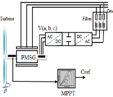
[image:1.595.325.561.289.492.2]The WECS proposed is represented on the Fig. 1. A wind turbine is a device that captures the kinetic energy of the wind and converts it into mechanical energy.
Figure 1: Wind energy conversion system (WECS).
A. Wind modeling
The wind speed at a point can be broken down into two components: a slowly varying average, and the other with fluctuations such as:
(1) With, is the average value of the slow component, and is the fluctuations caused by turbulence.
Fluctuations in wind speed must be treated statistically. The standard deviation describes the variability of the wind and is defined as follows:
(2)
MPPT and Pitch Angle Control of a Permanent Magnet Synchronous Generator based Wind Emulator
Figure 2: Synoptic diagram of wind reconstruction.
B. Wind turbine system modeling
The modeling of the wind turbine is the greatest part for a WECS. The modeling of the turbine must be made to collect the maximum kinetic energy of the wind with lower costs.
The captured aerodynamic power can expressed as:
(3) And, the torque collected by the wind turbine is given by the following relation:
(4) Where,ρ,S and V represent respectively the density of air, the surface swept by the blades and the wind speed.
In our case, the variations of Cp(,) are modeled by the following exponential approximation:
(5)
With:
1 β 0.035 β 0.08 λ
1 λ
1
3
i
And is the pitch angle of the blades.
Where, present the relationship between the linear velocity of pale and the speed of the wind which can be expressed as follows:
(6) With R the ray of pale of the wind, reactivity power coefficient andΩ
t
he angular a velocity of the turbine.-depend on the particular turbine and the values are given in table 1.
TABLE 1:COEFFICIENT DEFINING THE EVOLUTION OF CP.
COEFFICIENT VALUE
0.5109
116
0.4
5
21
0.0068
[image:2.595.45.302.72.175.2]Fig. 3 represents the power coefficient curves as a function of λ for different values of β. The maximum value of Cp(Cpmax=0.48) is achieved for λopt=0.014 and 0.
Figure 3: Power coefficient as a function of λ.
[image:2.595.325.547.164.345.2]The characteristic of the optimum power of a wind turbine is strongly nonlinear. For each wind speed, the system should always find the maximum power, which requires controlling the speed of the WT to be equal to its optimum one. It is clear from Fig. 4that the mechanical power is maximized at particular rotational speed for each wind speed.
Figure 4: The power of the wind turbine.
We take the aerodynamic torque in this case is equal to the torque of the fast shaft:
(7) The fundamental equation of the dynamic makes it possible to determine the development of the rotational speed from the mechanical torqueCmec available on the rotor of the machine.
(8)
m
and J represent
respectively the mechanical speed and moment of inertia.
V0
V
White Noise
Gaussian Low Pass Filter
Average Speed
[image:2.595.328.562.463.594.2] [image:2.595.98.239.662.785.2]MPPT and Pitch Angle Control of a Permanent Magnet Synchronous Generator based Wind Emulator
The mechanical torque is given bythe following relation: (9) Where, Cem is the electromagnetic torque and f is a viscous friction coefficient.
[image:3.595.320.559.51.181.2]2. EMULATION BY ASSOCIATION OF THE DC MACHINE The DC machine is reversible; it works as a motor if the torque and speed are of the same sign and generator if the torque and speed are contrary signs. Fig. 5 shows the association of the MCC with the system.
Figure 5: The MCC with the system.
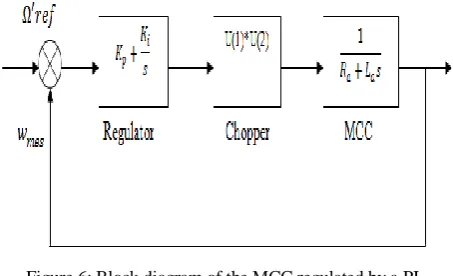
[image:3.595.51.294.198.297.2]From a methodological point of view, the control of the DC motor is very important and it is done by a chopper + regulator shown in Fig. 6.
Figure 6: Block diagram of the MCC regulated by a PI.
A. Modeling of the DC machine
The DC machine can be modeled through electrical, electromechanical and mechanical equations.
The electrical equations of the machine are: For the excitation circuit
(10) For the armature circuit
(11) The mechanical equation is given by:
(12) With the resistant torque, the coefficient of friction, the Moment of inertia.
In our case, the machine is separate excitation, the flux created by the inductor winding is constant. We then have:
(13) From the electrical (armature) and mechanical equations, the block diagram of the model of the DC machine is shown in Fig. 7.
Figure 7: Block diagram of the MCC with constant flow.
B. Synthesis of the integrated proportional regulator (PI)
After modeling the DC machine, we will then develop the synthesis of the proportional-integral (PI) controller used to control the DC machine.
[image:3.595.63.290.364.502.2]The regulator (PI) is given by the following Fig. 8:
Figure 8: Regulator P.I.
The transfer function will be:
(14) 3. MPPT CONTROL WITHOUT MECHANICAL SPEED
CONTROL
The purpose of variable speed control is to extract the maximum power of the wind turbine. For that, we need algorithm acting on set point variables to get the best return possible of the device. Through the bibliography study, we distinguished two families control structures for maximizing extracted power:
MPPT control without mechanical speed control; MPPT control with mechanical speed control. In our case, the technique used for extracting the maximum power is MPPT without mechanical speed control,this mode of control is based on the assumption that the wind speed varies verylittle steady state in front of the system's electrical time constantswind turbine, which implies that the acceleration torque of the turbine can be consideredlike no one. In this case, from the mechanical equation, we can write:
[image:3.595.49.293.565.702.2]
MPPT and Pitch Angle Control of a Permanent Magnet Synchronous Generator based Wind Emulator
viscous friction compared to the mechanical torque , we can then write:
(16) The electromagnetic torque is determined from an estimate of the torquewind turbine:
(17) The wind turbine torque is itself estimated according to the wind speedand the speed of the turbine:
(18) An estimate of the speed of the turbine is calculated from the speedmechanical:
(19)
The estimate of the wind speed is then expressed by:
(20) From these relationships we have:
(21) To extract the maximum power generated, it is necessary to set the speed ratioat which corresponds to the maximum of the power coefficient .
The estimated electromagnetic torque must then be set to the following value:
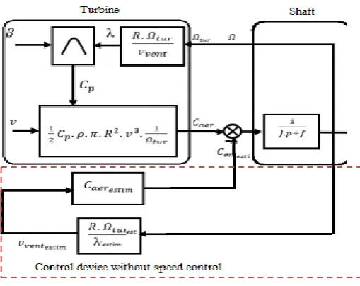
(22) Fig. 9 shows the principle of MPPT control of the wind turbinewithout slaving of the speed of rotation:
Figure 9: Block diagram of the maximization of the power extracted without servo of speed.
4. SIMULATION RESULTS AND DISCUSSIONS
The wind profile illustrated in Fig. 10, that varies considerably, is applied to the wind turbine system. A simulation is performed considering the operation of the vacuum turbine, (no resisting torque and no power generation).
[image:4.595.54.466.34.701.2] For a wind speed of = 10 m/s:
Figure 2: Wind speed’s profile.
[image:4.595.327.561.57.620.2] Different wedging angle and a fixed speed V = 10 m /s
[image:4.595.45.292.64.339.2]Figure 11: Evolution of the speed of the turbine.
Figure 12: Evolution of turbine torque.
From the results presented in Figs. 11 and Fig. 12, we see that for low speeds, the increase in wedging angle causes good dynamics at the turbine due to the large torque developed. On the other hand, concerning the high-speed operation where the small angles of rigging are more effective.
[image:4.595.52.307.471.673.2]MPPT and Pitch Angle Control of a Permanent Magnet Synchronous Generator based Wind Emulator
Figure 13: Reference speed and measured speed of the MCC.
[image:5.595.332.561.76.765.2]Fig. 13 shows respectively the speed of the turbine which is the reference speed at which one wants to control the MCC and the speed of the MCC. It is clear that the speed of the turbine is not adapted to that of the wind, however there is a good continuation of the reference value.
Figure 14: Variation of the power coefficient.
The value of the power coefficient does not reach the maximum theoretical value declared by Betz (0.59) as shown in Fig. 14.
Figure 15: Reference torque generated by the turbine and measured torque produced by the DC motor.
It can be seen that the measured torque is very well the variations of the reference torque imposed on it by the model of the wind turbine Fig. 15, which shows the efficiency of the proportional integral regulator in terms of trajectory tracking.
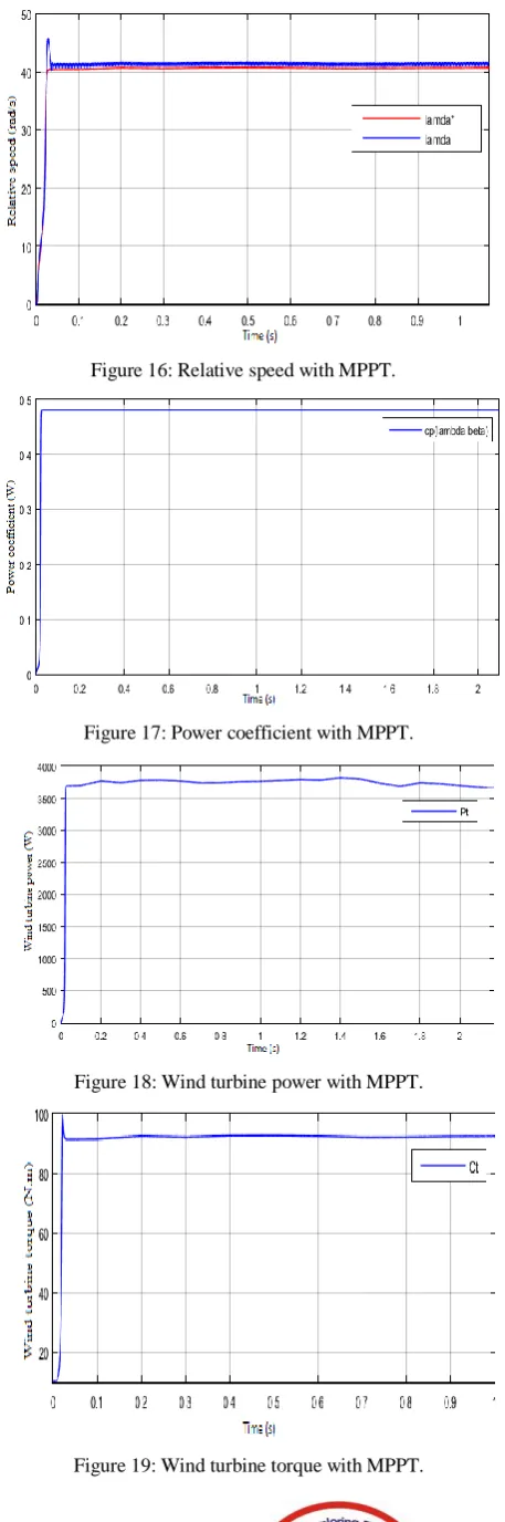
The MPPT control structure without speed control was simulated with a mean wind profile around 10m /s.
Figure 16: Relative speed with MPPT.
[image:5.595.79.296.319.479.2]Figure 17: Power coefficient with MPPT.
Figure 18: Wind turbine power with MPPT.
[image:5.595.78.298.531.699.2]MPPT and Pitch Angle Control of a Permanent Magnet Synchronous Generator based Wind Emulator
From the results Fig. 16, Fig. 17, Fig. 18 and Fig. 19, we see that the power, the aerodynamic torque and mechanical speed vary proportionally with the variation of the wind profile. Note also that the relative speed λ and the power coefficient Cp follow their references with a non-nule static error. This amounts to the absence of regulation of the speed of the turbine.
5. CONCLUSION
This paper discusses the modeling steps of a wind turbine to drive a DC machine to reproduce the torque and speed variations of the wind turbine. We first established a model to reproduce variations in wind speed. Torque and rotational speed are imposed as references to a DC machine. The MCC was modeled in turn and was controlled by a PI regulator for its simplicity and to reduce static error.
In a second step, by adapting the speed of the turbine to that of the wind one can extract the maximum power of the turbine using the technique MPPT. The simulation results show a good speed reference tracking of the optimal operating point.
As a perspective for the rest of this work,to model each component of the proposed systemto study the reactions of the permanent magnet synchronous generatorin the presence of network imbalance, voltage dips and fluctuations.
ACKNOWLEDGEMENT
This work has been supported by National Center for
Scientific and Technical Research (CNRST),
Rabat,Morocco.
REFERENCES
1. Colak, G. Fulli, S. Bayhan, S. Chondrogiannis and S. Demirbas, “Critical aspects of wind energy systems in smart grid applications,” Renewable and Sustainable Energy Reviews, vol. 52, pp. 155–171, December 2015.
2. X. Zhao and D. Luo, “Driving force of rising renewable energy in China: Environment, regulation and employment,” Renewable and Sustainable Energy Reviews, vol. 68, pp. 48-56, September 2016.
3. El Yaakoubi, A. Asselman, A. Djebli and E. H. Aroudam, “A MPPT strategy based on fuzzy control for a wind energy conversion system ,” 9th International Conference Interdisciplinarity in Engineering, INTER-ENG, vol. 22, pp. 697-704, Tirgu-Mures Romania, 8-9 October 2015.
4. R. Tiwari and N. R. Babu, “Fuzzy logic based MPPT for permanent magnet synchronous generator in wind energy conversion system,” IFAC, vol. 49, pp. 462-467, April 2016.
5. S. Chekkal, N. A. Lahaçani, D. Aouzellag and K. Ghedamsi, “Fuzzy logic control strategy of wind generator based on the dual-stator induction generator,” Electrical Power and Energy Systems, vol. 59, pp. 166-175, March 2014.
6. S. El Aimani. Modélisation de Différentes Technologies d’Eoliennes Intégrées dans un Réseau de Moyenne Tension ,Thèse présentée pour l’obtention du diplôme de Doctorat en Génie Electrique, Université des Sciences et Technologies de Lille. 2004.
7. Dahbi, N. Nait-Said, and M. S. Nait-Said, “A novel combined MPPT-pitch angle control for wide range variable speed wind turbine based on neural network,” International Journal of Hydrogen Energy, vol. 41, pp. 9427-9442, June 2016.
8. Mechter, K. Kemih, and M. Ghanes, “Sliding Mode Control of a Wind Turbine with Exponential Reaching Law,” Acta Polytechnica Hungaria, vol. 12, pp. 167-183, 2015.
9. AKEL Fethi, “ETUDE ET REALISATION D’UN EMULATEUR DE TURBINE EOLIENNE “, thèse de magister, école militaire polytechnique, Algerie 2009.
10. Nouira, and A. Khedher, “A contribution to the design and the installation of an universal platform of a wind emulator using a DC motor”, International Journal of Renewable Energy Research, vol. 2, pp. 797-804, October 2012.
11. M. Reddak, A. Berdai, A. Gourma, and A. Belfqih, “Integral backstepping control based maximum power point tracking strategy for wind turbine systems driven DFIG,” IEEE, 2nd International
Conference on Electrical and Information Technologies, pp. 888, 4-7 May 2016.
APPENDIX
TABLE 2:TURBINEAND MCC PARAMETERS.
Parameters of the Wind Turbine and MCC
PARAMETER VALUE PARAMETER VALUE
Nominal
power Turbine radius
Moment of
inertia
Armature
resistance
Coefficient of friction
Inductance of
armature
Moment of inertia
Constant torque