Abstract: A dual band low profile fractal antenna is proposed for Maritime Radio Navigation Services (MRNS). Minkowski fractal geometry is used on both the vertical boundaries of basic patch structure and by adjusting the fractal dimension desired operating frequency is achieved. The effect of antenna dimensions on the bandwidth is determined through the parametric analysis. Proposed antenna operates at 3 GHz and 9.4 GHz with a gain of 6.3 dB and 2.5 dB respectively. Furthermore, the resonating and radiation properties of the proposed antenna are measured experimentally. Measured results of the proposed antenna are highly convincing and in good agreement with simulated results.
Keyword: Minkowski Fractal, Bandwidth, Multiband, Maritime Radio Navigation, Gain.
I. INTRODUCTION
Navigation is the activity of controlling the motion of objects by exactly knowing its position. MRNS is one of the navigation services that is used for the safe operation of ships[1]. MRNS operate in many different frequency bands, in different regions of the world according to ITU specified frequency bands. Some of the specified frequency bands for MRNS are 2900-3100, 5470-5650, 8850-9000 and 9200-9500 MHz. Such kind of communication needs high efficient, multifunctional, and low profile systems. Advancement of such systems depends on the functioning and working of antenna used in the system. Conventional antennas work for single frequency band which leads to an increase in a number of onboard antennas. To reduce the number of antennas, multiband and multifunctional antennas are needed for such kind of communication systems. Microstrip patch antenna with fractal shaped structure is a decent answer to the requirements like small size, low cost, multiband, wideband and application-specificity[2][3]. Fractal is a set of curves or surfaces which have larger Hausdorff Besicovitch dimension than the topological dimension[4]. Incorporation of fractal geometry in patch structure makes it multiband antenna. In the past few years, the use of fractal geometry in the design of the antenna is increased and still, fractals are very popular among antenna engineers because of its phenomenal capabilities. The principle points of interest of fractal antenna over regular antenna are its multiband operation and diminished size [5-9]. The fractal antenna has valuable applications in various kinds of communications. M. Comisso in [10] reported the resonant behavior of Minkowski fractal and its capabilities of
Revised Manuscript Received on September 03, 2019
* Correspondence Author
Ashwini Kumar*, Department of Electronics and Communication Engineering, Sant Longowal Institute of Engineering and Technology, Longowal, Sangrur, Punjab, India,
Amar Partap Singh Pharwaha, Department of Electronics and Communication Engineering, Sant Longowal Institute of Engineering and Technology, Longowal, Sangrur, Punjab, India,
size diminishing. There are a few different strategies reported in [11] [12] to diminish the measure of the microstrip patch antenna, for example, shorting pins, presenting of U-openings, utilizing of high permittivity substrates and fractal geometrical structure. A modified Minkowski rhombic patch fractal antenna is proposed in [13] which has multiband performance and can be used for different wireless applications. However, the size of the antenna is large. In [14] ultra-wideband antenna is reported using Minkowski fractal structure. Fractal structure generates multiple resonances which are used to achieve wideband characteristics. Antenna using different fractal geometries are proposed in [15][16]17] with multiband characteristics which can be used for radio navigation as well as different satellite services in different frequency band. A microstrip patch antenna with the slot is reported in [18] for RADAR, WLAN, fixed satellite services and maritime mobile services. Proposed antenna covers 2-6 GHz frequency range. A microstrip patch antenna working at two frequencies is reported in [19]. Proposed antenna operates at 2.7GHz and 4.57GHz with a peak gain of 1.6dB and 4.9dB respectively. The proposed antenna can be used for fixed satellite, astronomy, aviation and for space research. In [20] fractal antenna array has been designed for MRNS and satellite services which has a tri-band performance with highly convincing results. The antenna element used in the array is optimized using dragonfly optimization. A multiband fractal antenna with large structure has been analyzed in [21] which covers MRNS in S-band and X-band. In [22] a quad-band antenna is reported using Sierpinski fractal operating at 2.12 GHz, 6.6 GHz, 9.33GHz and 13.25 GHz frequencies which has a possible use for different satellite and radio navigation applications. Thus from the literature it is perceptible that there is still a huge possibility of development of dedicated miniaturized multiband antenna using fractal geometry. Therefore, this report intends to provide a straightforward solution to the compact multiband antenna. The proposed antenna has been designed on Roger substrate using simple and easy to fabricate geometrical structure. The most appealing feature of the proposed compact fractal antenna is that it operates specifically only for MRNS at two frequency bands (2900-3100 MHz and 9200-9500 MHz) in S-band and X-band with good resonance and radiation characteristics. Organization of the remaining part of the paper is as follow: Section 2 describes the design and structure of the proposed antenna. Section 3 shows the results and discussion for the simulated and fabricated antenna. Section 4 gives the conclusion.
Dual Band Minkowski Fractal Antenna for
Maritime Radio Navigation Services
II. ANTENNADESIGN
Rogers RT/duroid 5880(tm)dielectric material having a size of 50.9 mm × 49.9 mm×1.5 mm, a loss tangent of 0.0009 and dielectric constant of 2.2 has been used as substrate for proposed antenna. The dielectric material Rogers RT/duroid 5880(tm) provides high gain and high accuracy in results due to low dielectric constant value [2]. In this work Minkowski fractal geometry is used to change simple patch into a fractal structure, this particular geometry is selected because of its simple and easy to integrate characteristics, another technicality that is observed during analysis is that its dimensions directly affects the resonating frequencies which help in achieving the desired response. Hermann Minkowski introduced first time Minkowski fractals in the year 1885. In this work the two sides of square patch are replaced by Minkowski curve, one begins with the straight line of a unit length called the initiator, than by taking three equal parts of length (1/3) and by replacing middle part with two vertical segment (A) and one horizontal segment (B) of equal length this procedure is repeated to generate fractal geometry as shown in Figure 1. In the reported work, length of the vertical segment (A) is varied in comparison of the horizontal segment (B). This variation provides a design flexibility to modify aspect ratio (ɳ) of the generator. The patch edges are modified according to Minkowski fractal, in the first iteration as represented A1 and B1; similarly to make the second iteration again edges are modified as A2 and B2. Here the ratio of the A and B factor represents the aspect ratio(ɳ) which is optimized using parametric optimization in HFSS environment and final value for aspect ratio are selected as ɳ1 is equals to 49% and ɳ2 is equals to 19% as given in Eq. (1) and Eq. (2) where the best results are achieved. Basic initiator for the Minkowski fractal and further transformation is shown in Figure 1. Figure 2 shows the basic patch antenna to final transformed Minkowski fractal antenna with modified ground width. Basic patch shown in Figure 2(a) has a dimension of 32.9mm ×32.9mm and dimension of the ground is 50.9mm × 6.6mm. Proposed antenna is fed with an inset feed structure having a dimension of 17.3mm × 1.1mm. Table I shows the all dimensional details of the proposed fractal antenna. The inset feed is used because it provide advantages of both coaxial feed and microstrip line feed simultaneously because it can be connected at the appropriate impedance point and provide the ability to place feeding circuitry near the elements on the same substrate and avoid a multilayer board. Figure 2(b) and Figure 2(c) shows the first and second iteration of the proposed fractal antenna.
ɳ
(1)
ɳ
[image:2.595.308.495.51.188.2]
(2)
Fig. 1. Basic operator and further transformation for Minkowski fractal
[image:2.595.311.541.307.443.2]In Figure 2(d) final proposed fractal antenna with optimized ground width is shown. It has been noticed in simulation results that there is a significant variation in the bandwidth of proposed antenna with the change in width of ground which can be observed from the data tabulated in table III.
Table-1: Different dimension of proposed antenna
Parameter Value (mm)
Length of substrate 49.9
Width of substrate 50.9
Height of substrate 1.5
Length of patch 32.9
Width of patch 32.9
Length of feed 17.3
Width of feed 1.1
Length of ground 6.6
Width of ground 28.9
A1 5.4
B1 10.96
A2 0.7
B2 3.66
A. Effect of aspect ratio (ɳ) on the resonance frequency of the antennaSubmission of the paper
[image:2.595.44.549.611.786.2]A critical analysis is done to relate the aspect ratio (ɳ) of Minkowski Fractal geometry and resonance frequency of the proposed antenna. Various dimensions of Minkowski fractal antenna has been parametrically analyzed using HFSS simulation tool to find the optimum solution. Table II shows the performance parameter for the different values of ɳ at different stages of design. It has been observed in the simulation results that ɳ affects the resonant frequency and bandwidth of the antenna significantly as shown in table II. ɳ is varied for both of the iterations, for first iteration ɳ1 is varied from a value of 38% to 60% and after observing the
(c) 2nd iteration (d) 2nd iteration with modified ground width Table-II: Parametric study of aspect ratio at
first and second iteration
Iteration ɳ% Resonant frequency (GHz)
Bandwidth (MHz)
First
ɳ1%=38 3.0, 9.8 117, 500
ɳ1%=44 3.0, 9.7 126, 400
ɳ1%=49 3.0, 9.5 95, 284
ɳ1%=55 3.0, 9.4 67, 288
ɳ1%=60 3.0, 9.1 93, 160
Second
ɳ2%=11 3.0, 9.6 120, 680
ɳ2%=19 3.0, 9.4 121, 720
ɳ2%=35 3.0, 9.3 131, 250
ɳ2%=49 3.0, 9.2 118, 205
ɳ2%=65 9.1 120
results for the targeted application the best value for ɳ1 that is 49% is selected, similarly ɳ2 is varied from value of 11% to 65% and best value for ɳ2 is selected as 19% where the proposed antenna provides the best results in terms of resonant frequency and bandwidth for desired application.
B. Effect of ground width on the bandwidth of the antenna
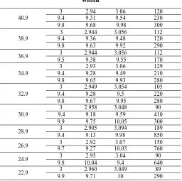
When the width of the ground is varied, it has been observed that there is a significant impact on the bandwidth of the antenna. To study the effect of ground width on bandwidth and to find optimum bandwidth a parametric analysis is done for the ground width. The ground width is varied from 22.9 mm to 50.9 mm and at each variation, the effect on bandwidth is observed. Optimum result in terms of bandwidth at desired frequencies is found at a ground width of 28.9 mm. Table III shows the effect of ground width variation on antenna’s bandwidth. The final design of antenna resonates at 3.0 GHz and 9.4 GHz with a bandwidth of 189 MHz and 850 MHz respectively.
C. Analysis with different substrate
[image:3.595.55.259.93.240.2]The proposed antenna is analyzed with different substrate materials. For the analysis of proposed fractal antenna four substrates are taken Rogers RT/duroid 5880(tm) (Єr= 2.2), Roger TMM3 (Єr= 3.27), FR4 (Єr= 4.4) and Rogers RT/duroid 6006 (tm) (Єr= 6.15). The resonant behavior of fractal antenna with different substrate is shown in table IV. It has been noticed that the lower resonating band shift to higher resonating frequency when the dielectric constant is increased as well as the bandwidth is also reduced for upper resonating band. Desired results for targeted application of MRNS is achievable using the Rogers RT/duroid 5880(tm) (Єr= 2.2) only as it provide resonance at 3 GHz and 9.4 GHz with a bandwidth of 189 MHz and 850 MHz respectively. Gain for the targeted frequency bands is 6.3 dB and 2.5 dB which are also good.
Table-III: Variation in bandwidth with ground width
Ground width (mm) fr (GHz) fl (GHz) fh (GHz) Bandwidth (MHz)
50.9 3 2.94 3.06 121
9.4, 9.8 9.23 9.95 720
48.9 3 2.94 3.05 106
9.4, 9.9 9.25 9.925 675
46.9 3 2.95 3.05 98
9.4, 9.8 9.303 9.985 682
44.9 3 2.94 3.06 120
9.4, 9.8 9.31 9.94 630
42.9 3 2.95 3.052 102
9.4, 9.9 9.31 9.99 680
40.9
3 2.94 3.06 120
9.4 9.31 9.54 230
9.8 9.68 9.98 300
38.9
3 2.944 3.056 112
9.4 9.36 9.48 120
9.8 9.63 9.92 290
36.9 3 2.944 3.056 112
9.5 9.38 9.55 170
34.9
3 2.93 3.06 129
9.4 9.28 9.49 210
9.8 9.65 9.93 280
32.9
3 2.949 3.054 105
9.4 9.28 9.5 220
9.8 9.67 9.95 280
30.9
3 2.958 3.048 90
9.4 9.18 9.59 410
9.9 9.75 10.05 300
28.9 3 2.905 3.094 189
9.4 9.13 9.98 850
26.9 3 2.92 3.07 150
9.7 9.27 10.03 760
24.9 3 2.95 3.04 90
9.8 10.04 9.4 640
22.9 3 2.960 3.049 89
9.9 9.71 10 290
Table-IV: Analysis of proposed antenna with different substrate Dielect ric Const ant Loss tang ent Resona nt frequen cies (GHz) Reflect ion coeffici ent (-ve) Bandwi dth (MHz) Input Impeda nce (Ohms) Ga in (d B)
2.2 0.00
09
3.0 19.3 189 106.9 6.3
9.4 24.2 850 91.7 2.5
3.27 0.002 7.9 19.2 461 71.2 1.8
9.45 22.8 373 79.2 8
4.4 0.02
7.025 31.8 490 71.7 0.0
6
8.2 24.3 250 74.4 3.5
6.15 0.001
9
5.775 12.9 42 89.5 1.1
6.15 18.5 104 48.5 2.3
6.975 13.5 95 49.7 6.9
8.025 13.1 51 122.7 0.2
8.825 16.8 125 111.9 7.6
III. RESULTANDDISCUSSION
[image:3.595.41.296.672.791.2]for measurement of radiation characteristics in anechoic chamber. In figure 5 simulated as well as measured reflection coefficients are shown for the proposed antenna.
[image:4.595.53.283.89.208.2]Fig. 3. Reflection coefficient of all iteration of proposed antenna
Fig. 4. Proposed antenna (a) In the anechoic chamber (b) Connected to VNA
[image:4.595.306.566.130.267.2]Fig. 5. Simulated and the Measured Reflection coefficient of the proposed antenna
Table-V:Performance parameter of proposed fractal antenna
Number of Iteration
Resonant frequencies
(GHz)
Reflection coefficient
(-ve)
Bandwidth (MHz)
0th 2.9 13.6 81
8.3 11.8 155
1st 3.0 15.2 95
9.5 14.9 284
2nd 3.0 18.7 121
9.4 17.5 720
Proposed antenna
3.0 19.3 189
9.4 24.2 850
Measured result
3.12 15.3 260
9.29 22.9 480
Measured results are tabulated in table V and as expected, the measured Reflection coefficient is in good agreement with the simulated Reflection coefficient values except a small deviation which may be due to scattering from surrounding area, copper loss, and soldering bumps. Current distribution plot of the designed antenna is demonstrated in Figure 6 for the two resonating frequencies. Figure 6(a) represents the current distribution at 3.0 GHz and Figure 6(b) at 9.4 GHz. In
Figure 6(a) it has been noticed that the current is almost zero near to the edges and maximum current density is at the center of the antenna which signifies a strong radiation at 3 GHz and similarly in Figure 6(b) the maximum current density is noticed in the fractal area of the antenna which produce a strong radiation at the 9.4 GHz.
[image:4.595.321.530.299.729.2]Fig. 6. Current Distributions at (a) 3GHz (b) 9.4GHz
[image:4.595.53.282.367.501.2] [image:4.595.48.289.561.692.2]Fig. 8. Gain v/s Frequency plot of proposed antenna
Radiation properties of the antenna have been shown in the form of 2-D radiation pattern. It is a two-dimensional representation of radiated energy from the antenna in E-plane (YZ-plane) and H-plane (XZ-plane) which describe the antenna’s radiation performance. Simulated and measured radiation pattern for the proposed antenna at 3.0 GHz and 9.4GHz is shown in Figure 7. It has been noticed that simulated and measured radiation pattern in both the XZ-plane and YZ-plane are in good agreement with each other. In XZ-place radiation patterns are nearly Omni-directional. Figure 8 shows the simulated gain plot for the proposed fractal antenna. The simulated gain for the proposed antenna at two resonating frequencies is 6.3 dB and 2.5 dB at 3 GHz and 9.4 GHz respectively. From the gain versus frequency plot it can be noticed that at 3 GHz the proposed antenna has high gain and for 9.4 GHz the gain value is moderate which signify good radiation property of the antenna.
IV. CONCLUSION
This paper presents a dual band inset fed Minkowski fractal antenna. The proposed antenna is tuned at a desired frequency by adjusting the aspect ratio of Minkowski fractal geometry. Ground width is parametrically optimized to find optimum bandwidth in desired bands. The antenna is optimized to resonate at 3.0 GHz (2.905 GHz to 3.094 GHz) and 9.4GHz (9.13 GHz to 9.98 GHz) with an impedance bandwidth covering frequency bands for maritime radio navigation services. The designed antenna has nearly omnidirectional radiation pattern, and it has high gain of 6.3 dB at 3.0 GHz and a moderate gain of 2.5 dB at 9.4 GHz. Resonating and radiation characteristics of the proposed fractal antenna have been measured which are highly convincing.
ACKNOWLEDGMENT
To provide the outstanding lab facilities, authors would like to thank the Department of Electronics and Communication Engineering of Sant Longowal Institute of Engineering and Technology (Deemed-University), Longowal, Sangrur, Punjab, India and CARE Lab, IIT Delhi, India.
REFERENCES
1. C. Specht, A. Weintrit, and M. Specht, “A history of maritime
radio-navigation positioning systems used in Poland,” J. Navig., 2016.
2. C. Balanis, Antenna Theory - Analysis and Design. 1997.
3. R. Garg, P. Bhartia, I. Bahl, and A. Ittipiboon, Microstrip antenna
design handbook. 2001.
4. B. B. Mandelbrot, The fractal geometry of nature, vol. 8, no. 4. 1982.
5. D. H. Werner, R. L. Haupt, and P. L. Werner, “Fractal antenna
engineering: the theory and design of fractal antenna arrays,” IEEE Antennas Propag. Mag., vol. 41, no. 5, pp. 37–59, 1999.
6. D. H. Werner and S. Ganguly, “An overview of fractal antenna
engineering research,” IEEE Antennas Propag. Mag., vol. 45, no. 1, pp. 38–57, 2003.
7. F. Wang, F. Bin, Q. Sun, J. Fan, F. Liang, and X. Xiao, “A novel UHF
Minkowski fractal antenna for partial discharge detection,” Microw. Opt. Technol. Lett., vol. 59, no. 8, pp. 1812–1819, 2017.
8. G. Singh and A. P. Singh, “On the design of planar antenna using Fibonacci word fractal geometry in support of public safety,” Int. J. RF Microw. Comput. Eng., vol. 29, no.2, p. 1-7, 2019.
9. A. Kumar and A. P. Singh, “Design of micro-machined modified
Sierpinski gasket fractal antenna for satellite communications,” Int. J. RF Microw. Comput. Eng., vol. 29, no. 9 p. 1-10, 2019.
10.M. Comisso, “Theoretical and numerical analysis of the resonant
behaviour of the Minkowski fractal dipole antenna,” IET Microwaves, Antennas Propag., vol. 3, no. 3, p. 456, 2009.
11.S. R. Best, “On the performance properties of the Koch fractal and other bent wire monopoles,” IEEE Trans. Antennas Propag., vol. 51, no. 6, pp. 1292–1300, 2003.
12.C. P. Baliarda, J. Romeu, and A. Cardama, “The Koch monopole: A
small fractal antenna,” IEEE Trans. Antennas Propag., vol. 48, no. 11, pp. 1773–1781, 2000.
13.C. Mahatthanajatuphat, S. Saleekaw, P. Akkaraekthalin, and M.
Krairiksh, “a Rhombic Patch Monopole Antenna With Modified Minkowski Fractal Geometry for Umts, Wlan, and Mobile Wimax Application,” Prog. Electromagn. Res., 2009.
14.S. Tripathi, A. Mohan, and S. Yadav, “Ultra-wideband antenna using
Minkowski-like fractal geometry,” Microw. Opt. Technol. Lett., 2014.
15.Ashwini Kumar and Amar Partap Singh Pharwaha, “Triple Band
Fractal Antenna for Radio Navigation and Fixed Satellite Services using Dragonfly Optimization,” Adv. Electromagn., vol. 8, no. 3, pp. 43–49, 2019.
16.A. Kumar and A. P. Singh Pharwaha, “On the Design of Wideband
Sierpinski Carpet Fractal Antenna for Radio Navigation and Fixed Satellite Services,” in 2019 6th International Conference on Signal Processing and Integrated Networks (SPIN), 2019, pp. 736–738.
17.Sachin Chauhan, J. K. Deegwal, and R. Gera, “A Design of Triangular
Sierpinski Gasket Fractal Antenna,” Int. J. Electron. Commun. Technol., vol. 4, pp. 62–64, 2013.
18.P. A. Ambresh, P. M. Hadalgi, and P. V. Hunagund, “Planar microstrip
slot antenna for S & C band wireless applications,” in Journal of Physics: Conference Series, 2013, vol. 435, no. 1.
19.Deepanshu Kaushal and T. Shanmuganatham, “Danger Microstrip
Patch Antenna for Fixed Satellite Applications,” in IEEE International Conference on Emerging Technological Trends [ICETT], 2016, pp. 1–6.
20.A. Kumar and A. Partap, “On the Design of 2×2 Element Fractal
Antenna Array using Dragonfly Optimization,” Int. J. Comput. Appl., vol. 179, no. 33, pp. 27–34, Apr. 2018.
21.P. Dalsania, B. Shah, T. Upadhyaya, and V. V. Dwivedi, “Analysis of
multiband behaviour on square patch fractal antenna,” in Proceedings - International Conference on Communication Systems and Network Technologies, CSNT 2012, 2012, pp. 76–78.
22.M. Ram, S. Das, and R. L. Yadava, “A Quad Band Sierpinski
Trapezoidal Fractal Patch Antenna for Wireless Applications,” J. Microwaves, Optoelectron. Electromagn. Appl., vol. 16, pp. 25–37, 2017.
AUTHORS PROFILE
Dr. Amar Partap Singh Pharwahawas born in Sangrur,Punjab in 1967 and received his BTech degree in ECE from GNDU, Amritsar in 1990. He received his MTech degree from REC, Kurukshetra in 1994 and PhD degree in 2005. Presently, he is a professor of ECE as well as part-time chief vigilance officer (appointed by the Govt. of India) at SLIET, Longowal. Dr Singh is credited with a professional experience of more than 24 years. He has guided seven PhD thesis. He has published more than 180 research papers in various national and international journals/conferences and received various awards including IETE Students Journal Award-2006 by IETE, New Delhi, Certificate of Merit in 2006, KF Antia Award in 2009, Sir Thomas Ward for the year 2010, and again KF Antia Award in 2014 by the Institution of Engineers (India).