Rochester Institute of Technology
RIT Scholar Works
Theses Thesis/Dissertation Collections
1987
Animator: an object-oriented approach
Stephen Kurtz
Follow this and additional works at:http://scholarworks.rit.edu/theses
This Thesis is brought to you for free and open access by the Thesis/Dissertation Collections at RIT Scholar Works. It has been accepted for inclusion in Theses by an authorized administrator of RIT Scholar Works. For more information, please [email protected].
Recommended Citation
Rochester Institute of Technology School of Computer Science and Technology
Animator
An Object-Oriented Approach to the
Creation and Direction of Computer Animated Actors by
Stephen Kurtz
A thesis,submitted to
The Faculty of the School of Computer Science and Technology,
inpanial fulfillment of the requirements for the degree of Master of Sciencein Computer Science
Approved by:
A thesis,submitted to
The Faculty of the School of Computer Science and Technology,
Title of Thesis: Animator: An Object-Oriented Approach to the Creation and Direction of Computer Animated Actors.
I hereby grant permission to the Wallace Memorial Library of RIT, to reproduce this thesis in whole or in part. Any reproduction will not be for commercial use or profit.
1. Preliminary Information
1.1. Abstract
Object-oriented programming is presented as a paradigm for developing interactive systems for computer animation. Object types, evolved conceptually from graphics turtles, are implemented to provide the animator with familiar metaphors for the specification of motion in three-dimensional space. The intention is to create objects that can represent actors, cameras, and decor that the user can direct and animate in a relatively intuitive manner. Vector and turtle objects support the actors, which respond to messages to orient, accelerate and draw themselves on the screen. The MacApp object libraries are used to implement the standard Macintosh user interface and a unit is developed which implements vectors, actors and three-dimensional graphics turtles as objects. The object-oriented approach encourages a conceptual consistency in the external and internal interfaces and is intended to facilitate the development of extensible characters and tools through the cooperative efforts of animators and programmers.
1.2. Key Words and Phrases
1.3. TableofContents
1. Preliminary Informatioa 2
1.1 Abstract 2
1.2 Key WordsandPhrases 2
1.3 TableofContents 3
2. Proposal 7
3. IntroductionandBackground 9
3.1 Computer Animation 9
3.2 Object-OrientedProgrammingSystems(OOPS) 9
3.3 Actor BasedSystemsandtheLogoTurtle 10
3.4 Animator 11
4. Vectors 12
4.1 TVectorObject Type 12
4.2 Thedatafields 12
4.3 Methods for assigningvalues. 12
4.4 A geometricinterpretation 13
4.5 Vectorcoordinates 14
4.6 The geometryof vector addition 14
4.7 Thecomponents fX,fY andfZ 15
4.8 Theimplementationof vectoraddition 15
4.9 The implementationofthe scalarproduct 16
4.11 Thedotproduct 17
4.12 ImplementationoftheTVectorObject Type 18
5. Local Coordinate Systems andtheTLCS ObjectType 20
5.1 The TLCS Object Type 20
5.2 fYaw,fPitchandfRoll 21
5.3 fLensandfitsView 21
5.4 Allocation and assignment 22
5.5 Deepand shallow methods 22
5.6 Methodsofrotation 22
5.7 TheTiltUp method. 23
5.8 Moving 23
5.9 ImplementationofTLCS Object Type 24
6. The Turtle: aVector-BasedGraphics Pen 29
6.1 Turtlegraphics 29
6.2 Drawingan actor 30
6.3 TTurtleobjecttype- datafields 30
6.4 Projectionontotheplane 31
6.5 The geometry ofTTurtle. Project 31
6.6 Perspectiveprojection 32
6.7 Drawingwith the turtle 32
6.8 Overridinginheritedmethods 33
7. Actors: aTemplate for PicturesthatMove 39
7.1 An animatedobjecttype 39
7.2 TActordata fields 40
7.3 UpdatingthePolygon 40
7.4 Overriding DrawPoly 41
7.5 Movingthepicture 41
7.6 Navigation in 3-D space 42
7.7 DescendantsofTActor 43
7.8 Commandsastext 44
7.9 Implementation ofTActorObject Type 45
8. Animator: a stageforthe actors 54
8.1 Thestagefortheactors 54
8.2 Initializingactors thecast 54
8.3 Drawingtheview 55
8.4 Selectingobjects - mousecommands 55
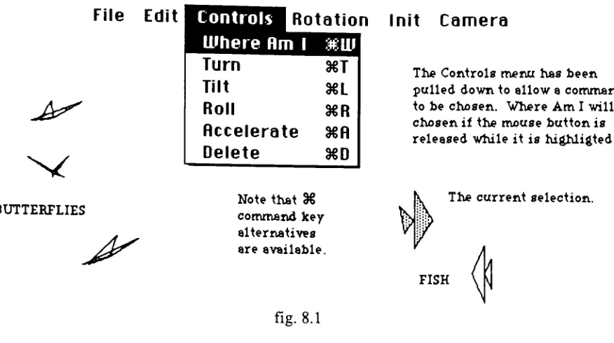
8.5 Thecontrols menu 56
8.6 Simulating themove 56
9. Conclusions 57
9.3 Lessons Learned 57
9.2 Future ExtensionsofAnimator'sObject Types 57
9.3 Extensions to theSystem 58
10. Appendix: ObjectPascal 59
10.2 Methodsor messages 59
10.3 Inheritance. 60
10.4 Instancesof an objecttype 60
10.5 MacAppunits 61
10.6 TApplicationandTDocument 61
10.7 TFrameandTWindow 62
10.8 TView 62
10.9 TCommand 63
2. Proposal
Althoughthe real-time creation anddisplay ofanimated sequences in three-dimensional
space remains a problem forthe future, a greatdeal has been done to assist the animator in creating animated films frame by frame. Currently, computers are used in the
interactive creation ofobjects,the generation ofsuccessiveimages to simulate motion or
othertransformations, andthe control ofhardware inthe production andpost-production
stages ofmaking afilmor video. Thisthesis willfocus on the problems surrounding the
specification of motionby theanimator.
Many animators are interested in using the computer as a tool, but few are prepared to become programmers in the process. The resistance to the mathematical modeling of
objects and motion is in part due to the nature of the work involved, but of equal importance for many animators is the conviction that traditional animation owes its
appeal not to the accuracy with which it portrays the physical world, but rather to the
expressiveness ofthe artist/animator. The goal for many is not to simulate the laws of
motion butratherto simulate traditional animation. User-orientedpaintsystemsdonot as
yet provide the animator with the tools to describe satisfying movement in a
three-dimensionalspace.
Iamparticularly interested inworkingtowardaninteractive environmentfortheanimator
that is conceptually compatible with an extensible object-oriented programming language. The system would be modal, providing separate environments for creating
differentclasses ofobjects along with the methods that class of objects might support.
My intention is to give the animatordirectcontrol ofthe scene whenever possible, while
offering theextensibilityofaprogramminglanguage in othermodes. Forexample,a new
classof objects might becreatedin one mode, while a new actor orinstance ofthatclass
might be described in a second mode, anda script created for that actor in athird. The
modificationor creation ofthenew classmight require theuse ofa computerlanguage by the animatoror aprogramming co-worker, while the other tasks might be accomplished moredirectly.
I hope to implementa systemin order toexplore methods ofcreating objects with parts
that move relative to a local co-ordinate system while the entire object accelerates or
Iwouldliketogive the animatortheabilitytosimulate cameramovements and perhaps a
variablelight source. Theemphasis willbe onprovidingan intuitiveinterface anduseful feedbackforbothprogrammed andinteractivework.
I intend to use a version of Pascal with support for object-oriented programming. My
current thought is that objects which can behave like three-dimensional graphics turtles
canbecomeactors in an animation script. I hopetoallow the animatortoexpress changes
in position and rates of change relativeto feedback about current position, heading and
velocity, rather than relating these changes to a global coordinate system. To my
knowledge,thisis anovel approachto the specificationof motion.
I would like to acknowledge my debt to Nadia and DanielThalmann, for the guidance and direction supplied by theirbook, ComputerAnimation, Theory and Practice [Thai
1985] and to Harold Ableson and Andrea diSessa, for their extraordinary text, Turtle
3. Introduction and Background
3.1. Computer Animation
The creation of animated pictures is a complex andlabor intensiveprocess in which the
computer can play manyroles. Subsequently the term "computer
animation" is not well
defined. Computers are usedinthecreationofdrawings, the simulationofmovement and
in various stages of the production and editing process. Although the real-time
computation and display of animated graphics is now possibile for simpler images, the emphasis here is on the use ofcomputers to animate complex three-dimensional scenes
thatrequire a frame-by-frameapproach.
Systemsthat aidin the drawing stagevary from paint systemsthat assistthe artistin the
creation of an image on the screen, to modeling systems which can represent
three-dimensional solids as stored data and render stored objects to reflectdifferent points of
view, lightingand surface attributes. They alsodiffer markedly in the skills they require of the user, which may vary from studio drawing ability to advanced programming
techniques. Different parts of the process are often handled by different systems and
assigned todifferentmembersofaproduction team.
In the creation of motion the computeris often usedfor in-betweening. In this process
the animatorcreates a setofdrawingscalledkeyframes, whichdepictan object at various stages during an animated sequence, and the computer creates the drawings that are
required in-between the keyframes. These systems are modeled after adivision oflabor
thatwas often usedin hand animation. Other systems can generate the framesrequired
to show an image moving along apath described by the animator. Modeled animation
systems often allow three-dimensional movements to be programmed by the animator,
and then create therequired sequence offrames from the storedinformation. Real-time
playback of animated sequences is not yet possible for realistic three-dimensional
animation,but many systems now offer real-timepreviewing orfeedbackwith simplified
(wireframe) images.
Computer animators are involved in the modeling of complex objects and the
specification of their behavior. Recent work on data abstraction [Guttag 77] has had important implications for computer animation [Thai 83]. Many of the objects modeled
by animators (i.e. actors, props, cameras, lights, backgrounds) are specific examples of
classes of conceptually similar objects which interact with each other in a prescribed
manner to create the scenes recorded on film. Object-oriented programming systems
such as SMALLTALK [Gold 84] offer tools extraordinarily well suited to the graphics programmer.
SMALLTALK defines objects as entities consisting of private memory and a set of
operations which communicate by sending messages. Each object is an instance of an
abstract data type (class), binding adata structure with a setofoperations (responses to
messages) that constitute the only access to that data. Classes of objects can be
customized by defining new classes whichrefine and extend the inherited interface and
data structureoftheirdeclaredancestors.
The three concepts that characterize OOPS are: objects, messages and inheritance. Object-oriented programming encourages a design strategy that organizes programs
around a hierarchy of abstract data types, rather than the refinement of procedural objectives. An object-oriented system evolves as a collection ofobjects, customized and
refined by descendants, interacting by message sending. A version ofPascal [Appl 87]
supporting these conceptswas usedtocreatethe graphicsobjectsin Animator.
3.3. Actor Based Systemsand theLogo Turtle
The term
"actor"
[Hewitt 73] describes an object that can send and receive messages.
Hewitt describes a system in which all elements are actors and the only activity is
messages sent between them. Programming in this system consists of defining the
responses made bydifferentclasses ofactorstoreceivedmessages.
Kenneth Kahn created a system called DIRECTOR [Kahn 76] based on an actor that
could be
"asked"
to do all the things a LOGO turtle can do. LOGO [Papert 70] is a
language developed at M.I.T. for use with children. The LOGO turtle responds to the
withproceduraldefinitions. Kahn animated scenesby synchronizingresponsesto aclock
with control structureslike AFTER2 MORE TICKS.
Reynolds created the Actor/Scriptor Animation System (ASAS) at the Architecture Machine Group atM.I.T. [Reynolds 82]. ASAS messages are lisp-like functions which
rotate an actor's local three-dimensional coordinate system. These messages extend the
LOGO turtle's LEFT andRIGHT commands toinclude UP, DOWN, CLOCKWISE and COUNTER CLOCKWISE, so that his actors can be animated in three-dimensions. Reynoldsdescribeshis"actor"
as a "chunk" ofcodethatisexecutedonce eachframe.
Also at M.I.T, Abelson and diSessa described a similar three-dimensional turtle in their
text, Turtle Geometry [Abel 81]. It was Abelson's description of a three-dimensional turtle and my experiences helping students learn to program with turtle graphics, that
inspired Animator.
3.4. Animator
Animator's actors are a class of objects, with private information, that respond to
messages and are refined through inheritance very much like the SMALLTALK objects described in section 3.2 above. They were developed before I learned about Hewitt's
actors, and should not be confused with them. Animator's actors were designed to be animated or scripted interactively and easily extended through inheritance by a
programmer. All actors, graphicsturtles, and cameras descend from a common ancestor from which they inherittheirgeneral abilitiesto respondto messages to orient and move in space.
Their inherited data structures includealocal coordinate system based on vector objects
4. Vectors
4.1. Vectors: TVector Object Type
The TVector type implements the fundamental vector methods on which all of the
graphics objectsin Animator are based. The definition ofvectors as an object type is
more for the purpose of data abstraction than inheritance (the object type is itself childless),butalldescendantsoftheTLCS (localcoordinatesystem) typeinherit TVector
data fields. The descendants of TLCS include all of Animator's actors, turtles and cameras.
Thevectorrepresentationofsuch quantities asposition, distance,orientation,velocityand
acceleration,is geometrically intuitiveandanalyticallypowerful. The fundamental vector
methodsdescribed in this section supportthedrawing, moving and projection techniques used to specify and simulate motion in Animator. Where appropriate, a geometric
interpretation willbeoffered. An Object Pascal [Appl 87] implementationoftheTVector
typeis includedat the endofthis section.
4.2. Vectors: thedatafields
A vector in three-dimensional space is an ordered triple of real numbers. They are represented by threedatafields, fX,fY andfZ in theTVectorobjecttype. Early versions
ofAnimatorused MPW Pascal'sFDCED type, which represents areal numberin 4bytes,
using the first two bytes for the integer and thelast two for the fractional part of a real
number. Precision is adequate and storage is half that of the Pascal REAL type. Arithmetic withnegativevalues was cumbersome and assignment was inconvenient. As
Animatorevolved,computational speed proved morevaluable thanstorage space,andthe
current version benefits in this regard from using the MPW EXTENDED type to
represent all real values. This 10 byte representation was chosen, not for the added
precision,but because all representations of real numbersin theStandard Apple Numeric Environmentare convertedto this typebeforecomputation. [Appl 85]
Vectors are represented as objects rather than as Pascal records to provide data
encapsulation. Although Object Pascalpermitsdatafieldsto bereferencedandmodified
much as a programmer might assign a value toa fieldof a Pascal record, this is avoided
inAnimator. Vector data fieldsare alteredonly by callingthe methodsdefined as partof
the TVectorobject type. In this respect,TVector is atemplate foran abstract datatype.
Direct references to an object's data fields, which take the form aVector.fX, should be
thoughtofasfunction callsthatreturnthevalue ofthereferenced field.
An instance variable oftype TVector is morelike aPascalpointer(it is actually ahandle
ordoublepointer) thanaPascal record. The NEW statement allocates spaceforthe data
fields andthe shallow Freemethod,which allobjectsinherit fromTObject, issufficientto
deallocate ordisposeofthe allocated memory. Forthe sake ofthefollowing discussion, assume that firstVector and secondVector are instance variables of type TVector for
whichmemory has been allocated. Then thestatements or messages:
firstVector.Init(20, 22.5, 25);
secondVector.CopyOf(firstVector);
wouldinitialize theobjectfirstVectorto the triple <20, 22.5,25>andmake secondVector
a copy of firstVector. Init and CopyOf are methods of the TVector object type, or
messages that allobjectsofthis type respondto. Thesemethods are defined like Pascal
procedures, but called in the style of a Pascal recordreference, as above. It should be
noted that thestatement:
secondVector : = firstVector;
would make secondVector a second pointer to the object already pointed to by
firstVector,ratherthan a separatecopy.
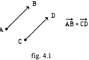
4.4. Vectors: ageometric interpretation
When interpreted as a directed line segment, vectors can be used todescribe quantities
that have both magnitude and direction, such as displacement, velocity, acceleration, or
AB = CD
fig. 4.1
Since two vectors having the same direction and magnitude are equal even when their
initial andterminalpointsdiffer, displacingavectorin space doesnot changeits valueas
long as the new line segment is parallel to the original (see fig. 4.1). In Animatorthis
property of vectors allows graphics objects and their motion to be described without
referenceto a particular coordinate system. In orderto represent these quantities in the
program and draw them on the screen, a correspondence must be established between
vectorsandthecartesian coordinatesofthree-dimensional space.
4.5. Vectors: vector coordinates
Thecartesian coordinate system associates an orderedtriple, (X, Y, Z), of real numbers with each point in three-dimensional space, whereX is the directeddistance ofthepoint fromthe YZ-plane,Y is the thedirected distance fromtheXZ-plane, andZ isthedirected
distance from theXY-plane. We can establish a 1 to 1 correspondencebetween the setof
vector triples, <x, y, z>, and the points of three-dimensional space if we choose the cartesian coordinates (x, y, z) ofany point todescribe a corresponding vectorA, whose magnitude anddirection allow us todisplaceit inspace, suchthatits initialpointis atthe origin (0, 0, 0), andits terminal pointis thepoint whosecartesian coordinates are (x, y,
z). Anyvectordisplaying the required magnitude anddirection is by definition equal to
A.
(x,y,z) (x,y,z)
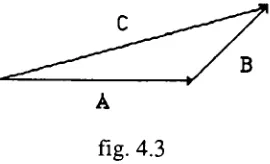
[image:16.526.95.218.503.620.2]4.6. Vectors: thegeometryof vector addition
Let AandBbevectors. If B isdisplaced sothatits initial pointisthe terminalpoint ofA,
the vector C from theinitial point ofA to the terminalpointofB is the sum ofA and B
[image:17.526.197.332.159.241.2](fig.4.3).
fig. 4.3
In section 4.4 we described each ofthe cartesian coordinates as directed distances from
planes through the origin. Let X, Y and Z be vectors corresponding to these directed
distances. For any point (x,y,z), the corresponding vector A is equal to the sum of the
vectorsX,YandZ,which whenplaced endtoend, willtraceapath fromtheorigin to the
point(x,y,z). See fig. 4.2.
4.7. Vectors: thecomponents fX,fYand fZ
Scalar Product geometric definition: Let A be avector, andc be a scalarconstant, then
the scalar productcA is avector with c times the magnitude ofA. The direction ofcA
willbe oppositethatofA ifcis negativeandthe same as thedirectionofAotherwise.
Let X, Y and Z be unit vectors (magnitude = 1) whose directions correspond to the
positivex, y andzaxisrespectively. Let A be a positionvectorinitiating fromthe origin
and terminating at the point (x,y,z) as in the previous section. When we say that the
vector A is represented by the triple <x,y,z> we mean that x, y and z are scalar
coefficientsofthe three unitvectors above such thatxX + yY + zZ = A. In this notation
the vectors X, Y andZare called a basis, and the scalarcoefficients x, y andz are called
the components of vector A. The data fields fX, fY and fX of TVector are vector
components.
4.8. Vectors: implementation ofvectoraddition
LetX, Y and Z be vectors and constitute a basis. Let A and B bevectors such that A =
B =aX + bY + cZ +dX
+ eY +fZ, orcollecting liketerms: A +B = (a+ d)X + (b + e)Y + (c +f)Z.
The TVector object has two vector addition methods: SumOf and AddTo. If aVector,
bVectorand cVector are oftype TVector then the statement : aVector.SumOf(bVector,
cVector), assignsthe sumofbVectorand cVectorto aVector.
The statement: aVector.AddTo(bVector), assigns the sum of aVector and bVector to
aVector. Note that in either case only the object whose method is called (aVector) is
modified.
4.9. Vectors: implementation ofthescalar product
LetX, Y andZ bevectors and constitute abasis. Let k be a scalarandA beavectorsuch
that A = aX + bY
-i-cZ where a, b and c are scalar constants. ThenkA = kaX + kbY +
kcZ.
IftheVector isan objectoftype TVectorandk is scalarthen the messageormethod call:
theVector.Scale(k),willmultiplyeachcomponentoftheVectorbyk.
Notes on scalar multiplication: If k = 1 then kA = A. Ifk = -1 then kA will be the
additive inverse of A. If the magnitude of A is 1 then the magnitude of kA is k. ChoosingX, Y,andZasunit vectors parallel totheirrespective axis provides abasis such
that the components <x,y,z> of a vector from the origin to a point correspond to the
cartesian coordinatesforthatpoint.
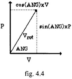
4.10. Vectors: rotationof avector in a plane
In aplane we candecompose any vectorinto a basis consisting of any twonon-parallel
vectors. Let V be a vector we wish to rotate ANG degrees. Let P be vector, of equal
magnitude, perpendicular to V. Ifwe use V and P as a basis for the vector we seek,
co8(ANG)xV
8in(ANG)xP
[image:19.526.202.327.44.180.2]V
fig. 4.4
Vrot=
(cos(ANG))V+ (sin(ANG)) P
The rotation method is equivalent to the vector sum of two scalar products. TVector objects respond to the method call or message: aVector.Rotate(angle, perpVector), by
rotatingaVectorangledegrees in theplanedeterminedbyaVectorand perpVector.
4.11. Vectors:the dot product
Let V = aX + bY + cZ and W = dX + eY + fZ, where X, Y, and Z are a basis and a,b,c,d,e, and f are scalar coefficients. Then the dot product ofV andW is the scalar obtainedby summing theproductsoftheircorrespondingcefficients (1) V-W=
(axe)+ (bxf) + (cx e).
If V andWare placedsothat theyhavethe sameinitialpointthenitcanbe shown, by the law ofcosines, thatthe sameresultisobtainedby theformula (2) V-W= IWI IVI
cos(A),
where A is the anglebetween V and W. The TVector.Dot function is implemented with formula (1), but the geometricinterpretation (theprojection ofVon Wmultiplied by the
Let W in formula (2) be a unit vector, then the magnitude ofW equals 1 and we have:
V-W = IWI IVI
cos(A) = IVI
cos(A), which is equal to the scalar projection of V on the
extensionofthevectorW.
This result can be used to implement a change in basis for a vector. Let V be a Vector andI, JandK be non-parallelunit vectors. I,J andKconstitute abasis. The coefficient fortheIcomponentofV isthe magnitudeoftheprojection ofVon aline inthedirection ofI orV-I (see fig. 4.5b). Thetriple <VI, VJ, VK> are the components ofV in theI,
J, Kbasis. Thecameraorviewpoint usedin animatorprojectionsis a basis similarto I, J,
4.12. Vectors: Implementation oftheTVectorObjectType
TVector=OBJECT
(TObject)
fX,fY, fZ: EXTENDED; {triple offloatingpointnumbers]
(TVectormethods}
PROCEDURE TVector.Init(x, y,z: EXTENDED); PROCEDURE TVector. CopyOf(v:TVector); PROCEDURE TVector.Sumof(vl,v2: TVector); PROCEDURE TVector. AddTo(v:TVector);
PROCEDURE TVector.Rotate(angle: EXTENDED; perp: TVector); PROCEDURE TVector. Scale(k: EXTENDED);
FUNCTION TVector.DotWith(v: TVector): EXTENDED; END; (TVector}
(ImplementationofVectorMethods)
PROCEDURETVector.Init(x, y, z: EXTENDED);
(Initialize data fieldsfX, fY & fZto x, y &z]
BEGIN fX:=x; fY :=y; fZ:=z
END; (TVector.Init)
PROCEDURE TVector.CopyOf(v:TVector);
(Initialize data fieldsfX,fY & fZ to v.fX, v.fY, v.fZ}
BEGIN fX :=v.fX; fY :=v.fY; fZ:=v.fZ
END; (TVector.CopyOf]
PROCEDURE TVector.Sumof(vl,v2: TVector);
(vectoris assignedthe sum of vl andv2]
BEGIN
fX:=vl.fX +v2.fX; fY:=vl.fY +v2.fY;
fZ:=vl.fZ+ v2.fZ
PROCEDURE TVector.AddTo(v: TVector);
(thevectorvisaddedto theobjectvector}
BEGIN fX :=fX +
v.fX;
fY:=fY +v.fY; fZ:=fZ +v.fZ
END; {TVector.AddTo}
PROCEDURE TVector. Scale(k:EXTENDED);
(vector ismultipliedbythe scalark)
BEGIN fX :=fX * k;
fY :=fY * k;
fZ:=fZ*k
END; {TVector.Scale}
PROCEDURE TVector.Rotate(angle: EXTENDED; perp: TVector);
(rotatesvectorangledegrees in theplanedeterminedbyvector
andperp, a secondvectorperpendicularto theobjectvector}
VAR
c,s: EXTENDED;
BEGIN
angle :=angle * gDEGRAD;
c :=Cos(angle);
s :=Sin(angle); Init(fX*
c +perp.fX * s, fY * c+perp.fY * s, fZ* c +perp.fZ* s)
END; {TVector.rotate}
FUNCTIONTVector.DotWith(v:TVector): EXTENDED;
(return dotproduct of vector object withv}
BEGIN
DotWith :=fX * v.fX +fY *
v.fY +fZ *
v.fZ
5. Local CoordinateSystemsand fheTLCS Ohiect Tvne
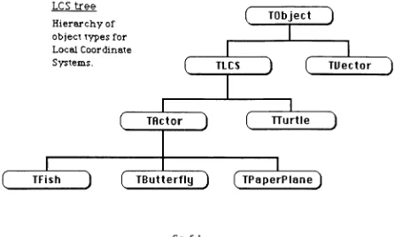
5.1. Local Coordinate Systems: theTLCS Object Type
The TLCS object type is the ancestor of all of Animator's actor types as well as the
graphicsturtle. It provides movement and rotation methodsforallofAnimator's moving
objects.
LCS tree
Hierarchyof
objecttypes for
Local Coordinate
Systems.
(
TObject)
TLCS
TActor
D
C
J
TTurtle
1
(
TFish)
(
TButterfly)
(
TPaperPlane)
TUector
)
[image:23.526.44.490.196.464.2]J
fig. 5.1
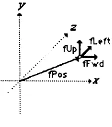
TLCS objects contain 4 vector fields: fPos, fFwd, fUp and fLeft, that store data about
position, heading and orientation in 3-dimensional space. An Object Pascal declaration
for the TLCS objecttype follows at theend of this section. The Position vector (fPos)
locates a LCS in space. The other three fields represent mutually perpendicular unit
vectors (see fig.5.2) thatestablishaheading (fFwd) and an orientationfortheLCS. Each
ofthevectordatafields is representedby an orderedtriple, <x,y,z>, relating itto a global
basis, but all orientation andmovement methods are implementedrelative to the local
basis determined by fUp, fFwd and fLeft. A fifth vector field, fTemp, facilitates
fig. 5.2
5.2. LocalCoordinate Systems: fYaw, ("Pitch and fRoll
The TLCS objects have three REALorEXTENDED datafields, fYaw, fRoll andfPitch,
used to store information about changes in orientation or angular momentum. These
values represent rotations aboutan axis ofthe local coordinate systems in degrees. The
yaw, pitch and roll terminology is often used to describe rotation in three-dimensional
space (nautical, aviation,robot motion).
Let yaw be a rotation ofthe vectors fLeft and fFwd about theaxis definedby fUp, pitch
be the rotation of fUp and fFwd about fLeft, and roll be the rotation of fLeft and fUp
about fFwd. Actors and graphics turtles reference these data fields to update their
orientation.
5.3. Local Coordinate Systems: fLensandfitsView
ThefLens field is only used by an LCS when it isfunctioning as a camera or viewpoint
for the 2-dimensional projection onto the screen. Earlier versions of Animator
implemented a camera object type, but the inclusion of the fLens in all LCS objects
allows any actor to be used as the viewpoint. The fLens data field is a REAL or
EXTENDED number used to scale the image. Image size on the screen is directly
proportional tothevalue offLens.
ThefitsView field isahandleordoublepointertoaMacApp TViewobject. Thepointer
allows any LCS object connected to a particular view to reference information in that
5.4. Local Coordinate Systems: allocation and assignment
If CS is declaredas aninstancevariableoftypeTLCS, thenit isahandle (double pointer)
whose value is undefined. The NEW command allocates memory to CS. The
initializationofits datafieldsis now acomplishedby sending messagesto CS inthe form
of method calls. Forexample, CS.Init(50,25, 40), is a messagetelling CS toinitialize its
position vectorto the triple <50,25, 40>. Theorientationvectors will be assigneddefault
values correspondingto thebasis oftheglobal coordinate system,withfFwd directed like the positive x-axis and fUp directed like the positive y-axis, as in fig. 5.2. If the
orientation is to be altered, rotation messages will direct CS to compute the new
components for the unit vectors fUp, fLeft and fFwd. The EXTENDED fields are
initialized to zeroand can beresetbymessages such as: CS.Yaw(90) andCS.Zoom(300),
which tell CS to set the fYaw field to 90 and the fLens field to 300respectively. Actors
override theTLCS. Init method in ordertoextend it. The inheritedmethod is, however,
calledby theTActor.Initoverride.
5.5. Local Coordinate Systems: deepand shallow methods
The Free methodde-allocates memory for an object. It is inherited from TObject by all
other objects, butmust be overridden by those objects whose data fields are themselves
dynamically allocated. The inherited method is called a shallow Free method and the
override thatfrees space allocated to each ofitspointertype fields is called adeep Free
method.
TLCS. Freemust freeeach ofits fivevectorobjects. Most descendantsofTLCS override
this methodin order todeal with additional fields forwhich memory has been allocated.
Typically, these deepfree methods call onTLCS. Free to finish thejob. Pointers such as
TLCS.ItsView, which serve as connections to independent objects need not, and in fact
should never be used tofree the memory that theyreference. TLCS.CopyOf is another
shallow method (copies fPos, fFwd, fUp andfLeftonly) that is overridden and extended
bymanyofits descendants.
Each of the rotation methods provided for the TLCS object type rotates two of the
orientation vectors about an axis alongthe third. Thesemethods exploit thefactthatfUp,
fLeft and fFwd (fig. 5.3) are mutually perpendicular unit vectors in two ways: (1) the
rotations are always within the plane determinedby the rotated pair ofvectors, (2) each
member oftherotated pair provides a perpendicualrunitvectorthatfacilitatestherotation
computationfortheother(see section4.10,rotationof a vectorin theplane).
fUp
,fLeft
I fFwd
fig5.3
TurnLeft and TurnRight rotate fLeft and fFwd about an axis along fUp. TiltUp and
TiltDown are rotationsoffFwd andfUp about fLeft. RollRightandRollLeftrotatefLeft
andffUp aboutfFwd.
5.7. Local CoordinateSystems: theTiltUp method
Let CS be a TLCS object, then the message CS.TiltUp(30), will rotate CS.fFwd and
CS.fUp 30 degrees about the axis determined by CS.Left in the direction from fFwd
towardfUp.
fFwd is rotated by the message fFwd.rotate(30, fUp). The second argument to rotate
must be a unit vector that is perpendicular to fFwd (90 degrees in the direction of
rotation). ForfFwd, the vectorfUp is therequired perpendicular. In orderto rotatefUp
we require a similar perpendicular which is not directly available, but easily computed.
Thecorrectvectorwould resemble fFwdwithits directionreversed. The TiltUp method
initializes fTemp to be the negative of fFwd, and sends the message fUp.Rotate(30,
fTemp). Theother rotations areimplemented similarly.
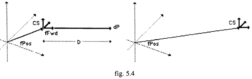
fPos
CS
[image:27.526.51.479.41.176.2]fPos
fig. 5.4
Let dP be a vector parallel to CS.fFwd with magnitude D, then dP is the vector
represention of the change in position or movement. dP is the product of the vector
5.9. LocalCoordinate Systems: Implementation ofTLCS ObjectType
TLCS =OBJECT
(TObject) (Local Coordinate System] fPos, (positioninglobalcoordinates)
fUp, (unitvectorproviding up/downreference} fLeft, {unit vectorforright/leftreference}
fFwd, (forward indicatesthe directionofmotion} fTemp:TVector; (usefulduringrotationsofLCS}
fLens: EXTENDED; (zoom factorwhen usedascamera}
fYaw, fPitch,fRoll: EXTENDED; (change inorientation perframe} fltsView: TLCSView; (linktoMacApp view}
(Local Coordinate SystemMethods}
PROCEDURE TLCS.Init(theView:TLCSView; x, y, z: EXTENDED); PROCEDURE TLCS.CopyOf(lcs: TLCS);
PROCEDURE TLCS.TurnRight(angle:EXTENDED);
PROCEDURE TLCS.TurnLeft(angle: EXTENDED);
PROCEDURE TLCS.TiltUp(angle: EXTENDED);
PROCEDURE TLCSTiltDown(angle: EXTENDED);
PROCEDURE TLCS.RollRight(angle: EXTENDED);
PROCEDURE TLCS.RollLeft(angle:EXTENDED); PROCEDURE TLCS.Move(distance: EXTENDED); PROCEDURETLCS.MoveAbs(x,y, z: EXTENDED); PROCEDURETLCS.Zoom(length: EXTENDED); PROCEDURETLCS.Free; OVERRIDE;
PROCEDURE TLCS.Yaw(delta: EXTENDED);
PROCEDURE TLCS.Pitch(delta: EXTENDED);
PROCEDURE TLCS.Roll(delta: EXTENDED);
END; (TLCS)
(Implementation ofMethods for Local Coordinate Systems}
PROCEDURETLCS.Free; OVERRIDE;
(deepfree for local coordinatesystem}
BEGIN
fPos.Free; fUp.Free; fLeft.Free; fFwd.Free;
fTemp.Free;
PROCEDURE TLCS.Init(theView:TLCSView; x, y, z: EXTENDED);
(initializelocalcoordinate system atx, y, zoriented likeglobalCS}
VAR
vl, v2, v3,v4: TVector;
BEGIN
fltsView :=theView;
new(vl);
vl.Init(x, y, z); fPos:=vl;
new(v2);
v2.Init(0, 1,0);
fUp :=v2; new(v2);
v2.Init(0, 0, 1); fLeft :=v2;
new(v3);
v3.Init(1,0,0); fFwd :=v3;
new(v4);
fTemp :=v4; fYaw :=0; fPitch :=0; fRoll :=0 END; (LCS.Init}
PROCEDURE TLCS.CopyOfdcs:TLCS);
(MakeobjectTLCS acopyoflcs)
BEGIN
fPos.CopyOf(lcs.fPos); fLeft.CopyOf(lcs.fLeft); fUp.CopyOf(lcs.fUp); fFwd.CopyOf(lcs.fFwd)
END; {LCS.CopyOf}
PROCEDURETLCS.TurnRight(angle: EXTENDED);
(rotateLocal Coordinate Systemangledegreesto theright}
fTemp.Init( fFwd.fX, - fFwd.fY,- fFwd.fZ); fFwd.rotate( - angle,fLeft);
fLeft.rotate( angle,fTemp)
PROCEDURETLCS.TurnLeft(angle: EXTENDED);
(rotateLocalCoordinateSystemangledegreesto thefLeft}
BEGIN fTemp.Init(
-fFwd.fX,
-fFwd.fY,
-fFwd.fZ);
fFwd.rotate(angle,fLeft);
fLeft.rotate(angle,fTemp) END; {LCS.TurnLeft}
PROCEDURETLCS.TiltUp(angle:EXTENDED);
(rotateLocal CoordinateSystemangledegreesupward}
BEGIN
fTemp.Init( fFwd.fX,
-fFwd.fY,
-fFwd.fZ); fFwd.rotate(angle, fUp);
fUp.rotate(angle, fTemp) END; (LCS.TiltUp}
PROCEDURE TLCSTiltDown(angle: EXTENDED);
(rotateLocalCoordinate Systemangledegreesdownward}
BEGIN
fTemp.Init( fFwd.fX, - fFwd.fY,- fFwd.fZ);
fFwd.rotate(
-angle, fUp); fUp.rotate(
-angle, fTemp) END; {LCS.TiltDown}
PROCEDURE TLCS.RollRight(angle: EXTENDED);
(roll Local Coordinate Systemangledegreesclockwise}
BEGIN
fTemp.Init( fLeft.fX,
-fLeft.fY, - fLeft.fZ); fLeft.rotate(angle, fUp);
fUp.rotate(angle,fTemp) END; {LCS.RollRight}
PROCEDURETLCS.RollLeft(anjgle: EXTENDED);
(rollLocalCoordinate Systemangledegreescounter-clockwise}
PROCEDURETLCS.Move(distance: EXTENDED);
(movesposition of objectbyamount specified asdistance in direction
ofthevectorcomponentfFwd}
BEGIN
fTemp.CopyOf(fFwd);
fTemp.Scale(distance); fPos.AddTo(fTemp);
END; {LCS.Move}
PROCEDURE TLCS.MoveAbs(x, y,z:EXTENDED); (setobject's position to x, y,z}
BEGIN
fPos.Init(x,y, z) END; {LCS.MoveAbs}
PROCEDURE TLCS.Zoom(length: EXTENDED); (setobject's lensequaltolength}
BEGIN
fLens :=length END; (LCS.Zoom}
PROCEDURE TLCS.Yaw(delta: EXTENDED);
(changetheangularvelocityabouttheverticalaxisbydelta}
BEGIN
fYaw := delta
END; (TLCS.Yaw}
PROCEDURETLCS.Pitch(delta:EXTENDED);
(changetheangularvelocity aboutthehorizontalaxisbydelta}
BEGIN
fPitch :=delta
END; {TLCS.Pitch}
PROCEDURE TLCS.Roll(delta:EXTENDED);
(change the angularvelocityabouttheforwardaxisbydelta}
BEGIN
fRoll:= delta
6. TheTurtle: aVector-Based GraphicPph
6.1. The Turtle: turtlegraphics
Theturtlemetaphor for scripting themotionofa graphics pen onthescreen ofa computer
demystified computer programming for a generation of school children who were
introduced to turtle graphics through the Logo programming language [Papert 1970].
Graphics turtles draw by 'dragging'
a graphics pen which marks theirpath as they obey
ordersto move andturn. Thepower ofthemetaphor seems tocome fromtheimmediacy
ofthecommands.
Beginningprogrammers learn Logo in an environment where eachcommandis executed
immediately, avoidingpossibleconfusionabouthowprevious commandshavealtered the
turtle's position or heading. The programmer must assume the turtle's point of view in
order to give proper instructions which take the form ofcommands like "turn left (90
degrees)"
or "move forward (10 steps)". Higher level commands are built up from
primitive ones as procedures orsub-programs.
Thefollowingexampleof aproceduretodrawa square is in aturtledialectsimilarto the
onedefined fortheTLCSobject typeintheLocalCS section ofthispaper.
procedure square(distance :extended);
begin
move(distance); turnleft(90); move(distance); turnleft(90); move(distance); turnleft(90);
Tur*le"
move(distance); turnleft(90); end; {square}
Notethatthesquares above areequallylikely outcomesofsendingtheSquare messageto
6.2. The Turtle: drawingan actor
From an analytic point of view, the unusual aspect of specifying a drawing in this
manneris the freedom ofthe descripion from any coordinate system. All lines, points
anddirectionsare relative to theturtle's inititialpositionandheading. Animatorexploits these procedural definitions of drawing to implement transformations: rotations and
translations are accomplished by altering the turtle's position before the drawing
procedureis begun.
In Animator, each actor has a method ofdrawing itself consisting ofa setof commands
for a graphics turtle. An actor is moved or rotated by messages modifying the position
and orientation data inits vectorfields. Similar fields are inheritedby all TLCS object
types, includingturtles. When an actor iscalled upontoredraw itself, itsendsits turtle a
messagetocopy theseposition and orientationvectors overitsown. Sinceall ofthelines
drawnbythe turtleare relativetoits initialpositionandorientation, theeffectis similarto
multyiplyingby atransformation matrixinaconventional graphicspackage.
6.3. The Turtle: TTurtleobjecttype- data fields
The TTurtle object type is descendant from theTLCS objecttype andinherits all ofthe
TLCS data fields and methods described in the Local CS section. These vector based
methods allow TTurtle objects to respond to messages to turn and move. The TTurtle
object typeadds thefollowingdatafields, which arespecific toits function.
The boolean field fVisible works with the PenUP and PenDown messages to
determine whether the moving turtle will draw a line or simply move to a new
position.
fCenterXandfCenterY locate the center ofthe screenfortheprojection method.
fViewPointis ahandle allowingthe turtles projection methods to access the data
fieldsofthecurrent camera.
fSave provides a place to save the position vector when a drawing is more
efficientlycompleted by moving backtopreviouslyvisitedpoint.
fPositionPitch, fPositionYawand fPositionRoll savedegrees of rotation about each
Animator's Rotation Menu commands use these fields in conjunction with the TTurtle
object's inherited fields fPitch, fYaw and fRoll to maintain and display angular
momentum about one or more axis that is independent ofthe rotationof the actor's local
coordinate system. The messagesto update thesefields and rotate the turtle are sent by
theTActor. DrawPoly method,just beforedrawingis begun.
6.4. The Turtle: projection ontothe plane
Assumingits fVisible field is settotrue (aTurtle.PenDown), aTurtleissues a commandto
draw aline from its initial position toits destination. In Animator this line is not drawn
immediatelyon the screen,but is collectedin aMacintoshtoolboxdata structurecalled a
Polygon, which is usedlikea segmentina displayfile.
The lines collectedinthe polygonareexpressed in theView's integercoordinate system,
an awkwardsystem with thepositive y-axispointingdown. TTurtle objectsrespond toa
message like aTurtle.Project byoutputtinga LineTo(x,y) command, where x andy are
View coordinates. The projection of the three-dimensional point associated with its
positiononto anx, yplaneisaccomplished bycomputinga new set of coordinatesforthe
point basedon the local coordinate system ofthe current camera, a TLCS object whose
datafields arereferencedthroughthefViewPointpointer.
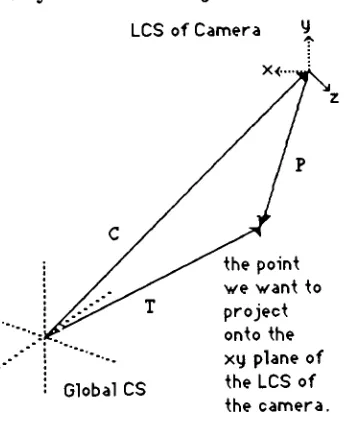
6.5. The Turtle : thegeometryofTTurtle.Project
LCS ofCamera 4.
Global CS
thepoint we want to project
onto the xy plane of
[image:34.526.184.356.412.623.2]Let C be the position vector ofthe cameraandT be the position vector ofthe turtle, then
P, a vectorfrom the tip ofCto the tip ofT can becomputed as thedifference between T
andC.
P - T-C, can also
be viewed as the positionvectorof the point to be projected from the
coordinate system ofthe camera. The vector Pcan be resolved into components ofthe
x,y,z basisof the cameraLCS by findingthedot productor scalar projection ofP on the
extensions ofeach of the unit vectors in the basis ofthe camera LCS. Drawing lines
between points obtained from the x and y components found above would produce a
parallelprojection(noperspective).
6.6. TheTurtle: perspective projection
Animator produces a three-dimensional perspective by multiplying each of the
coordinates found in the parallel projection by a ratio of a magnification factor,
fViewPoint.fLens, and the orthogonol distance of the projected point from the x,y
projection plane. The distance is simply the z component found by TTurtle.Project, and
fLens is a value set by TLCS.Zoom. Theresult is to shrinkthe projected coordinates of
distantobjects toward the center oftheprojection. IncreasingfLens magnifiesallobjects
equally.
TTurtle.Project then rounds the result and resolves the differences between the image
space coordinate system used by QuickDraw (Macintosh graphics package [Appl 85])
and Animator's world coordinates. If fVisible is true, a line is added to the polygon,
otherwise a QuickDraw call is made to MoveTo which moves the graphics pen to (x,y)
withoutdrawingtheline.
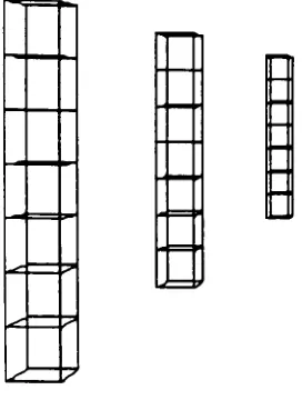
6.7. The Turtle: drawingwith the turtle
Thepostspicturedinfig6.3 weredrawn bythe turtle. Except fortheir z-coordinates they
are identical. The perspective and size differences are due to the projection. They are
made by repeated calls to the turtle's StackCube method, which draws a cube from the
lower, leftcomerandleaves theturtle atthe upper, leftcornerready todrawanothercube
s-s
s /
m=:>
.=p
[image:36.526.196.332.56.245.2]J '
fig. 6.3
The cube is drawn by having the turtle walkaround the block with left rums, pausingat
each corner todraw a squarewith tilt-up turns. An important strategy in designing turtle
subroutines, such as the tilt-up square, is to return the turtle to its initial position and
orientation. The advantagein thisexample is that the tilt-up squares do not complicate
thewalkaroundthe block.
6.8. The Turtle: overridinginheritedmethods
As an immediate descendantofthe TLCS object type, TTurtleobjects inheritall TLCS
methods. Several of these methods are useful but incomplete, in view of the TTurtle
object's specialization. A straightforward example is the inherited Move method. It
works fine, butunlike anyotherobject oftheTLCS type, turtlesneed todraw lines when
they move. The OVERRIDE method simply calls the INHERITED Move method
followed by the Project method. The MoveAbs method for transporting an LCS to a
position whose coordinates areknownisoverridden inthe same manner.
The Init method is similarly extended to accommodate additional data fields. A more
interesting case is the inheritedTLCS.CopyOfmethodwhich only copies fields common
to all descendants ofthe object type. This is particularly useful when the position and
It is, however, sometimes useful to make one turtle an exact copy (all data fields) of
another. The TTurtle OVERRIDE ofCopyOfwill make such acopy, if, andonlyif, the
argumenttoTTurtle.CopyOfisoftype TTurtle.
In theimplementationthemembershipoftheargumentin TTurtletypeistested andifthe
argumentisofthecorrecttype,typecoercionisusedtoassignahandleofthecorrecttype
to point to the data fields. In MPW Pascal, when a type identifier is used as a Pascal
functionthe argument isrecast as thedesignatedtype andreturned by the function. This
permits siblingobjects to bepassed as actual parametersto thesame routine,with noloss
ofinformation.
6.9. The Turtle: movingparts
Inthecaseofan overidden methodtheinheritedmethodis alsoavailablebyprefacingthe
callwiththereserved wordINHERITED. Inthecurrentversion ofAnimator,actorswith
parts that move independently are implemented with a single turtle. Increasingly
complex actors would be better served by multiple turtles, so that each turtle could
maintain static data about its orientation with respect to its immediate predecessor in a
hierarchical structure.
In such adesign, subordinate turtles wouldtake theirinitial positionand orientation data
fromotherturtles,rather thanfromtheactor. Inthis case theinheritedCopyOfwouldbe
appropriate, so as to avoid writing over data fields like fPositionPitch, which must
6.10. Turtle: ImplementationofTTurtleobject type
TTurtle= OBJECT
(TLCS)
fVisible: boolean; (moving turtledraws linewhen true}
fViewpoint: TLCS; (handleforcamera } fCenterX,fCenterY: EXTENDED; fSave: TVector;
fPositionPitch: EXTENDED; fPositionYaw: EXTENDED; fPositionRoll: EXTENDED;
PROCEDURETTurtle.PenUp; PROCEDURETTurtle.PenDown;
PROCEDURE TTurtle.CopyOf(lcs: TLCS); OVERRIDE; PROCEDURE TTurtle.ChooseCamera(vp: TLCS);
PROCEDURE TTurtle.Move(distance: EXTENDED); OVERRIDE;
PROCEDURE TTurtle. MoveAbs(x,y, z: EXTENDED); OVERRIDE;
PROCEDURETTurtle.Init(theView:TLCSView;x, y, z: EXTENDED); OVERRIDE;
PROCEDURETTurtle.Project;
PROCEDURE TTurtle. Square(side: EXTENDED); PROCEDURE TTurtle.Cube(side: EXTENDED); PROCEDURE TTurtle.StackCube(side: EXTENDED); PROCEDURE TTurtle.Triangle(side: EXTENDED); END; {TTurtle}
(Methodsforgraphicsturtle}
(initialize turtleusingx, y toestablish center ofCS andz forzoomvalue}
PROCEDURE TTurtle.Init(theView: TLCSView; x, y, z: EXTENDED); OVERRIDE;
VAR
vp: TLCS;
aVector: TVector,
BEGIN
INHERITED Init(theView,x, y, z); ChooseCamera(fltsView.fCamera);
new(aVector); fSave :=aVector,
fCenterX :=kCenterX;
fCenterY :=kCenterY;
PROCEDURE TTurtle.CopyOf(lcs:TLCS); OVERRIDE;
VAR aTurtle: TTurtle;
BEGIN
INHERITED CopyOf(lcs);
IF MEMBER(lcs, TTurtle)THEN BEGIN
aTurtle :=TTurtle(lcs); fYaw := aTurtle.fYaw; fPitch := aTurtle.fPitch;
fRoll :=
aTurtle.fRoll; fPositionYaw:=aTurtle.
fPositionYaw;
fPositionPitch :=
aTurtle.fPositionPitch;
fPositionRoll :=
aTurtle.fPositionRoll;
fVisible :=aTurtle.fVisible;
fViewPoint :=aTurtle.fViewPoint
END {if}
END {TTurtle.CPOf} ;
PROCEDURETTurtle.Project;
(projectturtleposition with respect toplane ofviewingeye)
VAR
px,py: EXTENDED; {projection cooordinatesfor imagespace]
x, y, z:EXTENDED; {coordinates in viewpoint'sLCS}
BEGIN
fTemp.CopyOf(fViewPoint.fPos);
fTemp.Scale( 1); fTemp.AddTo(fPos);
x :=fTemp.DotWith(fViewPoint.fFwd);
y :=fTemp.DotWith(fViewPoint.fUp);
z :=fTemp.DotWith(fViewPoint.fLeft);
px :=x * fViewPoint.fLens/z +fCenterX; py :=fCenterY
-y* fViewPoint.fLens/z; IF fVisible THEN
LineTo(ROUND(px), ROUND(py)) ELSE
MoveTo(ROUND(px),ROUND(py));
END; (project)
PROCEDURETTurtle.PenDown;
(setvisibleto truesomovementdrawslines}
BEGIN
fVisible :=True
PROCEDURETTurtle.PenUp;
(setvisibletofalseso movementdoesn't drawlines}
BEGIN
fVisible :=FALSE END; {TTurtle.PenUp}
PROCEDURE TTurtle.ChooseCamera(vp: TLCS);
(assign vp as camera viewpointfordrawing}
BEGIN
fViewPoint:= vp
END;
PROCEDURETTurtle.Move(distance: EXTENDED); OVERRIDE;
(The inherited TLCS.Move isextendedtoproject and output a2-D linetocommand}
BEGIN
INHERITED Move(distance); Project
END; {TTurtle.Move}
PROCEDURETTurtle.MoveAbs(x, y,z: EXTENDED); OVERRIDE;
(The inheritedTLCS.MoveAbsisextendedtoprojectandoutputa2-Dlinetocommand}
BEGIN
fPos.Init(x,y, z); Project
END; {TTurtle.MoveAbs}
PROCEDURETTurtle.Square(side:EXTENDED);
(drawstate transparentsquare)
VAR
i: INTEGER;
BEGIN
FOR i:= 1 TO 4 DO BEGIN
Move(side);
TiltUp(90)
PROCEDURE TTurtle.Cube(side: EXTENDED);
{drawstatetransparentcube)
VAR
i: INTEGER;
BEGIN
FOR i := 1 TO 4 DO
BEGIN Square(side); Move(side); TurnLeft(90)
END;
END; {TTurtle.Cube}
PROCEDURETTurtle.StackCube(side: EXTENDED);
(drawscubes oneontopofanother)
BEGIN
Cube(side); TiltUp(90); Move(side); TiltDown(90); END;
PROCEDURETTurtle.Triangle(side:EXTENDED);
{drawsstate transparenttriangle)
VAR
i: INTEGER;
BEGIN
FORi:= 1 TO 3 DO
BEGIN
Move(side);
TurnLeft(120) END; (for)
7, Actors; a TemplateforPictures thatMovp
7.1. Actors: an animated objecttype
Animator's actors maintain data about their postion in the world coordinate system and
how thatposition is changing (instantaneous velocity, acceleration, angular momentum
and acceleration). They are designed to remain in motion (change their position and
orientationbeforeeach frameisrecorded) untiltheyreceive amessageto altertheirdata.
Animator'smenu and mouse controls allow usersto stop the actor's clockworkworld and
senditmessages. Actorsalso respondtomessages fromobjects (TView) thatcontrol the
image drawn onthemonitor. The design anticipates moreinterestingdescendantswhose
behavior might be modified by messages fromother objects in the scene, perhaps even
fromother actors.
As TActorobjects, actorscan storeinformation in theirdatafields and respondto certain
messagescorresponding to theirdeclared methods. When anew objecttypeis declared
tobeadescendantof anexistingoneitcan add toormodify its inheritance ofdata fields
and methods. EachofAnimator'sactortypescan trace its ancestry backthroughTActor
to theTLCS objecttypeandTObject. (recallfig. 5.1)
LCS tree
Hierarchyof
object typesfor
LocalCoordinate
Systems.
c
TActor(
TObject)
TLCS
D
C
TTurtleJ
(
TUector)
J
C~
7.2. Actors: TActor datafields
The data fororientation and position is stored invectorfields inherited from the TLCS
object type. They are discussed in detail in the sections Local CS and Vectors. The
TActor object typedeclares the followingadditional data fields in ordertomaintain and
update adisplayimage:
fPoly is a handle or double pointer to a QuickDraw data structure called a
Polygon. Polygons are used to store line drawing commands which can be
displayed with a single FramePoly commandwhen the view sends a message to
an actortodraw itself.
fValidPoly is a boolean field which is set to false if an actor or the camerahas
been moved or rotated, indicating it will be necessary to update the Polygon
before display.
fTurtle is ahandle forthegraphicsturtlewhich will beused to redrawthe actor's
Polygon.
fExtent is arectangle defining the area ofthe View effected by erasing theold
Polygon andframing the newone.
f/elocityis afield indicating thedistance an actor should bemoved in the next
frame.
fAcceleration is an increment or decrement applied to fVelocity before each
move.
fID is anidentification number.
fHiLight indicatesthatan actoris currently selectedand should be shaded on the
display.
7.3. Actors: Updatingthe Polygon
Whenever an actor has received a message to move or rotate it will set fValidPoly to
false. The TActor.InvalidatePoly method affords other objects (such as the View) the
opportunity of sending an actora message to invalidate its polygon. The View object
otherwise alters the viewpoint of projection. Before a view is redrawn an UpDate messageissenttoall actors whose fValidPoly field is false.
Topreparefordrawing,TActor.UpDatePolyfirstsends a messageto theobjectpointedto
by fCamera to initialize the projection coordinate system (projection onto the plane is
described in theTurtle section). Next, the boundingrectangle ofthe existingpolygon is saved (this area of the view will have to be redrawn), and a new one is initialized. Finally, messages are sent passing the actor's local coordinate system to the graphics
turtle andinstructingthe turtle toredrawthepolygon.
7.4. Actors: OverridingDrawPoly
TActor is an abstract object type. It serves as a template forall descendant actortypes, but is never instantiated. The DrawPoly method inherited by each of TActor's descendantsmakes somefinaladjustments to the turtle toaccountfortransformations that
are independentofthe actor's coordinate system, but doesnot contain any instructions for drawing. Each descendant of TActor must OVERRIDE the INHERITED DrawPoly
methodin ordertoprovide an appropriate method fordrawing itself. Typically thenew methodwillcalltheinherited oneto takeadvantageofthegeneralroutinesit implements. The drawing method consists of messages to move the graphics turtle, which in turn issuesQuickDrawcommandstocreate thepolygon.
Upon completion of the polygon, control returns to UpDate, and the polygon data structure is closed. The bounding rectangle of the new polygon is then combined with
that ofthe original polygon to provide a description ofthe portion ofthe view area that has been alteredby the update. Finally, theUpDate method resets fValidPoly to true.
7.5. Actors: moving the picture
production program that will create the frames for scripts involving the simultaneous
movementof a cast ofactors, butimplementationofaframe-by-frameproduction system
was not attempted.
Anactor'smovement betweenoneframeandthenextisrepresentedas adirected distance
(vector)takingits direction from theactor's headinganditsmagnitudefromthe datafield
fVelocity. Animator's interface allows the user to select a single actor, in order to
preview its progress as the framecounteradvances, by double clicking onthat actor and
holding down themouse button. Releasingthemousebutton willhaltthe process. Ifthe
halted sequence was not satisfactory itcan be undone (the actor will revertto its initial
position) witha menu command.
The user can stop and start the production of frames in order to change the value of
fVelocity. Sincethesemodificationsaltertheactor'sspeedabruptly, smoothtransitions to
new states would require many stops for small modifications. The user may instead
choose to modify fAcceleration, specifying an increment or decrement in velocity to be
appliedbeforeeach movementis computed,thus avoidingthe frequentkeyingthatwould
otherwise berequiredtospecifygradual changes.
Since movement will always be directed along the actor's heading, the user is also
providedwith theoption of rotating theactorso astochange theheading. Thechangein
direction can beeither immediateor incremental (per frame). Anincremental changeis
achievedby modifyingangular momentum. Itcan be likened to theinfluence ofarudder
ontheheadingofaboat,orthe steeringwheelontheheadingofa car.
7.6. Actors: Navigation in 3-D space
Rotations in Animatorarerelative to the actor'sheading andorientation ratherthan toan
external reference. The user is asked to assume the point of view of the actor he is
directing, or even better, to assume the actor's position in space. Left is the direction
pointed to by the extended left arm, and up isdirectly over the actor's head, even ifthe
actorhappensto beupsidedown. Althoughthisisoccasionally counterintuitive,the local
Up
Left.
<
= Fwdfig.7.2
When directing Animator'sactors, leftand right turns are bestunderstoodas rotationsof
fig. 7.2 in which the left and forward axes will rotate together, pivoting around the UP
axis. Tilting up or down is a rotation in which UP and FWD move together pivoting
around the LEFTaxis. Rolling leftor rightproduces a rotation ofUPand LEFT about
FWD (nochangeinheading).
The commands: Turn, Tilt, Roll and Acceleration are found in the Control Menu, and
operate on the currently selected actor. Rotations that do not affect the movement of
actorsthrough space (i.e. spinning) can be specified withthe Rotation Menu in a similar
manner.
The move command inherited from the TLCS object type takes a DISTANCE as a
parameter and moves the object forward along its present heading. The TActorobject
type overrides this method in order to make changes in orientation and compute an
appropriatedistanceparameterbasedon fAccelerationandfVelocity. The inherited fields
fYaw, fPitchandfRoll,correspondto rum, tiltandrollrespectivelyand are usedto record
rotationstobe madebeforeeach move orframe.
7.7. Actors: Descendants ofTActor
Creatinga new actortyperequires some programming inorder to describe how thenew
object will differ from its ancestor. For instance, if the actor is to differ only in
appearance,onlytheTActor.DrawPolymethod needbechanged(overridden).
Currently the most successful actors are of the TFish object type. They are paper thin
angelfish made oftwotriangles. Thesmallertriangle, ortail, swishesbehindthemoving
fishasitswims. The necessityofredrawingthepolygonsforeach movedictatesa simple
design,where realtimefeedback isrequired. Inframe-by-frameproduction, adescendant
ofTFish thatwasvisuallymoreinteresting, but slowertodraw, couldbe used to produce
the finalframes. Thenewfish needdiffer only in itsDrawPolymethod.
7.8. Actors: commandsastext
In anticpation of an application for the production of Animator scripts each menu or
mouse commandthatalters theappearance or position of an actor could bewritten astext
to anotherfile. Thetextdescription shouldinclude theselected actor'sIDnumber andthe
current frame number, as well as the data entered to complete the command. All
commands would bewritten toatext filewhich can be sortedaccording toframenumber
and editedtocreate scenes.
Theproduction applicationwoulddraw framesoneatatime, usingthe command fileas a
script. Inordertodraweach frame, itwouldexecuteall ofthecommandswith thatframe
number, move anddisplayeachactor, and thensignal a camera torecordthe frame. The
existing design should support scripts that choreograph multiple actors with a moving
camera or viewpoint. Production would be slow, but time increases should remain