UNIVERSITI TEKNIKAL MALAYSIA MELAKA
PROTOTYPE DEVELOPMENT OF THERMAL COMFORT
LEVEL CONTROL IN A MEDIUM DISTANCE FLIGHT
This report submitted in accordance with requirement of the Universiti Teknikal Malaysia Melaka (UTeM) for the Bachelor Degree of Engineering Technology
(Bachelor of Mechanical Engineering Technology in Refrigeration and Air-Conditioning System) with Honours
By
DEBIE DEVISSER GERIJIH B071310100
900629-13-7594
UNIVERSITI TEKNIKAL MALAYSIA MELAKA
BORANG PENGESAHAN STATUS LAPORAN PROJEK SARJANA MUDA
TAJUK: Prototype Development of Thermal Comfort Level Control in a Medium Distance Flight
SESI PENGAJIAN: 2015/2016 Semester 2
Saya DEBIE DEVISSER GERIJIH
mengaku membenarkan Laporan PSM ini disimpan di Perpustakaan Universiti Teknikal Malaysia Melaka (UTeM) dengan syarat-syarat kegunaan seperti berikut:
1. Laporan PSM adalah hak milik Universiti Teknikal Malaysia Melaka dan penulis. 2. Perpustakaan Universiti Teknikal Malaysia Melaka dibenarkan membuat salinan untuk
tujuan pengajian sahaja dengan izin penulis.
3. Perpustakaan dibenarkan membuat salinan laporan PSM ini sebagai bahan pertukaran antara institusi pengajian tinggi.
4. **Sila tandakan ( )
SULIT
TERHAD
TIDAK TERHAD
(Mengandungi maklumat yang berdarjah keselamatan atau kepentingan Malaysia sebagaimana yang termaktub dalam AKTA RAHSIA RASMI 1972)
(Mengandungi maklumat TERHAD yang telah ditentukan oleh organisasi/badan di mana penyelidikan dijalankan)
Alamat Tetap:
1403, Kenyalang Park
Jalan Upland. 93300
Kuching, Sarawak
Tarikh: ________________________
Disahkan oleh:
Cop Rasmi:
Tarikh: _______________________
DECLARATION
I hereby, declared this report entitled “Prototype Development of Thermal Comfort Level Control in a Medium Distance Flight” is the results of my own
research except as cited in references.
Signature : ……….
Author’s Name : ………
APPROVAL
This report is submitted to the Faculty of Engineering Technology of UTeM as a partial fulfillment of the requirements for the degree of Bachelor of Electrical Engineering Technology (Refrigeration and Air-Conditioning System) with Honours. The member of the supervisory is as follow:
………
i
ABSTRAK
Tujuan kajian adalah untuk membangunkan prototaip alat yang boleh memberikan
penumpang pesawat untuk suhu yang sesuai di dalam kabin penumpang dalam
penerbangan jarak sederhana. Ini dilakukan dengan mengambil beberapa perkara
penting seperti suhu kabin pesawat, tahap keselesaan terma penumpang, dan sistem
penghawa dingin pesawat jarak sederhana. Kaedah konvensional yang digunakan di
dalam pesawat untuk memanaskan badan penumpang adalah dengan mengedarkan
selimut kepada penumpang sejuk atau dengan mengurangkan isipadu udara. Walau
bagaimanapun, kaedah ini masih tidak begitu berkesan. Prototaip ini telah
dibangunkan untuk melaksanakan pemanasan hydronic dan kaedah penyejukan
kepada sistem. Kaedah ini tidak digunakan sepenuhnya di Malaysia tetapi telah di
pasaran antarabangsa untuk beberapa waktu dengan tambahan daripada suhu
Digital Pengawal termostat sensor. Pemanas telah dipasang untuk memanaskan air
yang sedang dipam ke dalam tiub yang beredar pada jaket haba. Dengan
memindahkan haba dari air untuk manusia melalui jaket, tahap keselesaan haba telah
dicapai. Prototaip dapat meningkatkan suhu dari 22 ° C ke 25 ° C dalam masa 15
minit. Dengan prototaip siap, ia boleh membantu untuk individu kawalan suhu
mengikut mana-mana penerbangan jarak sederhana, sekali gus mewujudkan suhu
tahap keselesaan terma di dalam pesawat. Tambahan pula, dengan menggunakan
peranti prototaip dalam tangan, penumpang tidak perlu bimbang tentang bagaimana
sumber udara sejuk dibekalkan (dalam hal apa-apa pencemaran udara).
ii
ABSTRACT
The purpose of this research is to develop a prototype device which can provide aircraft passengers a suitable temperature inside the passenger cabin in a medium distance flight. This is done by taking a few important matters into consideration such as the temperature of the aircraft cabin, thermal comfort level of passengers, and the air-conditioning system of a medium distance aircraft. The current conventional method used in an aircraft to warm up the passengers is by distributing blankets to the cold passengers or by decreasing the air volume. However this method is still not very effective due to the confined spacing. The prototype was developed by implementing hydronic heating and cooling method to the system. This method has not been fully applied in Malaysia but has already been in the international market for quite some time with an additional of a Digital Temperature Controller Thermostat Sensor. A heater was installed to heat up water which afterwards being pumped into tubes that circulates on a thermal jacket. By transferring the heat from the water to human through the jacket, the thermal comfort level was achieved. The prototype able to increase temperature from 22°C to 25°C in 15 minutes. With the finished prototype, it can help to control temperature individually according to personal reference in any medium distance flight, thus creating a thermal comfort level temperature in the aircraft. Furthermore, by using the prototype device in hand, passengers will not have to worry on how the cooled air source is supplied (in case of any air pollution).
iii
DEDICATION
I would like to thanks by beloved mother, Mdm Rowena Arnold for her unconditional support with my studies especially during the progress of this project. I am honoured to
have my family with me. Thank you for giving me a chance to prove and improve myself through all of my walks and throughout the journeys I have been through to complete this report. I love you! Thank you once again for believing in me, for allowing
iv
ACKNOWLEDGEMENT
v
TABLE OF CONTENT
Abstrak i
Abstract ii Dedication iii Acknowledgement iv Table of content v List of table viii List of figures ix List of Abbreviations, Symbols and Nomenclatures x CHAPTER 1: INTRODUCTION 1 1.1 Background 1 1.2 The purpose for this research 3 1.3 Problem statement 3 1.4 Objective 4 1.5 Scope of research 4 1.6 Proposed solution 4 1.7 Summary 5 CHAPTER 2: LITERATURE REVIEW 6 2.1 Aircraft air conditioning system 6 2.1.1 Environmental Control System 8
2.1.1.1 Air conditioning system 10
2.1.2 Air distribution 11
2.1.3 Ventilation system 13
2.1.4 Importance 14
vi 2.2.2 Ventilation for Acceptable Indoor Air Quality 17 2.2.3 Air Quality within Commercial Aircraft 18 2.3 Pilots, cabin crew, and passengers on board 18
2.3.1 Metabolism 19
2.3.2 Clothing insulation 19 2.3.3 Relative humidity 19 2.3.4 Thermal sensitivity of individuals 20 2.3.5 Gender differences 20 2.4 Hydronic heating system 21 2.4.1 Radiant heating 22 2.4.2 Basic component for hydronic heating 23 2.4.3 Convective heat transfer 24 2.4.3.1Free or natural convection 24 2.4.3.2 Forced convection 24 2.4.3.3 Internal and external flow 25
2.5 Summary 26
CHAPTER 3: METHODOLOGY 27
3.1 Project flowchart 27
3.1.1 Design 28
3.1.1.1 System Selection 29 3.1.1.2 Proposed Design 30 3.1.1.3 Study of materials 31
3.1.2 Fabrication 33
3.1.2.1Material Selection 33 3.1.2.2 Assembly / Setup of prototype 34 3.1.3 Experimental work 35 3.2 Billing of Materials (BOM) 36
vii
CHAPTER 4: DISCUSSION AND RESULTS 37
4.1 Methods of data analysis and presentation of data 37 4.2 Discussion of findings and results 38 4.2.1 Data used as reference for calculation 39 4.2.1.1 Heat transfer through convection mode 39 4.2.2.2 Thermal conductivity (k) of convective heat transfer 40 4.2.2Results obtained from experiment conducted 41 4.2.3Graph of surrounding temperature and water temperature vs time taken 42 4.2.4Calculation of heat transfer produced by heater 44 4.2.5Percentage error (%) of heater 47 4.2.6Psychrometric chart 48
4.3 Limitations 50
4.3.1Not suitable for area with temperature lower than 21°C 50 4.3.2Only for individual thermal comfort 51 4.3.3Not waterproof or water resistance 52 4.3.4Not suitable for children 53 4.3.5Restricted to get on board a flight 54
4.4 Future research 55
4.4.1Suitable DC heater 55 4.4.2Suitable material used on prototype 56 4.4.3Suitable design of prototype for safety purpose 56
4.5 Implementations 57
4.5.1Implementations for improvements 57 4.5.2Implementations for new product design 58
4.6 Summary 59
CHAPTER 5: CONCLUSION AND RECOMMENDATION 60
5.1 Conclusion 60
5.2 Recommendation 63
REFERENCE 64
viii
LIST OF TABLES
3.1 Materials used for assembly and fabrication of prototype 31 3.2 The selected materials to develop the prototype 33 3.3 Bill of material (BOM) 36
4.1 The value of h for convection mode 40
ix
LIST OF FIGURES
2.1 Aircraft air conditioning system 7 2.2 Aircraft Environmental Control System 9 2.3 The working system of hydronic heating system 21 2.4 Hydronic system with a boiler in a typical location 23 2.5 The general heat transfer for convection mode 25
3.1 The sequence of methodology through flowchart 28 3.2 Schematic of tank less hydronic heating system for both heating & cooling 29 3.3 Schematic drawing of the proposed device design 30
x
LIST OF ABBREVIATIONS, SYMBOLS, AND
NOMENCLATURE
ACS - Air Conditioning System APU - Auxiliary Power Unit
ASHRAE - American Society of Heating, Refrigerating, and Air-conditioning Engineers
BDP 1 - Bachelor Degree Project 1 ECS - Environmental Control System
EICAS - Engine Indication and Crew Alerting System EPS - Environmental Protection System
FACE - Friendly Aircraft Cabin Environment IAQ - Indoor Air Quality
ICE - Ideal Cabin Environment
1
CHAPTER 1
INTRODUCTION
1.0 Introduction
In this chapter, introducing the title of Bachelor Degree Project 1 (BDP 1) as well as little background on why such title is chosen and how the problem came about. The title of my project is “Prototype Development of Thermal Comfort Level Control in a Medium Distance Flight”.
1.1 Background
It is very hard to achieve a certain thermal comfort level especially when in an aircraft and is flying way up in the sky. Fewer things can be done when inside a vessel such as an aircraft and that includes installing a bigger fan on a hot weather or turning the heater on in a winter’s day. As defined by Pang Liping (2014), passengers on board domestic and international flights are becoming more and more demanding in terms of comfort. Therefore, further actions should be taken in order to achieve the suitable thermal comfort level for passengers.
This thesis reports about a thorough investigation on the thermal comfort level of passengers in a medium distance flight as well as its solution to create a temperature control device portable and is not against the flight boarding rules and regulations. Medium distance flight is a domestic flight which travels for 2 to 3 hours. The study also revolves around the inside of the aircraft such as the cabin environmental temperature and the passengers’ comfort level.
2 decreased depending on the environment. Besides that, ambient temperature is hard to control. Therefore a device is created to control the temperature and give out the best temperature for thermal comfort level. There are many types of temperature control and portable devices are now available for sale in the market. However, the usage of such device is very limited.
Human thermal comfort level is essential for everyday lives but especially for passengers on board Boeing 737. Thermal comfort is difficult to measure because it depends mostly on air temperature, humidity, radiant temperature, air velocity, and clothing levels of each individual on board the aircraft. Passengers tend to experience these sensations a bit differently based on individual’s physiology state. Boeing 737 travels only in a medium distance range but that does not make flying short to medium distance trip any less comfortable.
Previous case study showed that the European aviation had also carried out two famous projects, friendly aircraft cabin environment (FACE) and ideal cabin environment (ICE), to investigate and improve cabin comfort. The projects emphasized more on thermal comfort in an aircraft. This shows that even foreign countries are taking this matter seriously and are taking it into their own hands. While foreign countries are concern on passengers’ comfort level in the aircraft cabin, Malaysia should also take this matter seriously and should consider upgrading the current comfort level of local aircraft cabin.
There are many products on the market that sells devices such as a portable air-conditioning device, portable USB fans, and many other cooling devices which can contribute to human’s thermal comfort level. As many other products, not all the devices fulfill the desire of an individual. Hydronic system is chosen for this project because there are many benefits from using this system. Further studies and comparisons will be done through this report.
3
1.2 The purpose of the research
The purpose of this research is to overcome the thermal comfort level issue when in a medium distance flight and create a suitable prototype to control the temperature inside of an aircraft. According to National Research Council (2002), the environmental control system (ECS) in an aircraft is different from ECS used in other applications, because it must be able to operate in extreme temperatures, ambient air quality, and air pressure.
Results from current studies of thermal comfort level in an aircraft shows that not all aircraft is facing the same problem. Some passengers might travel luxuriously in the comfort of a business class cabin and some might just settle down in economy class with fair treatment. However, problems involving thermal comfort level for medium distance passengers are the main issue nowadays.
By the end of this report, a functioning prototype of such device should be created to overcome any issue on thermal comfort in a medium distance flight. The testing and experimental work will be done to assure the device functions.
1.3 Problem statement
Thermal comfort level is very hard to obtain nowadays especially in a vessel such as Boeing 737 which only travels from short to medium distance flights. According recent studies, despite the various innovations to improve passengers’ comfort while on board, very few individuals would describe any flight as truly relaxing.
4
1.4 Objective
Based on the research title, “Prototype Development of Thermal Comfort Level Control in a Medium Distance Flight”, the objectives below are pursued.
a) To develop a prototype of temperature controlling device.
b) To use and apply hydronic heating system with Digital Temperature Controller Thermostat with Sensor.
c) To achieve the thermal comfort level in a medium distance flight.
1.5 Scope of the research
The study focuses on the thermal comfort level of passengers in an aircraft for medium distance flight. Important parameters also include temperature and passengers in cabin.
1.6 Proposed solution
Hydronic heating system is one of the most famous methods to and the number of usage is increasing. This will be the main method when carrying out this study. This heating system is chosen because not many are exposed to this type of heating system although it has been widely used throughout countries with four seasons. The motivation on using the selected method is that it involves less complicated components as it is required to create a portable device and no pollution issue will arise as circulation of air is involved for this particular device.
5
1.7 Summary
Based on the products and materials that will be used for this prototype, all products are already in the market and should be able to easily be assembled. Here, the temperature controller plays an important role as it controls the required temperature to achieve a thermal comfort level.
6
CHAPTER 2
LITERATURE REVIEW
2.0 Introduction
In this chapter, there are briefings from a few journals and some other resources such as books on how aircraft AC system works, the meaning of thermal comfort in aircraft cabins, and how it affects the people on board the aircraft.
2.1 Aircraft air conditioning system
Air conditioning involves in the process of changing the air properties most commonly change in temperature and humidity, to a more comfortable condition, mainly to distribute the conditioned air to an occupied space such as a building or a vehicle to improve thermal comfort and indoor air quality (Wikipedia, 2016)
In the aeronautical world, the passenger comfort has become an important element and choice criterion for airline users. Today, air travel is becoming increasingly more accessible to people, both through the availability of cheap flights and also because the airlines are now able to transport individuals of all ages and disabilities. This is why the travelling condition should be comfortable for passengers who travel by flight regularly.
7
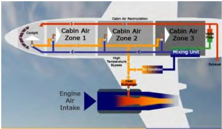
Figure 2.1: Aircraft Air Conditioning System
Air conditioning and pressurization are two very important components for any modern aircraft to fly any high altitudes, which according to Junaidi Ali (Air Conditioning and Pressurization System in Modern Aircraft, 2012) provides a convenient environment for its passengers. Due to low pressure in the atmosphere, the human body is unable to withstand its effect, which makes both air conditioning and pressurization system a vital component in the modern aircraft.
This is also quoted by Liebherr (Air conditioning, Air Management System) saying that air conditioning system creates a safe and comfortable environment for crews and passengers inside the aircraft cabin. A significant amount of cooled fresh air is then brought into the pressurized cabin in order to maintain a comfortable cabin environment as well as to ensure avionics and electronics cooling and ventilation.
8 Air conditioning system not only a vital component but it is also a necessity to have in every modern aircraft to ensure that the flight offers the passengers on board a safe and comfortable experience throughout the flight trip. Of course, there are many types of air conditioning system in the ECS itself due to aircraft spacious areas and different compartments in the aircraft such as the cockpit, the passenger’s cabin, cargo bay and many more. The air conditioning system in an aircraft will be further explained in the subtopics along with the progress of this report.
2.1.1 Environmental Control System (ECS)
Environmental control system or ECS (as shown in figure 2.2) is a system which provides conditioned air to the occupied spaces or areas and to the avionic cooling system. ECS caution and warning alerts can be seen on the engine indication and the crew alerting system (EICAS) primary display.
According to Northwest Airlink (Flight Crew Operating Manual, vol 1), the ECS systems such as pneumatic, air conditioning, and pressurization controls are located on the respective overhead bleed air, air conditioning, and cabin press panels. Cockpit instrument panels are cooled through forced of ventilation air.
9
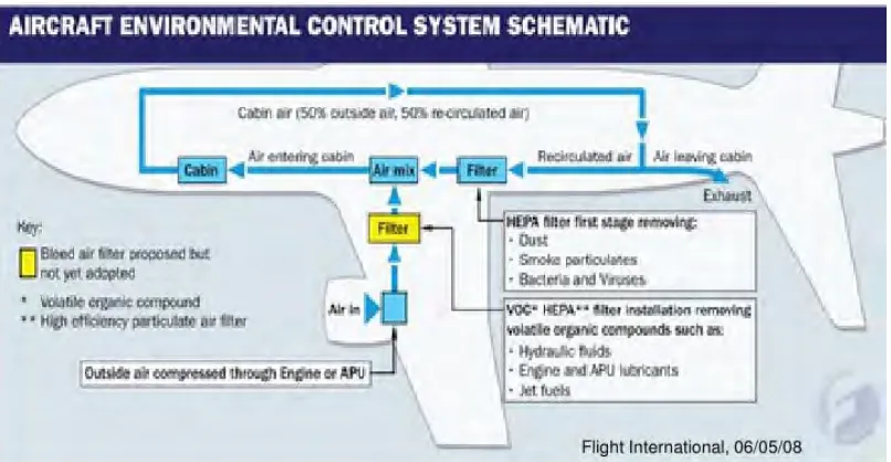
Figure 2.2: Aircraft Environmental Control System
Isidoro Martinez (Aircraft Environmental Control, 2016) states that the ECS is an important and vital equipment or device to ensure that the comfortable cabin condition in the aircraft is achieved and maintained by keeping the all the important parameters of air conditioning such as temperature, pressure, and composition is within the acceptable limits, usually by circulating a fluid for thermal control and life support, if required.
It is also stated that ECS for vehicles in hostile environments is most high demand but it usually only focuses on the inside part of the vehicle whereas the environmental control of the outer side is usually called the environmental protection system (EPS) which will not be included for this report. Besides that, report will focus more on hydronic system because the regulations of the airport need to be followed.
10 Omer Majeed (2010) also states that ECS comprises various systems performing the functions such as bleed air supply, bleed leak detection, air conditioning, distribution, avionics cooling, cabin pressurization control, and oxygen supply on transport category aircraft. All aircraft must perform their intended function under any visible operating condition and allow safe continuation of the flight.
2.1.1.1 Air conditioning system
In an aircraft, the air conditioning system provides ventilation and temperature regulation in the occupied spaces and areas. The system consists of two independent air conditioning packs and a ram air ventilation system. The air conditioning packs normally work in parallel to accomplish compartment temperature control.
Each of the air conditioning pack in the aircraft is normally supplying bleeding air from the onside of the aircraft engine. The auxiliary power unit or APU directly feeds the left pack. A pressure regulating shutoff valve controls the bleed air flow to each pack which is controlled by the respective pack switch lights on the air conditioning panel. This is all according to Northwest Airlink (Flight Crew Operating Manual, vol 1), which should be similar to all Boeing 737 flights.