i
SOLAR PEAK POWER TRACKER
MOHD FAHMI BIN IDRUS
This report is submitted in partial fulfillment of the requirements for the award of Bachelor of Electronic Engineering (Telecommunication Electronics) With Honours
Faculty of Electronic and Computer Engineering Universiti Teknikal Malaysia Melaka
iii
“I hereby declare that this report is result of my own effort except for works that have been cited clearly in the references”
Signature : ……….
iv
“I hereby declare that I have read this report and in my opinion this report is sufficient in term of the scope and quality for the purpose of award of the Degree in Bachelor of
Electronic Engineering (Telecommunication Electronics) With Honours”
Signature : ………
v
Specially…….
To my beloved parents
To my kind brothers and sister
And to all my friends
For their
vi
ACKNOWLEDGEMENT
First and foremost, I would like to give Thanks to ALLAH SWT, for helping me through all the obstacles that I encountered during the work of this project.
I wish to express my sincere appreciation to my supervisor, Mr. Tan Kim See, for his encouragement, guidance and critics during the course of studies.
I would like to thank to my beloved family for their encouragement and never ending support. Not forgetting to all my friends especially Ahmad Syafuan, Mohamad Nasrul and others for their moral support helping me during the entire PSM session. Hopefully ALLAH SWT will render their supports.
vii
ABSTRACT
viii
ABSTRAK
ix
TABLE OF CONTENTS
CHAPTER TITLE PAGE
PROJECT TITLE
REPORT STATUS FORM STUDENT DECLARATION SUPERVISOR DECLARATION ABSTRACT
ABSTRAK
TABLE OF CONTENTS LIST OF TABLES LIST OF FIGURES
LIST OF SHORT FORM LIST OF APPENDIX
I INTRODUCTION 1
1.1 Background 2
1.2 Project Objectives 4
x
1.4 Scope of Work 6
1.5 Methodology 7
II LITERATURE REVIEW 8
2.1 Introduction 9
2.1.1 Types of Photovoltaic Arrays 10
2.2 Solar Power Fundamental 12
2.2.1 Theory of Thermal Energy 12
2.2.2 Why these inefficiency problems occur? 13
2.2.3 The effecting factors 15
2.2.4 Voltage-Current (V-I) characteristic 16
2.3 Tracking Section 18
2.3.1 Introduction to Stepper Motor 18
2.3.2 Stepper Motor Advantages and Disadvantages 19
2.3.2.1 Advantages 19
2.3.2.2 Disadvantages 19
2.3.3 Types of Stepper Motor 20
2.3.3.1 Variable-Reluctance (VR) 20
2.3.3.2 Permanent Magnet (PM) 21
2.3.3.3 Hybrid (HB) 22
2.3.4 Principle of Operation 23
2.3.5 Control Circuit 24
xi
2.4 Charge Controllers 25
2.4.1 Types of Charge Controllers 25
2.4.1.1 Basic Charge Controllers 26 2.4.1.2 Pulse Width Modulated Charge Controllers 26
2.4.1.3 MPPT Charge Controllers 27
2.5 Storage Batteries 28
2.5.1 Types of Batteries 28
2.5.1.1 Alkaline Batteries 28
2.5.1.2 Lead-acid Batteries 29
2.5.2 Batteries Condition 30
2.6 Circuit Diagram 31
2.6.1 Voltage Regulator 31
2.6.1.1 Circuit analysis 31
2.6.2 Battery Charger Circuit 33
2.6.2.1 Circuit analysis 33
2.7 Related Component 35
2.7.1 BiMOS II Unipolar Stepper-Motor Translator 35
2.7.2 LM317T Voltage Regulator 36
xii
III PROJECT METHODOLOGY 38
3.1 Phase of Methodology 39
3.2 Project‟s Flow Chart 40
3.3 Project‟s flows 41
IV RESULTS 42
4.1 Circuit Diagram 43
4.2 Circuit Layout 43
4.3 Circuit Description 44
4.4 Circuit Overview 45
4.5 Data Analysis 46
V CONCLUSION 49
5.1 Conclusion 49
5.2 Recommendations 50
REFERENCES 51
xiii
LIST OF TABLES
NO TITLE PAGES
xiv
LIST OF FIGURES
NO TITLE PAGES
1.1 Application of Solar Energy 3
1.2 Project Overviews 4
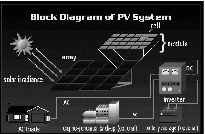
2.1 Solar cell, module and arrays 9
2.2 Illustration of “Doping Process” 12
2.3 Anti-reflective coating in Solar Cell 13
2.4 Multiple Layers in Solar Cells 14
2.5 Characteristic of Solar Panel 16
2.6 Solar Irradiance 17
2.7 Stepper Motor 18
2.8 Variable Reluctance core 20
2.9 Permanent Magnet core 21
2.10 Hybrid core 22
2.11 Magnetic flux path through a two-pole stepper motor with a lag
xv
2.12 Control Circuit Block Diagram 24
2.13 Alkaline Battery 28
2.14 Lead-acid Battery 29
2.15 Voltage Regulator Circuit Diagram 31
2.16 Battery Charger Circuit Diagram 33
2.17 UCN5804B Pinout 35
2.18 UCN5804B Structure 36
2.19 UCN5804B Internal Block Diagram 36
2.20 LM555 Pinout 37
2.21 LM555 Internal Block Diagram 37
3.1 Components assembly process 41
3.2 Soldering process 41
3.3 Troubleshooting process 42
4.1 Controlling Circuit 46
4.2 Tracking Component 46
4.3 Overall System 47
4.4 Output Voltage versus Time 1 49
xvi
LIST OF SHORT FORM
PV - Photovoltaic DC - Direct Current AC - Alternate Current PPT - Peak Power Tracker VR - Variable-Reluctance PM - Permanent Magnet
HB - Hybrid
xvii
LIST OF APPENDIX
NO TITLE PAGES
A A New Peak Power Tracker for Cost-Effective Photovoltaic 55 Power System
1
CHAPTER 1
INTRODUCTION
2
1.1 Background
In recent years, attention toward natural energy resources such as solar and wind power has increased as concern about energy security as well as the environment pollution and disruption is very much emphasized. Solar energy is inexhaustible, clean, and easy to use, directing a lot of efforts on solar power generation as the most practical and reliable source. But solar arrays are still very expensive and and take in a lot of space. In the interest of efficiency, the energy from a solar array should be maximized under all conditions.
In most photovoltaic applications, the solar panels are connected directly to the battery for charging, but these results in certain inefficiencies. Solar panels used in 12-volt applications, have very distinct power curves (12-volts x amps = watts). A graph of voltage vs. current will range from maximum current at zero volts (no power) to maximum volts at zero current (also no power). Somewhere in the middle there will be the Maximum or Peak Power Point (MPP) where the maximum output wattage can be extracted from the solar panel. Solar arrays are the most expensive components in photovoltaic power systems. Thus solar array should be operated at the maximum power point in order to reduce overall cost of the system
3
4
1.2 Project Objectives
There are three main objectives that have set out to achieve at the end of this project. They are:
a) To study the inefficiency problems encountered in most photovoltaic systems. b) To design a solar peak power tracker (PPT) which can extract the maximum
power output from the solar arrays in order to solve the efficiency problems in the circuit.
[image:21.612.198.461.326.563.2]c) To study the charge controller circuit and its application
5
1.3 Problem Statement
In applications where photovoltaic arrays are used to provide energy, maximum power trackers are used to correct for the variations in the current-voltage characteristics of the solar cells. As shown in the typical silicon cell I-V curve, as the output potential of the string rises, the string will produce significantly less current. The current-voltage curve will move and deform depending upon temperature, illumination, and consistency of cell quality in the string. For the array to be able to put out the maximum possible amount of power, either the operating voltage or current needs to be carefully controlled.
This is called maximum power point which is located at the same voltage the main system is operating at, and even if the two were equal initially, the power point would quickly move as lighting conditions and temperature change. Hence, a device is needed that finds the maximum power point and converts that voltage to a voltage equal to the system voltage.
6
1.4 Scope of Works
There are several areas that have to be identified or considered that need to be work out. There are:
a) The tracking control system
The solar panel will be designed with tracking control system. A stepper motor is the main part of this section and it will be driven by a programmed control circuit using UCN5804B BiMOS chip.
b) Types of charge controllers
There are a few types of charge controllers for solar energy conversions. Because of that, the controller should be the right one and it is suitable for the solar panel.
c) Application
7
1.5 Methodology
There are 4 phases involved in order to achieve the objective of this project. There are: a) Project Planning
b) Literature Review c) Hardware Construction d) Finishing