ELECTRONIC THROTTLE BODY TUNING USING MODEL REFERENCE ADAPTIVE CONTROL PID
AMIRUL ARIEF BIN SAIDON
ELECTRONIC THROTTLE BODY TUNING USING MODEL REFERENCE ADAPTIVE CONTROL PID
AMIRUL ARIEF BIN SAIDON
This report is submitted
in fulfillment of the requirement for the degree of Bachelor of Mechanical Engineering (Automotive)
Faculty of Mechanical Engineering
UNIVERSITI TEKNIKAL MALAYSIA MELAKA
i
DECLARATION
I declare that this project report entitled “Electronic Throttle Body Tuning Using Model Reference Adaptive Control PID” is the result of my own work except as cited in the references
ii APPROVAL
I hereby declare that I have read this project report and in my opinion this report is sufficient in terms of scope and quality for the award of the degree of Bachelor of Mechanical Engineering (Automotive).
iii
DEDICATION
iv ABSTRACT
v ABSTRAK
vi
ACKNOWLEDGEMENT
First of all, I am very grateful to meet Allah with His Grace I manage to complete my Final Year Project and the report.
I wish to express my sincere appreciation and thanks to my supervisor, Encik Faizul Akmar Bin Abdul Kadir for his valuable advice, effort and guidance throughout this project. His suggestion and patience always inspire me to produce a better work. Without him, I will never finish this project in time.
Apart from that, I also would like to take this opportunity to express my appreciation and thanks to MathWorks for developing the Mathlab/Simulink software so that I can use it in my project. This software has help me in solving the problem regarding to the project.
Not forgetting, it is an honour to work with my course mates and friends during this two semester for completing this final year project. Their ideas and support have driven me to produce a better works. Without their help, I would encounter many problems while throughout the whole project.
Finally, deepest thanks to my family for their support and care in making this research project.
vii
TABLE OF CONTENT
CONTENT PAGE
DECLARATION i
APPROVAL ii
DEDICATION iii
ABSTRACT iv
ABSTRAK v
ACKNOWLEDGMENT vi
TABLE OF CONTENT vii
LIST OF FIGURE ix
LIST OF TABLE xi
LIST OF ABBREVIATION xii
CHAPTER 1 : INTRODUCTION
1.1 Background Of Study 1
1.2 Problem Statement 4
1.3 Aim and Objective 4
1.4 Scope of Project 5
1.5 Thesis Outline 5
CHAPTER 2 : LITERATURE REVIEW
2.1 Introduction 7
2.2 Throttle Body 7
2.3 Gear Backlash 9
2.4 Mathematical Modelling 10
2.5 PID Controller 10
2.6 Fuzzy Controller 13
2.7 Cohen-Coon Method (C-C) 14
2.8 Sensitivity Analysis 15
2.9 Model Reference Adaptive Control (MRAC) 15
viii CHAPTER 3: METHODOLOGY
3.1 Introduction 19
3.2 Project Flowchart 20
3.3 ETB Model Development 21
3.4 Modelling the Electronic Throttle Body 23
3.5 Manual Tuning of PID for Electronic Throttle Body 28
3.6 Designing the Model References Adaptive Control PID 34
3.7 Summary 41
CHAPTER 4: RESULT AND DISCUSSION
4.1 Introduction 42
4.2 Throttle Opening Angle of 30 Degrees 42
4.3 Throttle Opening Angle of 45 Degrees 44
4.4 Throttle Opening Angle of 60 Degrees 45
4.5 Throttle Opening Angle of 75 Degrees 47
4.6 Throttle Opening Angle of 90 Degrees 48
CHAPTER 5: CONCLUSION AND SUGGESTION
5.1 Conclusion 50
5.2 Suggestion 51
REFERENCE 52
ix
LIST OF FIGURE
NO TITLE PAGE
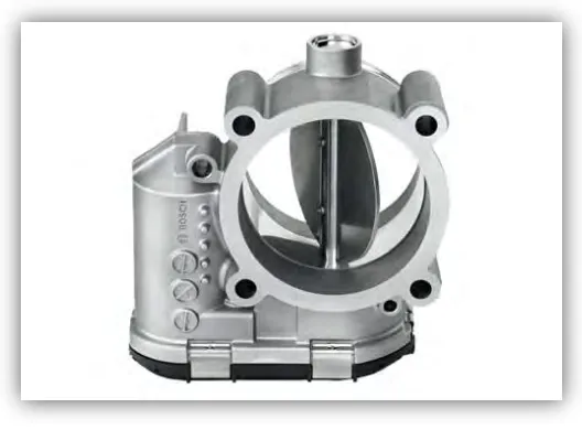
1 Throttle Body 2
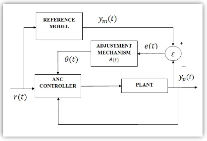
2 The Block Diagram Of The Model References Adaptive Control 3
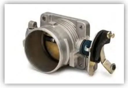
3 Throttle Body 7
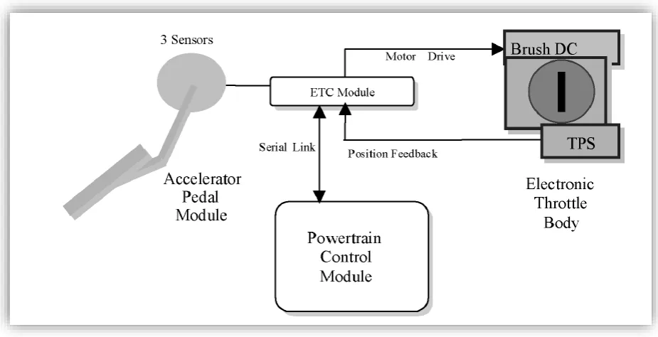
4 Electronic Throttle Body schematic diagram 8
5 The Backlash of the gear 9
6 The PID controller in Matlab Simulink 11
7 The structure of fuzzy controller 13
8 The architecture of fuzzy controller 13
9 The general Structure of MRAC 16
10(a) The cruise control button 17
10(b) The cruise control light indication 17
11 The Project flowchart. 20
12 The interface of Matlab Software 24
13 The Simulink start page 24
14 Simulink interface 25
15 Simulink library browser 25
16 ETB plant model 26
17 The ETB model with PID controller 27
18 The graph of desire throttle opening angle and the output of the throttle 28
opening angle
19 The block parameter of desire input (theta_D) 29
20 The block parameter of PID Controller 30
21 The graph of initial condition 30
22(a) The graph of the response of throttle when p is change. 31
22(b) Close up from figure 22(a). 31
23(a) The graph of the response of throttle when i is change. 32
23(b) Close up from figure 23(a). 32
24(a) The graph of the response of throttle when D is change. 33
24(b) Close up from figure 24(a). 33
25 The system identification toolbox window 36
26 The import data window 36
x
28 The transfer function block and gains block in Simulink 38
29 The model of equation (28) 38
30 The model of equation (29) 39
31 The model of equation (30) 39
32 Sum of the three products 40
33 The comparison between the throttle angle for 30 degrees 42
34 The zoom in the red circle in figure 34 43
35 The comparison between the throttle angle for 45 degrees 43
36 The zoom in red circle in figure 36 43
37 The comparison between the throttle angle for 60 degrees 45
38 The zoom in red circle in figure 38 46
39 The comparison between the throttle angle for 75 degrees 47
40 The zoom in red circle in figure 40 47
41 The comparison between the throttle angle for 90 degrees 48
xi
LIST OF TABLE
NO TITLE PAGE
1 The Effect Of Each Controller On A Close-Loop System 12
2 The parameter value for the simplified model 23
xii
LIST OF ABBREVIATION
EEV Earth Efficiency Vehicles
ETB Electronic Throttle Body
PID Proportional Integral Derivative
1 CHAPTER 1
INTRODUCTION
1.1 Background Study
During this area of globalization, the automotive sector has been one of the major contributor to the nation income. With Proton and Perodua lining up our local automotive manufacturer with some other global manufacturer such Toyota, Honda, Ford and BMW, our automotive sector look quite promising in the next few years. Nowadays, all of the car manufacturer are targeting to build an earth efficiency vehicle (EEV) that can improve the driveability, fuel economy and the emission of the vehicle (Pavković et al. 2006). One way to achieve these is by using the Electronic Throttle.
2
Figure 1: The Throttle Body.
Besides that, the Electronic Throttle Body also can perform as a mechanism that improve significantly the engine and vehicles performance. There is a research that shows the driver can choose the powertrain responsiveness to match his or her desire (Mckay et al. 2000). By choose a certain mode, the electronic throttle body or control will adjust the gain or sensitivity of the accelerator pedal in response to the driver input selection. To choose the mode, the driver only need to push a certain button and the rest will be up to electronic throttle control to fulfil those requirements such as the driving condition and the driver mood. Lately, there are three kinds of that is available at the market which are normal mode, power mode and winter mode. There is still more mode to add to the vehicle but those three mode are currently commonly being used.
3
[image:17.595.97.515.284.569.2]For Model Reference Adaptive Control(MRAC), it is a control system that make the plant to be as close as possible to the model references. The input or the control parameter of the plant are being adjusted automatically for time to time(R. Isermann, K.-H. Lachmann and Matko 1992). As the parameter of the plant continuously being change, the output of the system will be based on the desired response that have being set for the references model. The existence of the MRAC controller will compensate the disturbance that have been create by the nonlinearities of the Electronic Throttle Body. Adaptive control also very good at tracking the performance of the system.
4 1.2 Problem Statement
Electronic throttle body is one of essential part that needs in current vehicles so that it can adjust the ratio between the air and fuel that enter the combustion chamber. The problem is that the electric throttle body have some non-linearity such as stick-flip friction, backlash that occurs between the gear and the discontinuous nonlinear of the spring that use to return the valve plate to its initial position. This non-linearity causes the disturbance that can affect the performance of the electronic throttle body.
So, in order to overcome this problem, a proper controller will be needed to compensate the disturbance by the non-linearity. The propose controller that will be used in this project is Model References Adaptive Control (MRAC) PID. To apply the controller, a model of Electronic Throttle Body will be model by using Matlab/SIMULINK. Then, MRAC will be applied in the ETB model.
1.3 Aim and Objective
The aim of this research project is to tuning the Electronic Throttle Body using Model References Adaptive Control PID
The aim and the research objective of the thesis are:
To develop an Electronic Throttle Body(ETB) model in Matlab Simulink.
To apply Model Reference Adaptive Control PID controller to obtain the desired throttle angle.
5 1.4 Scope of Project
The scope of this project are:
1. Study about the throttle body on how to control the disturbance created by the non-linearity of the system.
2. This project only focus on simulation only.
3. The simulation will be perform using Matlab (Simulink) software. 4. Model the ETB provide by (Pan et al. 2008) by using matlab/simulink 5. Apply the Model reference adaptive control PID to the ETB model. 6. Compare the result for conventional PID with MRAC PID.
7. Do various simulation for different throttle opening angle such as 30o, 45o, 60o, 75o and 90o.
1.5 Thesis Outline
The First chapter is an introduction part which discusses briefly on the background, problem statement, aim and objective of the project. Besides that, this chapter will briefly mention about the outline of the project.
Chapter Two will discuss about the literature review. All the concept and operation that related to the Electronic Throttle Body will be discus. The study about the controller and the method of the control will be discus.
Next, chapter Three will discuss about the method used to carry out this project. The steps to complete this project also will be discussed in this chapter, including the tuning method and the simulation. The step to model the plant and the controller also being discuss in this chapter.
6
7 CHAPTER 2
LITERATURE REVIEW
2.1 Introduction
This chapter reviews the relevant literature review in application related to research of electronic throttle body, type of controller, type of manual tuning method, automatic tuning method and modelling
2.2 Throttle Body
[image:21.595.193.415.572.724.2]For every vehicle, to control the speed either to increase the speed or to decrease it is very importing characteristic that should be include in the vehicles. One way to control the speed is by controlling the air fuel ratio that enter the combustion chamber. So, throttle body is the one who control the ratio. The throttle body works by adjusting the valve plate that place inside the throttle body(Pan et al. 2008). When the acceleration pedal is pushed, a mechanical linkage that link the pedal and the valve plate will pull a spring that open the throttle angle(Panzani et al. 2011)(Rossi et al. 2000). As the valve is open, it will allow the air and fuel to enter the combustion chamber.
8
[image:22.595.93.556.304.541.2]With now advance technology, the mechanical linkage now not directly connected to the gas pedal anymore. The existence of the Electronic Throttle Body (ETB) is widely used in modern car now days. It is because of the reliability of the throttle body itself. For ETB, the gas pedal not connected to the throttle body but to the sensor. The sensor will sense the position of the gas pedal and will send the Engine Control Unit (ECU)(Mckay et al. 2000). The function of ETU is to determine the opening angle of the valve. By taking others input parameter from the engine such as the slop of the road, road condition, and the driver behaviour, the control unit will determine the best opening angle of the valve. The advantage of using ETB is the fuel efficiency, a comfortable drive experience, and less emission.
9 2.3 Gear Backlash
[image:23.595.160.448.272.440.2]One of the problem that occurs in Throttle Body is that there is lies the backlash of the gear that need to turn the valve plate. The existence of the gearing backlash has cause the disturbance of the Throttle body system and may have affected its performance. Gear backlash exist because of the gap between the gear tooth(Engineering 1996). These phenomena are common in servomechanism especially in mechanical system that involve the gear-driven system.
Figure 5: The backlash of the gear.
10 2.4 Mathematical Modelling
Modelling is the process of identifying the physical dynamic effects to be considered in analysing the system. The modelling can involve many mathematical equation such as ordinary differential equation (ODEs), partial differential equations (PDEs), differential algebraic equations (DAEs) and ODEs interfaced with discrete-time algorithms (DTAs)(Taylor 2001). The purpose of the mathematical modelling is to predict the response of the system before applied into the real system. Actually this project is about modelling a nonlinear system. A nonlinear system is a system in which the output of the system is vary within the time and not directly proportional to the input (Heij & van Schagen 2007). The performance of the Electronic Throttle Body will depend on the efficiency of the control system and the dynamic model of the system. The mathematical modelling of the Electronic Throttle body will be discussed in Chapter 3.