DEVELOPMENT OF AN AUTOMATED COOLANT SYSTEM FOR
CNC MACHINE
This report submitted in accordance with requirement of the University Teknikal Malaysia Melaka (UTeM) for the Bachelor Degree of Manufacturing Engineering
(Robotic and Automation)(Hons.)
by
CHEE KAI SIN B051310146 931210-01-5506
i
ABSTRAK
ii
ABSTRACT
iii
DEDICATION
iv
ACKNOWLEDGEMENT
First and foremost, I would like to grab this golden opportunity to show my greatest appreciation to my respected supervisor, Dr Fairul Azni bin Jafar for the best mentoring and guiding that was given throughout the whole project. He has given me a bundle of useful and valuable assistances especially in the project development progress.
Besides that, my fervent thanks to all my beloved family members and friends who has always show their fully support and gave me much cooperation mentally and motivation in completing this project. They are always been there whenever I need them the most.
v
TABLE OF CONTENT
ABSTRAK i
ABSTRACT ii
DEDICATION iii
ACKNOWLEDGEMENT iv
TABLE OF CONTENTS v
LIST OF TABLES viii
LIST OF FIGURES ix
LIST OF ABBREVIATIONS xi
LIST OF SYMBOLS xii
CHAPTER 1 INTRODUCTION 1
1.1 Background 1
1.2 Motivation 4
1.3 Problem Statement 5
1.4 Objective 5
1.5 Scope 5
1.6 Report Structure 6
Chapter 2 LITERATURE REVIEW 8
2.1 Computer Numerical Control (CNC) Machine 8
2.2 Coolant Supply System (Cooling techniques) 10
2.2.1 Dry Machining Cooling Techniques 10
2.2.2 High Pressure Cooling Techniques 12
2.2.3 Mist Cooling Techniques 14
2.2.4 Wet Cooling Technique 15
2.2.5 Minimal Quantity Lubrication Techniques (MQL) 16
2.3 Comparisons of MQL and other cooling systems 20
2.4 Automated Supply System 21
2.4.1 Arduino Microcontroller 22
vi
2.5 Summary 26
CHAPTER 3 METHODOLOGY 27
3.1 Introduction 27
3.2 Overall Methodology 28
3.3 Problem Statement 29
3.4 Literature Review 29
3.5 Process Planning 29
3.5.1 Bill of Material (BOM) 31
3.5.1.1 Programmable Logic Circuit 31
3.5.1.2 Nozzle 33
3.5.1.3 Inlet Valve 34
3.5.1.4 Ladder Diagram 35
3.6 Detail Design 35
3.7 Development 36
3.7.1 Software Development 37
3.7.1.1 Ladder Logic 39
3.7.1.2 Ladder Diagram 39
3.7.2 Hardware Development 40
3.8 Analysis 41
3.8.1 Experimental Setup 41
3.8.2 Experiment Procedure 41
3.8.2.1 Test performance of unloaded coolants 42
3.8.2.2 Performance Analysis 42
3.8.2.3 Tester 43
3.9 Expected Results 44
3.10 Summary 45
CHAPTER 4 RESULT AND DISCUSSION 46
4.1 Software Development 46
4.1.1 Ladder Diagram 48
4.1.2 Preliminary Test 50
4.1.2.1 Communication with PLC 50
4.2 Hardware Development 51
4.2.1 Electrical Part 52
4.2.2 Mechanical Part 52
4.2.3 Unloaded Testing 54
4.2.4 Loaded Testing 55
4.2.5 Experimental Result 57
4.2.6 Result Analysis 60
4.3 Summary 63
CHAPTER 5 CONCLUSION AND FUTURE WORKS 64
5.1 Conclusion 64
5.2 Future Works 66
REFERENCES 67
APPENDICES 71
A Project Gantt Chart for FYP 71 B Roughness Reading For Test 1 71 C Roughness Reading For Test 2 71 D Roughness Reading For Test 3 71
viii
LIST OF TABLES
2.1 Balance of positive and negative impacts in dry machining 10
3.1 Results obtained from the experiments 43
4.1 Condition menu set at roughness tester 56
ix
LIST OF FIGURES
2.1 Dry Machining 11
2..2 High Pressure Cooling Techniques 12
2.3 Mist Cooling Technique 14
2.4 Wet Cooling Techniques 15
2.5 Minimal Quantity Lubrication 16
2.6 Image of MQL nozzle positioning during turning process 17 2.7 Temperature gradient dissemination for dry drilling (left) and MQL (right) 19
2.8 Arduino Uno 22
3.1 The overall methodology of the project 27
3.2 Word break down structure diagram for problem statement 28
3.3 Flowchart in planning process 29
3.4 Bill of material 30
3.5 Programmable Logic Controller, Omron CP1E 31
3.6 Specification of Omron CP1E PLC 32
3.7 CNC lathe machine plastic nozzle 33
3.8 Proportional flow control valve 33
3.9 Flowchart of detail design 34
3.10 Detailed design of automated coolant system 35
3.11 Actual position of Automated coolant systems’ valve in CNC machine
35
3.12 Flowchart of development process 36
3.13 Flowchart for software development process 37
3.14 Flowchart for hardware development process 39
3.15 Roughness tester 42
3.16 Surface roughness trend of automated coolant system 44
4.1 Work flow of the PLC system construction 46
4.2 Flowchart of development of ladder diagram 47
4.3 Ladder diagram schematic in CX-Programmer software 48
4.4 Results when the start button is switched on 49
x
4.6 Electrical and wiring part of the system 51
4.7 SOLIDWORKS image of piping 52
4.8 Connection of the mechanical part of the hardware 53
4.9 Image of mechanical part on CNC machine 53
4.10 Coolants from the nozzle are precisely dispersed to the tooling 54 4.11 Commands is sent to stop the coolants from dispersed onto the tool 54 4.12 At the 0.00 period, the coolants start dispersed from the nozzle 55
4.13 The coolants stop dispersed at 5s sharp 55
4.14 Milling process is undergone on the aluminium block 56 4.15 Graph plotted regarding to the data from experiment 1 57 4.16 Graph plotted regarding to the data from experiment 2 58 4.17 Graph plotted regarding to the data from experiment 3 58 4.18 Graph plotted regarding to the data from the overall experiments 59 4.19 (a) shows the new tool and (b) shows the difference colour tone at tool bit
indicates that the tool is dull 61
4.20 (a) shows the new tool and (b) shows the scratch on the tool. 61 4.21 (a) shows the new tool and (b) shows some scratches on the surface of the
xi
LIST OF ABBREVIATIONS
CNC - Computer Numerical Control
PLC - Programmable Logic Circuit
TCA - Trichloroacetic Acid
MQL - Minimal Quantity Lubrication
AL - Aluminium
AISI - American Iron and Steel Institute
CAD - Computer Aided Design
CAM - Computer Aided Manufacturing
G-code - Preparatory Code
FEM - Finite Element Method
NDG - Near Dry Grinding
LED - Light Emitted Diode
USB - Universal Serial Bus
PC - Personal Computer
I/O - Input and output
ICS - Intelligent Cooling System
DC - Direct Current
AC - Alternating Current
VDC - Volt of Direct Current
CPU - Central Processing Unit
2D - 2-Dimensional
NOTC - Normally-open, Timed-closed
NOTO - Normally-open, Timed-opened
xii
LIST OF SYMBOLS
% - Percent
MPa - Mega Pascal
Km/h - Kilo meter per hour
L/min - Litre per minute
ml/min - Millilitre per minute
℃ - Degree Celcius
ml/h - Millilitre per hour
mm/s - Millimetre per second
rpm - Revolution per minute
mm - Millimetre
1
CHAPTER 1
INTRODUCTION
In this chapter, overview of Computer Numerical Control (CNC) machines, which includes the cleaner application techniques and the method to apply coolants (Arduino and Programmable Logic Circuit (PLC)) in machining is discussed. Next, the inspiration of using PLC to replace the conventional method is discussed in the motivation part. The problem statement, objectives, scopes and report structures are also discussed.
1.1 Background
In current manufacturing industry, the seeking of low prising, high efficiency as well as great quality of product are rising. However, high machining speed, small amount of feed rate and large cut depth is directly linked to a high productivity and which will unswervingly cause the heat generation in profusion and high cutting temperature in the machining region. The overheating of the tooling may diminish its incisiveness and accuracy. Also, using unsharpened cutter will eventually lead to extremely high power usage and poor surface finishing. Thus, faster tool wear, low quality machining and low surface integrity of the product is formed. Therefore, cutting oil is needed in machining in order to make the workpiece cool, diminish friction, and rinse away the chips. Vieira et al. (2001) stated that
cutting fluids plays an ultimately important role in machining process with the intention of rising the productivity. When the cutting fluid is applied, the quality of the machined surface is able to be enhanced and the tool wear is diminished. Also, the cutting forces is minimized and therefore the energy is saved.
2
oil is mineral-based cutting fluid which is widely used around the world. However, this mineral-based cutting fluid has strong negative impacts to health and environment. Shashidhara & Jayaram (2010) stated that approximately 80% of all work-related contagions of the workers were because of close skin interaction of operator with cutting fluids. Besides that, greatly use of poisonous and less biodegradability cutting fluids can cause severe health problems like respiratory infections, lung cancer, dermatological as well as inherent diseases and also numerous techno-environmental problems (Ozcelik et al., 2011).
Moreover, Klocke and Kuchle (2011) said that a special incineration sites is purposely made in order to burn cutting fluid which containing of chlorinate. This is because that the toxic components in the cutting fluid can cause uncontrolled burning. Thus, it is categorised as a risky and dangerous waste to biological life and environment. Salate et al.
(2008) defined that the discarding of cutting fluids will result in an upsurge of carbon dioxide releases to the surrounding and as a result of global warming occurrence. Besides that, chemical Trichloroacetic Acid (TCA) in cutting fluids is associated with high-level ozone depletion.
Since all the three aspects i.e. health, environment and economy had been seriously affected from the use of coolant fluids, there are methods of application of cutting fluids in CNC machine that were investigated in order to obtain the optimal method of application. The investigation includes the comparisons of dry machining, conventional flood lubrication (wet cooling), and minimal quantity lubrication (MQL) regarding to the tool wear, surface roughness, temperature deviation with the alteration in depth of cut and amount of coolant used.
a) Dry Machining
3
and workpiece can lead to obviously upsurge of the temperature and eventually results in higher standard of oxidation, abrasion and diffusion. Moreover, Diniz and Micaroni found that the excessive heat occurring in the workpiece will consequently impede the achievement of tight tolerances and metallurgical damage. Hence, in such circumstance, dry machining is considered neither practical nor commercial.
b) Conventional Flood Lubrication (Wet Cooling)
Flood lubrication is the most common application method used in CNC machine. This method delivers a stable flow of fluid to the workpiece or tool chip interface for machining operation (Groover 2002). Imran et al. (2013) revealed that using
conventional flood lubrication will result in a large degree of surface deformations with high dislocation density in nanocrystalline grain structures. Also, Imran et al. concluded
that the key wear mechanism for flood cutting were diffusion, abrasion and micro- chipping. In additional, there is an abundant waste of cutting fluids which lead to a high production costs.
c) Minimal Quantity Lubrication (MQL)
Jayal et al. (2009) defined that MQL is an environmentally friendly and economically
beneficial method. In MQL technique, aerosol concept which is mixing a very small quantity of cutting fluids and air had been used and the mixture is sprayed in the cutting zone with the use of nozzle (Varadharajan et al., 1999). The major advantages of MQL
are decreasing in cutting fluids consumption, reducing cost, decline of negative influence to the environment, as well as enhanced overall performances in machining operation and apparent quality (Fratila, 2009). Furthermore, several researches had been done to prove that MQL provides better performance than dry and wet machining. Li & Lin (2012) explored that MQL is able to dramatically reduce the surface roughness, improve tool lifespan and burr development. Heinemann et al. (2006) noticed that with
4
With the comparison of the three application methods, the concept of MQL application has been chosen to be the basis of this research work. This is because of its vast benefits in enhancing machining performance, reducing the cost related with the removal of used oil and also minimizing the machine-tool cleaning cycle time and energy usage. Elahi
et al. (2015) had proposed a research named Intelligent Cooling System (ICS) for machining.
This system applied MQL method and used integrated Arduino micro-controller in controlling the amount of coolant used. In this system, temperature sensors are used in detecting the cutting zone temperature and once the temperature of the work piece had reached a fixed temperature, the integrated Arduino micro-controller then open the solenoid valve to supply the fluids as a continuous supply for a limited time until the temperature is reduced back. From this research work, an idea on using time-based supply coolant with the help of PLC is inspired.
The goal of this research work is to develop an automated coolant supply system with the help of Programmable Logic Circuit (PLC) to control the amount and the timing of the coolant needed. By using this technique, it is expected that almost similar product quality can be produced, tool wear lifetime is reduced, and more environmental friendly condition can be achieved as regards to current conventional flood cooling technique.
1.2 Motivation
5
1.3 Problem Statement
Currently, most of the conventional CNC machines are using flood cooling method in order to reduce friction between workpiece and tooling, to remove the heat of the workpiece and also rinse away the chips. However there are three major problems exist with the used of wet cooling method and consequently bring result to the development of PLC control based coolant supply (time-based supply). That is with the use of excessive coolant in an extended period, health and environment will be severely affected. Also, the flood cooling method supply a large amount of coolants to cool down the workpiece, however there is only 10% to 15% of the coolant that able to play their role in cooling the workpiece while the rest of the coolants are just wasted. This has caused the increase in waste and production cost. Moreover, machine-tool cleaning cycle time is long and finally leads to a waste of manpower. Thus, in order to minimize the usage of coolants, reduce the production cost, and shorten the machine-tool cleaning cycle time, a PLC control based coolant supply is proposed to eliminate these problems.
1.4 Objective
The objective of this project are:
i. To develop an automated coolant supply system with the used of PLC to control the amount supply and timing of the coolant.
ii. To analyse the performance of the developed system.
1.5 Scope
The scope work of this project are:
i. The system will be operated by using Keyence Programmable Logic Circuit (PLC) ii. 10mm high speed steel tooling is in used.
iii. Several fixed variables will be set such as 250mm/s feed rate, 1500rpm of spindle speed and 0.5mm depth of cut are in used. These variables are determined by Das
6
iv. The cutting fluid used is Al Soluble Extra and other types of cutting fluid will not be considered.
v. Workpiece will be AISI 304L only, other type of workpiece material will not be considered. .
1.6 Report Organisation
This report consists of five key chapters which are introduction, literature review, methodology, discussion and conclusion. Some short reviews are discussed in subsequent chapters. First of all, chapter 1 is discussed about the introduction of the whole report. In chapter 1, background of the project, the motivation, objectives, problem statement and scope of study will be covered.
Chapter 2, Literature Review involves of a lot of researches and findings that related to the CNC machine, types of coolants supply and automated supply system will be discussed. Comparisons between five types of cooling techniques had been undergone and the best cooling technique which is MQL has been selected to proceed the project. Also, the benefits and the applications of Arduino microcontroller and PLC had been further discussed.
Next, chapter 3, Methodology shows various types of methods that are used to fulfil and succeed the objective and scope of the project. Project flow is discussed thoroughly with the used of flow chart. Bill of materials had been listed out and each materials in use is discussed. Also, experiment procedure to examine the performance had been covered.
Chapter 4 contains the software and hardware development. For the software development, details of ladder diagram are discussed over while for the hardware development, the specific particulars about the connection of electrical and mechanical parts are covered. Unloaded and loaded testing are undergone in order to analyse the performance of the system.
7
Chapter 2
LITERATURE REVIEW
This chapter describes about the details of the research works that had been previously done. In this chapter, history of CNC machine, type of coolant system, and control of automated coolant system will be described thoroughly and the information obtained will become the guideline to proceed and succeed this project.
2.1 Computer Numerical Control (CNC) Machine
CNC machine consists of a mini computer or a microcomputer which performs as the controller unit of the machine. The computer and prepared program of coded alphanumeric data in the machine are used to control, automate as well as monitor the motions and movements of the workpiece or tool. CNC machine also capable in inserting different parameters for example depth of cut, feed rate, speed and also tuning on/off the spindle as well as the functions of cutting fluids on/off. The advantages of CNC machines are:
• Able to perform constant repetitive tasks
• High precision and accuracy in machining process • Short machining time
• Better manufacturing flexibility and minimized human errors
8
dimensional drawing and drafting in the early stage. Requicha (1980) stated that the solid modelling emerged to describe three-dimensional products and it has been seen an increase using of solid modellers and three-dimensional CAD systems. Besides that Computer Aided Manufacturing (CAM) has been introduced to manufacture the products. However, there is very little or no linkage and communication between the CAD and CAM (Han, 1996).
Next, computers were known to a manufacturing sector in order to compute and regulate the cutter movements of machine tools however this requires a lot of mastery skills in identifying and interpreting the shape details from engineering drawings. Therefore, a special languages which are able to translate the drawing details into the computer-controlled machine tool were developed (Mortenson, 1985). The CNC machine is programmed by G-code (ISO 6983) which the cutting tool movement is largely altered and moved in terms of the feed rates of axes and position (Taylor et al., 2010).
G-code, also known as preparatory code is a well-accepted standard in worldwide. This is a language which guided the machine tools on the path to move, the destination of the tooling, the spindle speed, the feed rates as well as the X, Y, Z for axis motion. Besides that, it is written in sentence-like format and all the programs will be executed and performed by control in step- by-step, successive order. Hence, a distinctive sequence of CNC words are make-up as commands in order to interconnect what the machine is planned to move. Below indicates the types of actions that are able to be performed by the control of G-codes:
• Rapid movement (transport the tool to the set location in very fast pace) • Controlled feed in a straight line or arc
• Set tool information such as offset, feed rate, spindle speed and etc.
9
the toolchip contact point, as well as the overheating of the tooling is the crucial adverse factor in affecting the quality of products and as a result in decreasing the productivity.
Vieira et al. (2001) revealed that cutting fluids plays an ultimately vital role in
machining process with the intention of rising the efficiency and productivity. With the application of cutting fluids, heat generation in machining is significantly reduced, distortion of the work piece is minimized and thus the surface roughness is dramatically improved. Davim
et al. (2007) stated that surface quality is directly linked to the evaluation of productivity of
machine tools and mechanical parts. Therefore, cutting fluids is crucially important in machining process. Moreover, there are three types of coolants supply system that help in increasing productivity and decreasing the heat generation. Details of these three different types of coolant system will be discussed in next session.
2.2 Coolant Supply System (Cooling techniques)
The heat and friction produced in machining will result in bringing a deleterious effect to cutter and superficial layer of the work pieces. Therefore, with the use of coolant, a slight decline in temperature between cutter and work material is able to be achieved and in results of extensively enhances the cutter lifespan and surface finish. The characteristics of the cooling techniques at the cutting zone must be clearly understood so that the heat produced in machining can be reduced successfully and it may result in an effective and economic machining. Sharma et al. (2009) stated that numerous cooling techniques had been introduced
to control the temperature at the cutting zone and in result of productivity is upgraded and the general effectiveness of the process is amplified.
2.2.1Dry Machining Cooling Techniques
10
contamination of water resources, air or atmosphere, no occupational danger to health and significant cost reduction as there is no maintenance and disposal cost (Sreejith & Ngoi, 2000). Groover (2010) claimed that dry machining is desirable and optimum when working at lower cutting speed. This resulted in low production rate is formed and tool lifespan is able to be lengthen. Moreover, Sreejith et al. (2000) defined that the dry machining is become more
[image:23.596.55.510.243.366.2]widely used because of the lower cost and reduce undesirable influence to the atmosphere, ecosystem and well-being problems in the shop floor.
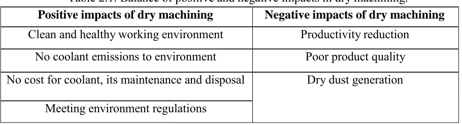
Table 2.1: Balance of positive and negative impacts in dry machining.
Positive impacts of dry machining Negative impacts of dry machining
Clean and healthy working environment Productivity reduction No coolant emissions to environment Poor product quality No cost for coolant, its maintenance and disposal Dry dust generation
Meeting environment regulations
However, problems like overheating between the tool and workpiece is largely happened. The high friction occurred in dry cutting condition will directly obviously upsurge the temperature and causing in high level of diffusion, abrasion and oxidation. Also, high friction results in dry machining will lead to high tool wear and built-up edge formation, which affects machined surface finish. Hence, due to the maintaining of the great surface quality, the feed rate and speed had to slow down and this directly decline the productivity and rises the production cost. Moreover, the large amount of heat will obstruct the tight tolerances achievement and occur the metallurgical destruction to the surface layer of workpiece (Diniz, 2003). Furthermore, the worsening on the machined superficial layer due to the chip formation, is unable to be washed away. Therefore, Alves et al. (2008) explored that eliminating coolants
11
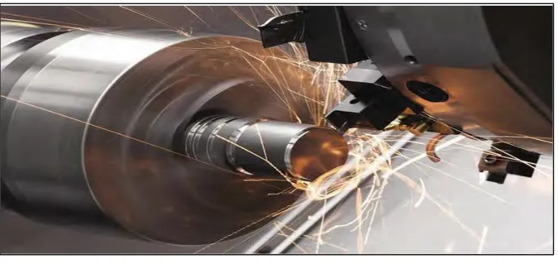
Figure 2.1: Dry Machining.
(Source: https://www.ctemag.com/news-videos/articles/coolgroove)
As a result, Braga et al. (2002) had conducted an experiment to find out the most
suitable cutting condition for dry cutting by not affecting the surface roughness of workpiece, obtaining suitable cutting power, and a longer tool life. The experiment is carried out with the used of coated carbide inserts in steel turning process. From the experiment, dry cutting will result in smaller surface roughness. This is due to the dry cutting will affect the temperature of the work materials close to the cutting region and directly result in declining of the hardness and strength. This consequences in the formation of chips become much easier, the cutting force is decreased and therefore the roughness is decreased. The higher the feed rate, the greater the surface roughness. Hence, in order to make the dry cutting process more suitable to be used, the feed rate should be increased.
Moreover, dry cutting obtained a smaller cutting power. This is because the dry cutting will cause the upsurge of the workpiece temperature and consequences the hardness and strength of the workpiece decline. Hence, the decrease of the cutting power occurred. Also, the cutting power will rise when the speed is rise, however the power will be constant or even smaller when the feed is increased. Thus, Braga et al. (2002) concluded that the application of