Plasma Phys. Control. Fusion56(2014) 084001 (8pp) doi:10.1088/0741-3335/56/8/084001
Enhanced proton beam collimation in the
ultra-intense short pulse regime
J S Green
1, N P Dover
2, M Borghesi
3, C M Brenner
1,4, F H Cameron
1,
D C Carroll
1,4, P S Foster
1,3, P Gallegos
1,4, G Gregori
5, P McKenna
4,
C D Murphy
6, Z Najmudin
2, C A J Palmer
7, R Prasad
8, L Romagnani
9,
K E Quinn
3, J Schreiber
10,11, M J V Streeter
2, S Ter-Avetisyan
12, O Tresca
4,
M Zepf
3and D Neely
1,41Central Laser Facility, STFC, Rutherford Appleton Laboratory, Chilton, Didcot, OX11 0QX, UK 2Blackett Laboratory, Imperial College, London, SW7 2BZ, UK
3Department of Physics and Astronomy, Queens University, Belfast, BT7 1NN, UK 4SUPA, Department of Physics, University of Strathclyde, Glasgow, G4 0NG, UK 5Clarendon Laboratory, University of Oxford, Oxford, OX1 3PU, UK
6Nuclear Physics Group, University of Edinburgh, Edinburgh, EH9 3JZ, UK 7DESY, Notkestr. 85, Hamburg, Germany
8Institute for Laser and Plasma Physics, Heinrich Heine University, 40225 Duesseldorf, Germany 9LULI, ´Ecole Polytechnique, CNRS, CEA, UPMC, F-91128 Palaiseau, France
10Fakult¨at f¨ur Physik, LMU M¨unchen, D-85748 Garching, Germany 11Max-Planck-Institut f¨ur Quantenoptik, D-85748 Garching, Germany
12ELI–Beamlines, Institute of Physics, Czech Academy of Science, 18221 Prague, Czech Republic
E-mail:james.green@stfc.ac.uk
Received 26 November 2013, revised 3 February 2014 Accepted for publication 4 February 2014
Published 22 July 2014
Abstract
The collimation of proton beams accelerated during ultra-intense laser irradiation of thin aluminum foils was measured experimentally whilst varying laser contrast. Increasing the laser contrast using a double plasma mirror system resulted in a marked decrease in proton beam divergence (20◦to<10◦), and the enhanced collimation persisted over a wide range of target thicknesses (50 nm–6µm), with an increased flux towards thinner targets. Supported by numerical simulation, the larger beam divergence at low contrast is attributed to the presence of a significant plasma scale length on the target front surface. This alters the fast electron generation and injection into the target, affecting the resultant sheath distribution and dynamics at the rear target surface. This result demonstrates that careful control of the laser contrast will be important for future laser-driven ion applications in which control of beam divergence is crucial.
Keywords: laser, plasma, electron, acceleration, proton
(Some figures may appear in colour only in the online journal)
1. Introduction
Utilizing laser-driven ion beams as compact sources for a number of technological applications has remained a key
Content from this work may be used under the terms of theCreative Commons Attribution 3.0 licence. Any further distribution of this work must maintain attribution to the author(s) and the title of the work, journal citation and DOI.
Figure 1.(Left) Experimental set-up showing the double plasma mirror arrangement early in the beam line, used to increase the laser contrast by∼103. (Right) The proton beam spatial profile was recorded∼8 cm behind the target.
inertial confinement fusion [5]. The most thoroughly explored mechanism for laser-driven ion beams is sheath acceleration [6], in which the laser heated electrons drive plasma expansion from the target foil surface, accelerating surface ions and protons to high energies. There have been a number of recent studies on controlling the properties of the accelerated beams by implementing novel target designs, varying laser parameters or introducing post-target beam control. Recent review articles by Macchiet al[7] and Daidoet al[8] summarize relevant progress in these areas.
It is well known that the properties of laser-driven ion beams are largely determined by the parameters of the drive laser; typically intensity, pulse duration and energy. As laser intensities have increased with the advent of chirped pulse amplification (CPA) the effects of pre-pulses and amplified spontaneous emission (ASE) have become more significant. At focused intensities of 1020W cm−2nanosecond ASE pedestals can reach intensities that exceed the ionization threshold of the target, leading to the formation of pre-plasma on the target front surface. Previous investigations into the effect of laser contrast on rear surface ion acceleration have highlighted the problem of pre-heating of the target rear surface due to significant laser pre-pulse. The presence of a pre-formed plasma on the target rear surface can greatly suppress the sheath acceleration process by reducing the peak accelerating electric field [9,10]. Alternatively deformation of the target rear surface due to pre-pulse shock heating can lead to an increase in ion emission away from the target normal direction [11,12]. One key parameter for laser-driven ion beams when considering their use for applications is the beam divergence from the source. Due to their inherent large divergence, despite a high number of particles accelerated per laser shot the achievable flux decreases rapidly away from the source, presenting a severe limitation for many applications. In this paper we experimentally demonstrate an enhancement in proton beam collimation by control of the laser contrast. Aluminum foil targets were irradiated at high intensity under both low and high contrast laser conditions, the latter being achieved with the use of double plasma mirror system [13]. The angular distribution of the laser-generated proton beam was found to be highly dependent on laser contrast. In
conjunction with hydrodynamic and two-dimensional (2D) particle-in-cell (PIC) simulations we demonstrate that for the parameter range investigated, a change in the fast electron generation process due to the presence of the pre-formed plasma on the target front surface is the key factor in altering the proton beam emission profile.
2. Experimental set-up
The experiment was performed at the Rutherford Appleton Laboratory using the Astra Gemini laser which delivered up to 12 J of energy with a pulse duration of 50 fs. Anf/2 off-axis parabola was used to focus the 800 nm, p-polarized beam on target with a 2.5µm full width at half maximum (FWHM) spot diameter, yielding a peak intensity of 1021W cm−2. Approximately 35% of the laser energy was contained within the central FWHM. A fast diode was used to measure the level of ASE before the main pulse. The nanosecond intensity laser contrast (the ratio of the main pulse intensity to that of the nanosecond ASE) was found to be∼109up to 1 ns before the main pulse. For some data sets higher contrast was required so a double plasma mirror system was used to increase the contrast by a factor of∼103. This was achieved by focusing the incoming laser beam, using an off-axis parabola, onto two plasma mirrors before re-collimating and delivering the beam on to target, as shown in figure1. The combined reflectivity of the plasma mirrors was found to be 48%, resulting in a peak intensity on target of∼5×10²⁰W cm−2.
A range of Al foil targets were used, with target thicknesses ranging from 50 nm to 20µm. The targets were irradiated at 35◦to target normal. Pre-heating and distortion of the target rear surface due to ASE and pre-pulse meant that targets thinner than 6µm could only be irradiated with the addition of the double plasma mirror system. The targets were mounted in a 5×5 array on a rotating target wheel, permitting multiple data sets to be collected without breaking the vacuum of the interaction chamber.
Figure 2.Proton beam (5–8 MeV) profiles showing the lower half of the proton beam for a 6µm Al target foil under low (a) and high (b) contrast conditions. Additional profiles are also shown for both 900 nm (c) and 100 nm Al (d) target foils under high contrast conditions. 20◦full cone angles are shown for reference.
120×60 mm, 400µm thick scintillator was held in a light-proof assembly, together with an aluminized glass pellicle that was mounted at the front of the diagnostic in order to shield the scintillator from target debris and laser light. A scintillator energy observation window of 5–8 MeV was calculated using the ion stopping code SRIM [15], with lower proton energies and heavier ions being stopped by the protective pellicle. While the plastic scintillator is sensitive to a range of ionizing radiation, for the target thickness range being considered here, the scintillator signal due to electron and x-ray flux was found to be insignificant when compared to that of the proton signal. The scintillator fluorescence was collected and imaged onto a Princeton Instruments charge-coupled device (CCD) camera.
3. Experimental results
The first data set was collected under low contrast conditions, using two mirrors to bypass the plasma mirror system. Al targets were irradiated with target thicknesses of 6, 10 and 20µm. For each target foil the divergence of the proton beam (within the 5–8 MeV observation window) was calculated by measuring the horizontal FWHM of the half beam as recorded by the scintillator. This assumes a certain degree of circular symmetry for the proton beam, or an axis of symmetry in the horizontal target plane. The behaviour of the scintillator beam profile diagnostic was benchmarked using a number of full beam reference samples that were recorded using a radiochromic film stack. If a clear measurement of the beam FWHM could not be made, due to the beam being only partly visible on the scintillator, then the data was excluded from the data set. This typically occurred when the target foil was not mounted exactly parallel to the target array surface.
The full cone angle for the 5–8 MeV protons was found to range between 16◦ and 28◦ for low contrast conditions. Figure2(a) shows a typical beam profile under low contrast
Figure 3.Plot of target thickness against proton beam divergence for Al foil targets for both high and low contrast laser conditions. The beam divergence was measured for protons with energies of 5–8 MeV. A number of data shots were taken for each target thickness and the mean values plotted.
conditions, for a 6µm Al foil. When the plasma mirrors were inserted, increasing the laser contrast by several orders of magnitude, a marked reduction in the proton beam divergence was observed over a range of Al foil thicknesses (figures2(b)–(d)).
[image:3.595.308.547.342.527.2]Figure 4.Plot of target thickness against integrated scintillator CCD counts at high and low contrast. CCD counts have been normalized for incident laser energy. A number of data shots were taken for each target thickness and the mean values plotted.
of target thicknesses there is a clear trend of greater proton beam divergence with lower contrast (higher ASE intensity). While fluctuations in divergence are observed with varying target thickness for the low contrast data set, the divergence is almost constant over two orders of magnitude in target thickness at high contrast. Recent results by Binet al[16] have demonstrated similar low divergence proton beams for ultra-thin targets at high contrast. However the marked increase with beam divergence for thicker (µm) foils when the laser contrast is reduced indicates a clear change in the laser–plasma interaction physics.
Plotting the integrated CCD counts for the proton half-beams for both Al data sets, an increase in proton flux is seen with decreasing target thickness (see figure4). The high contrast data is consistent with results from Neelyet al[17] who saw a similar trend of proton flux with target thickness. For the low contrast data shots, which have been scaled to account for the higher energy on target, the proton flux is not observed to change significantly with the range of target thicknesses tested during the experiment.
4. Discussion and modelling
With the laser and target parameters being considered in this paper, in particular the large angle of incidence, the relatively thick targets and the laser polarization, it is expected that sheath acceleration of ions from the target rear surface will be the dominant method of ion generation normal to the target. A variation in beam divergence could be accounted for by either a deformation of the target rear surface prior to acceleration or a change in the fast electron heating in the laser–plasma interaction (LPI), which seeds the accelerating sheath field. At first glance the observed increase in beam divergence with decreasing laser contrast is consistent with similar results [11,12], whereby a low temperature shock wave, induced by the rocket effect of the ASE ablated pre-plasma, is launched into the target. The shock wave propagates
number of target foils. Figure5shows a time evolution plot of target mass density for both the 6 and 10µm Al target foils for an ASE intensity of 1×10¹²W cm−2. For the thinnest (6µm) Al foil the shock, travelling at a velocity of 8.7µm ns−1, is seen to reach the target rear surface, whereupon a low velocity (∼3µm ns−1) cold expansion begins. While this would be sufficient to induce a small degree of target deformation in the 6µm target for a 1 ns ASE duration, the shock would not be expected to reach the rear surface, and hence perturb the accelerating surface, for the thicker 10 and 20µm Al targets. Indeed figure5shows that for the 10µm Al foil, the shock does not reach the rear surface at the point of the main laser interaction (at 1 ns), hence the greater divergence seen in figure3for thicker targets at low contrast must be due to a different effect.
Since little change in divergence with foil thickness is measured, and the effects of rear surface shock deformation are predicted to be minimal, then the most likely candidate to account for the differences between high and low contrast shots is the pre-formed plasma at the target front surface. Previous studies have looked at the correlation between laser contrast (and hence pre-formed plasma on the target front surface) and laser energy coupling to fast electrons and ions. Figure 4 indicates that the number of protons produced, and hence laser coupling, was similar for 6µm foils at high and low contrast. While it is generally accepted that laser absorption can be enhanced with the presence of an optimized pre-formed plasma on the target front surface [20–22] the effect on electron acceleration and injection into the target is not well understood. Santalaet al[23] noted that the fast electron generation mechanism, and subsequent injection profile, was dependent on pre-formed plasma scale length, l, (exponential, n = n0e−x/ l), changing from Brunel-type resonance absorption for a steep density profile (l λ, where λ is the wavelength of the laser) to thej ×B mechanism for a moderate scale length (l ≈λ). However a number of publications have also reported the onset of a standing wave, stochastic acceleration mechanism [24,25] that occurs in longer scale length (l λ) plasmas when the reflected laser pulse overlaps with the incident pulse. Indeed this acceleration can occur in addition to the main interaction at the relativistic critical surface which is still mainly driven byj×Bacceleration [21,26–28].
Figure 5.Plot of mass density as a function of time for (a) 6µm and (b) 10µm Al foils for an ASE pulse of 1×10¹²W cm−2. The main interaction occurred aftert=1 ns (marked with a dashed line).
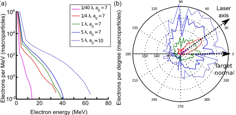
Figure 6.(a) Electron spectra for different front scale lengths, and for increased intensity for a long scale length integrated over the entire simulation box during the LPI, and (b) the angular profile of all electrons above 2.5 MeV, all ford=6µm.
in a regime relevant to this experiment, 2D PIC simulations were performed using the OSIRIS 2D3V PIC code [29]. The plasma was initialized in the simulation as fully ionized Al with a reduced density for numerical reasons (ne,max =70nc wherenc = 1.7×10²¹particles cm−3, the critical density), with different target thicknesses (0.3–6µm) and scale lengths on the front surface, with the maximum ofl =5λbeing that measured from the HELIOS simulations for the low contrast case for a nanosecond pre-pulse. A thin proton layer was initialized on the rear surface to model the impurity layer that ionizes and forms the proton beams measured in the experiment (thickness d = 50 nm, n = 40nc). A linearly polarized laser pulse (normalized vector potentiala0 =7 and 10, focal spot w0 = 3µm, pulse length τ = 35 fs) was incident at 35◦and focused on the front of the target before the addition of a front scale length, which most accurately represents the focusing geometry in the experiment. The simulation box was 60×128µm with cell size 6×8 nm, 25 macro-particles per cell for the electron species and 9 for the ion species. Convergence checks were performed at higher resolution and
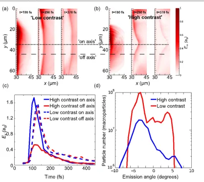
[image:5.595.103.500.286.480.2]Figure 7.(a) and (b) Magnitude of the electric fieldEmspatial profiles along the rear surface from a cropped region of the simulation box at different times in the simulation showing the difference in sheath evolution between high and low contrast cases ford=6µm, (c) time history of the maximum electric field at the proton front along axis (centre of rear surface expansion) and at +3w0(≈10µm) from the centre of expansion (as shown in (a) and (b) by a dashed line), and (d) divergence of the protons above 5 MeV, calculated from an angular histogram of the macro-particles from the px–py phase space, at the end of the simulation (tsim=450 fs), with 0◦being target normal.
laser–electron energy conversion efficiency (figure6(a)), but with a significantly higher beam divergence (figure 6(b)). The effect of changing the intensity with a fixed l = 5λ shows a similar angular distribution shifted to higher electron temperature and number related to the higher intensity and energy in the pulse. Although divergence angle of the final proton number depends on laser intensity for fixed conditions [16], the strong variation in electron angular distribution arising from plasma scale lengths is a key factor in determining the final angular divergence of the accelerated proton beam.
Two key parameters in determining the properties of the accelerated proton beam are the hot electron temperature, Thot, and number density, nhot, at the rear surface of the target. Although bothnhot andThot increase for higher laser intensity and increasing scale length,nhot at the rear surface depends also on the electron beam divergence angle and the longitudinal distance between the LPI and the rear surface. Indeed, considering the beam properties from figure7, the hot electron density, and therefore peak electric field, at the rear surface can be largerfor a lower intensity but with a short scale length, despite the decrease in both coupling efficiency and electron temperature.
To proceed with a comparison to the experimental data, we consider an example ‘high contrast’ case (i.e. short scale length) (a0 = 7, l = 1/4λ) and ‘low contrast’ (a0 = 10, l = 5λ) case. Figures7(a) and (b) shows the spatial profile of the magnitude of the accelerating sheath field,Em, along the rear surface after the peak of the acceleration for each case at three different times in the simulation. The sheath field typically points normal to the curvature of the electric field, which is tied to the position of the proton front. The final spatial profile of the field (and also the expanding proton species, whose front mirrors that of the field) is markedly different in the two cases. For the low contrast case the curvature, is significantly lower, and protons from a significantly larger transverse region on the rear surface are accelerated by the sheath, whereas for the high contrast case, the initial high electron density in a localized region results in a field that is strongly peaked on axis with only the protons within a few focal spots accelerated to the highest energies.
Figure 8.(a) Integrated proton energy spectra over all the particles in the simulation box at the end of the simulation for different target thicknesses for the ‘high contrast’ case, and (b) the angular divergence distribution of all protons>5 MeV.
centre, as shown in figures7(a) and (b). Despite the increased coupling to the electron species for the longer scale length and higher intensity, the peak electric field along the centre of expansion issmallerfor the higher intensity, long scale length interaction. However, due to the increased beam divergence and energy coupling to the electrons, the off-axis electric fields are significantly higher, resulting in a larger acceleration region on the rear surface. Furthermore, the field at tsim > 300 fs is significantly lower for the high contrast case, reflecting a shorter acceleration time due to the initial smaller coupling, as the hot electrons quickly spread out over the rear surface. This short acceleration time imprints itself on the final divergence of the proton beam at the end of the simulation (tsim=450 fs), shown in figure 7(d). The high contrast case shows a more collimated beam, albeit with longer wings. In addition, the beam is consistently bent slightly away from target normal towards laser axis [12] by around≈3◦due to sheath asymmetry related to the laser-axis direction acceleration byj×Bheating. This pointing was not clearly reproduced via the experiment, likely due to the predicted deviations being on the order of the angular uncertainty in the positioning of the target angle. In comparison, the longer scale length target shows a less collimated beam more evenly distributed around target normal. The divergence of the proton beam arises from the curvature of the sheath profile during the acceleration, resulting in the accelerating field pointing away from the original target normal direction [30]. However, crucially for the short scale length case, the initial rapid acceleration phase followed by the rapid reduction in accelerating field means that energy gain mostly occurs before the target significantly deforms. In comparison, for the low contrast case the higher field at late time, when the sheath field exhibits an increasingly curved spatial profile, imprints itself via an increased proton divergence. Note that the 2D simulations here will underestimate the diffusion of the hot electron population across the rear surface, which will further enhance the variation
innhot at the rear surface, and should therefore both enhance the difference between low and high contrast, and also result in larger divergences for both cases more comparable to those seen in the experiment.
Another feature of the experiment was a significant increase in flux for decreasing target thickness when using the plasma mirrors, whilst maintaining the same amount of collimation (see figures 3 and4). For a fixed fast electron injection angle, the resulting electron density at the rear surface would scale inversely with target thickness. It follows that a higher electron density would drive a stronger sheath field and hence result in a higher peak proton energy and total proton flux. To investigate the effect of a decreasing target thickness and its impact on the flux and the divergence of the accelerated proton beam, we performed a further series of PIC simulations in which the target thickness was varied between 0.3 and 6µm while keeping the front density scale length constant, with laser and scale length conditions otherwise matching the short scale length high contrast case above.
The resultant proton beam energies are shown in figure 8(a), demonstrating an increase in maximum energy and accelerated proton number towards the thinnest targets. Experimental data for the maximum proton energies observed for the high contrast data set have been published by Prasad et al[31]. While the maximum energies seen in these latest simulations are higher than that seen experimentally, the trend of decreasing energy with increasing target thickness is consistent. The lower energies seen experimentally could be accounted for by the limited sensitivity of the diagnostic to the relatively low flux at higher energies.
contrast was increased through the use of double plasma mirrors. Measurements of the laser ASE together with hydrodynamic simulations indicate that this increase cannot be attributed to ASE-driven low temperature shock-induced deformation of the accelerating surface at the rear of the target. 2D PIC simulations show that the observed results are instead attributed to the presence of a significant plasma scale length, on the order of 5λ, on the target front surface. This additional plasma significantly alters the absorption of the laser at the critical surface and enables additional electron acceleration mechanisms not present under high contrast conditions.
Simulations demonstrate that without the use of plasma mirrors, a long scale length plasma on the target front surface leads to a higher energy electron beam being injected into the target with a larger characteristic injection angle. This subsequently leads to higher electric fields over a larger area of the target rear surface that are sustained for a longer period. As a result a larger fraction of proton acceleration occurs at later times when curvature of sheath front is significant, hence the observed proton beam divergence would be larger. With plasma mirrors in place,j×Bdominated electron acceleration leads to a higher but more localized electron density at the rear surface, driving a rapid phase of proton acceleration that occurs before the target has time to deform significantly, resulting in a noticeably more collimated proton beam.
The experiment and simulation results also show that as the target thickness drops below 6µm the increase in fast electron density has a significant effect on the resulting proton beam, increasing both the maximum energy and total beam flux without adversely affecting the degree of beam collimation. It is clear that careful control of the laser contrast not only permits the use of ultra-thin targets for ion acceleration, but can noticeably reduce the observed proton
References
[1] Bulanov S Vet al2002Phys. Lett.A299240 [2] Malka Vet al2004Med. Phys.311587
[3] Ledingham K W Det al2004J. Phys. D: Appl. Phys.372341 [4] Krushelnick Ket al2000IEEE Trans. Plasma Sci.281184 [5] Roth Met al2001Phys. Rev. Lett.86436
[6] Wilks S Cet al2000Phys. Plasmas8542 [7] Macchi Aet al2013Rev. Mod. Phys.85751 [8] Daido Het al2012Rep. Prog. Phys.75056401 [9] Kaluza Met al2004Phys. Rev. Lett.93045003 [10] Mackinnon A Jet al2001Phys. Rev. Lett.861769 [11] Lindau Fet al2005Phys. Rev. Lett.95175002 [12] Zeil Ket al2010New J. Phys.12045015 [13] Dromey Bet al2004Rev. Sci. Instrum.75645 [14] Green J Set al2011Proc. SPIE8079807919
[15] Ziegler J Fet al2004Nucl. Instrum. Methods Phys. Res.B 2191026–36
[16] Bin J Het al2013Phys. Plasmas20073113 [17] Neely Det al2006Appl. Phys. Lett.89021502
[18] McKenna Pet al2007Plasma Phys. Control. Fusion49B223 [19] MacFarlane J Jet al2006J. Quant. Spectrosc. Radiat.
Transfer99381
[20] McKenna Pet al2008Laser Part. Beams26591 [21] Seo J Tet al2007J. Phys. Soc. Japan76114501 [22] Nuter Jet al2008Appl. Phys.104103307 [23] Santala M I Ket al2000Phys. Rev. Lett.841459 [24] Cheng Z Met al2002Phys. Plasmas93147 [25] Sentoku Yet al2002Appl. Phys.B74207 [26] Kemp Aet al2009Phys. Rev.E79066406 [27] Cai Het al2010Phys. Plasmas17023106 [28] Paradkar B Set al2011Phys. Rev.E83046401
[29] Fonseca R Aet al2002Lecture Notes in Computer Science
(Heidelberg: Springer) vol III-342 p 2329 [30] Carroll D Cet al2007Phys. Rev.E76065401(R) [31] Prasad Ret al2010Nucl. Instrum. Methods Phys. Res.A