City, University of London Institutional Repository
Citation
: Yeo, T. L., Sun, T. and Grattan, K. T. V. (2008). Fibre-optic sensor technologies
for humidity and moisture measurement. Sensors and Actuators A: Physical, 144(2), pp.
280-295. doi: 10.1016/j.sna.2008.01.017
This is the accepted version of the paper.
This version of the publication may differ from the final published
version.
Permanent repository link:
http://openaccess.city.ac.uk/14967/
Link to published version
: http://dx.doi.org/10.1016/j.sna.2008.01.017
Copyright and reuse:
City Research Online aims to make research
outputs of City, University of London available to a wider audience.
Copyright and Moral Rights remain with the author(s) and/or copyright
holders. URLs from City Research Online may be freely distributed and
linked to.
City Research Online:
http://openaccess.city.ac.uk/
publications@city.ac.uk
Fibre-optic sensor technologies for humidity and moisture measurement
T.L. Yeo
∗, T. Sun, K.T.V. Grattan
SchoolofEngineeringandMathematicalSciences,CityUniversity,NorthamptonSquare,LondonEC1V0HB,UK
Abstract
Areviewoftheuseoffibre-opticsensortechnologiesforhumiditysensingispresented.Thepaperfirstprovidesabriefoverviewonthebasic conceptofwhatismeantbyhumidityandonconventionaldetectionmethods.Thisisfollowedbyanextensivereviewonthevariousfibre-optic techniquesreportedforhumiditysensing,coveringbothintrinsicandextrinsicsensorconfigurations.
Keywords: Fibre optic; Sensors; Humidity; Moisture
Contents
1. Introduction . . . 281
1.1. Humidity sensing . . . 281
1.2. Humidity and relative humidity . . . 281
2. Conventional techniques for humidity detection . . . 281
2.1. Mechanical hygrometer . . . 281
2.2. Chilled mirror hygrometer . . . 282
2.3. Wet and dry bulb psychrometer . . . 282
2.4. Infrared (IR) optical absorption hygrometer . . . 282
2.5. Miniaturised humidity sensors . . . 282
2.5.1. Electronic sensors . . . 282
2.5.2. Optical waveguide sensors . . . 282
3. Fibre-optic techniques for humidity detection . . . 282
3.1. Direct spectroscopic-based sensors . . . 283
3.1.1. Absorption-based sensors . . . 284
3.1.2. Fluorescence-based sensors . . . 286
3.2. Evanescent wave sensors . . . 286
3.2.1. Optical absorption . . . 287
3.2.2. Refractive index change . . . 288
3.2.3. Light scattering . . . 289
3.3. In-fibre grating sensors . . . 290
3.4. Interferometric sensors . . . 292
4. Summary . . . 293
Acknowledgement . . . 293
References . . . 293
∗Corresponding author. Tel.: +44 20 7040 3641.
1. Introduction
1.1. Humidity sensing
In a similar way to temperature, strain or pressure for exam-ple, humidity (or moisture content) constitutes one of the most commonly required physical quantities. It has shown significant importance in a diverse range of applications, as illustrated in
Fig. 1, from air conditioning for human comfort and combat-ing bacterial growth to process control and maintaincombat-ing product
quality [1]. The requirements for humidity monitoring may
vary according to the application and hence various techniques have been employed to perform humidity measurements. In this paper, a brief overview on the basic concepts and definitions associated with humidity measurements is given but the focus is on the design and use of novel fibre-optic-based methods for humidity sensing, which are discussed and reviewed in this paper.
1.2. Humidity and relative humidity
The termhumidityrefers to the presence of water in gaseous
form but it is often used to refer to expressions which are related to water vapour characteristics and in the field of measure-ment, there are various terms associated with such water vapour
measurements. In addition, the termmoistureis frequently
inter-changed with humidity even though the actual definition of
moisturerefers to the water in liquid form that may be present
in solid materials[2]. Since humidity is a measure of water in
gaseous state present in the environment, water vapour found in a gas mixture behaves in accordance with the gas laws and the amount of pressure it exerts equates to the partial pressure of the water vapour components in the gas mixture, as defined by
Dalton’s law[2].
When air is fully saturated with water, the pressure exerted by the water vapour present is defined as the saturation water
vapour pressure (Pws) which is a function of temperature. A
common way to relate the amount of water vapour present in the environment is to take the ratio of the actual water vapour pressure and the saturation water vapour pressure at a specific
temperature. The resultant term, known as therelative humidity
[image:3.637.48.287.584.727.2](RH), simply represents the ratio of the amount of water vapour
Fig. 1. An example of applications of humidity sensors in various industries.
present in the atmosphere to the maximum amount the atmo-sphere can hold and is often expressed as a percentage using the following equation,
Relative Humidity (RH)= Pw
Pws×
100% (1)
wherePwis the partial pressure of the water vapour andPwsis
the saturation water vapour pressure.
If air is cooled down sufficiently, to a point where it becomes saturated with water molecules (RH = 100%) and condensation occurs as a result, the temperature at which this occurs is known
as thedew point. In a similar way to relative humidity, the dew
point temperature is another term frequently used to express the amount of water vapour present in the atmosphere. It is much preferred in some applications, for example, in meteo-rology, as it provides a better “absolute” measurement of water vapour content than RH measurements, which may fluctuate with temperature.
The dew point temperature or RH can be calculated by using
the familiar dry and wet bulb temperature method[2], where the
name was derived from the technique employed which involves using regular bulb thermometers to perform temperature mea-surements. Other parameters which include humidity ratio or moisture content expressed as a dimensionless quantity and
absolute humidity, expressed in g/m3, are also used in humidity
measurements.
2. Conventional techniques for humidity detection
In order to cross-compare the approaches to measurement using fibre-optic technologies, a brief overview of conventional
techniques[2]for humidity sensing follows. From the simplest
way of exploiting the expansion and contraction of materials such as human hair to the most sophisticated techniques, such as using a miniaturised electronic chip, a variety of methods have been explored over many years to obtain meaningful humidity measurements. These methods are employed either by probing the fundamental properties of water vapour or using various transduction methods which are capable of giving humidity-related measurements.
2.1. Mechanical hygrometer
2.2. Chilled mirror hygrometer
The chilled mirror hygrometer, also known as the optical condensation hygrometer, is a device based on an optical tech-nique for the determination of the dew point temperature. It is known to be the technique which provides the most accurate and reliable measurements, and is often used for measurements set-ting a calibration standard. In operation, a conventional chilled mirror hygrometer contains a temperature-controlled reflective condensation mirror and an optoelectronic module which mon-itors the optical signal reflected from the surface of the mirror. In the ‘dry’ condition, where the mirror temperature is higher than the dew point, the maximum signal is reflected into the detector of the optoelectronic module. When the temperature drops below the dew point, the signal intensity is reduced due to the scattering of light as a result of water droplets forming on the mirror surface. The chilled mirror hygrometer can be used to provide measurements with accuracy quoted to be as
high as ±0.1◦C [2]. However, this method is expensive and
requires regular maintenance due to its susceptibility to surface contamination.
2.3. Wet and dry bulb psychrometer
A simple and relativity low cost method which has been popular for humidity measurements is the wet and dry bulb psychrometer. It consists of two thermometers (e.g., electric or glass), one of which is covered with a damp wick to determine the wet bulb temperature and the other to measure the temper-ature of the sampled gas (dry bulb tempertemper-ature). The dry bulb temperature is simply the temperature of the air, whereas the wet bulb temperature is the temperature achieved as a result of water evaporation and latent heat transfer. Examples of such measuring device are the sling psychrometer which operates by whirling the device through the air to obtain the temperature readings and the Assman psychrometer, a similar device with a fan attached to the unit to provide air flow.
This measurement device is relatively inexpensive, yet can also be used to provide a calibration standard. However, it is not suitable for operation in small enclosed areas (where the mois-ture from the wet bulb significantly changes the water vapour content in the environment) and precautions are necessary to minimise measurement errors caused by contamination on the wick covering the thermometer, inconsistency in the wetting of the wick and the inaccuracy of the thermometers used. Generally, such a measuring device using thermometers with a temperature
accuracy of±0.2◦C offers humidity accuracy of±3%RH when
operating over a temperature range of 5–80◦C[2].
2.4. Infrared (IR) optical absorption hygrometer
The general operation principle of the IR hygrometer is based on a dual-wavelength absorption technique that uses a primary wavelength at which strong optical radiation absorp-tion is observed and a secondary/reference wavelength where the absorption is negligible. Humidity measurements are then taken in the form of transmission ratios at these two chosen
wavelengths. This technique allows the direct measurement of water absorption which minimises drift in the readings and also interference caused by contaminants such as particles and other gaseous species in the test environment. The sensitivity of the instrument is dependent on the absorption path length and is
thus governed by the Beer–Lambert law[3]where the
transmis-sion of the IR radiation through the absorbing gas is inversely proportional to the exponential function of gas concentration and the path length. This instrument has negligible drift and can generally operate over a wide humidity range.
2.5. Miniaturised humidity sensors
2.5.1. Electronic sensors
The development of these miniaturised electronic humidity sensors have been driven by the demand for low cost, reli-able and compact sensors and transduction methods reported include capacitive, resistive and gravimetric methods. An exten-sive review on these sensors and their performance has been
conducted recently by Lee and Lee[4]. A similar review has been
carried out by Chen and Lu[5]with an emphasis on the wide
range of sensing materials employed by the different humidity sensor types.
Amongst the various humidity sensors discussed, the capacitive- and resistive-based humidity sensors are the most commonly used, with capacitive-based sensors dominating and making up nearly 75% of the commercial humidity sensor
mar-ket[6]. Capacitive-based humidity sensors operate on the basis
of dielectric changes of a thin hygroscopic film upon exposure to moisture. Resistive-based sensors rely on the transduction mechanism involving the change in conductivity caused by the absorption of moisture in a hygroscopic material such as conduc-tive polymers. Generally, both sensor types, which are classified as secondary measurement devices, are inexpensive and have low power consumption, covering a wide humidity range with good repeatability but suffer from temperature dependency and cross-sensitivities to some chemical species.
2.5.2. Optical waveguide sensors
Optical waveguide sensor is a class of optical-based device that falls under the category of miniaturised humidity sensors.
An example is the surface relief gratings on SiO2/TiO2
waveg-uides reported by Tiefenthaler and Lukosz[7]. The roles played
by surface and volume adsorption of water molecules were deter-mined quantitatively from the measurements of the effective refractive index changes of certain modes in the waveguide. The observed changes in the refractive index as a result of water adsorption were 0.037 at a wavelength of 514.5 nm and thus the number of monolayers of water adsorbed can be determined under different conditions.
3. Fibre-optic techniques for humidity detection
measurements, have their own particular advantages and dis-advantages yet none of them can fulfil majority of the requirements of precision, cost, ease of operation and main-tenance, background interference, operation environment and remote operation. These sensors however, are generally not suit-able to be employed in an environment of a potentially hazardous or explosive nature and also in situations where requirements such as immunity to electromagnetic interference, multi
sen-sor operation,in situand remote monitoring are, for example,
required. Fibre optics offers a new approach to this new mea-surement problem.
With the advent of optical fibre technology, a considerable level of research has been focused on fibre-optic (FO)-based techniques for humidity sensing. In a similar way to their electronic or mechanical counterparts, FO humidity sensors are secondary devices but show additional features like small size, immunity to electromagnetic interference, multiplexing and remote sensing capabilities, of which the counterpart elec-tronic sensors lack. However, the limitations of the operating range and accuracy of the FO-based humidity sensors are some of the drawbacks which researchers are striving to continue to address. Nevertheless, these sensors have found useful appli-cations in various areas where electronic sensors were found to be inappropriate, thereby showing the real potential of FO-based sensors. Thus, this forms the main motivation that has driven the
research activities on the development of a range of FO humidity sensors over the last 20 years.
The various FO-based humidity sensing techniques reported so far, with designs covering both extrinsic and intrinsic sen-sor types, can be further classified according to the techniques
commonly employed in optical fibre sensing [8,9]. Generally,
these techniques include direct spectroscopic, evanescent wave, in-fibre grating and interferometric methods, as discussed in detail below. Techniques employed vary from those which use an optical property of a material in response to humid-ity change to optical or fibre optic analogues of the different
non-optical sensors described in the previous section. Table 1
has been designed to provide an overview and summary of the results reported by a number of the authors cited in this paper, bringing together the results of published work reported by their authors in a way that enables a degree of cross-comparison on a quantitative basis. In some cases data are not available (and therefore there are blanks in the table), but as such it enables a high degree of evaluation of different systems.
3.1. Direct spectroscopic-based sensors
[image:5.637.49.559.414.740.2]The spectroscopic method has been a ‘workhorse’ technique widely used in chemical analysis. This method examines the
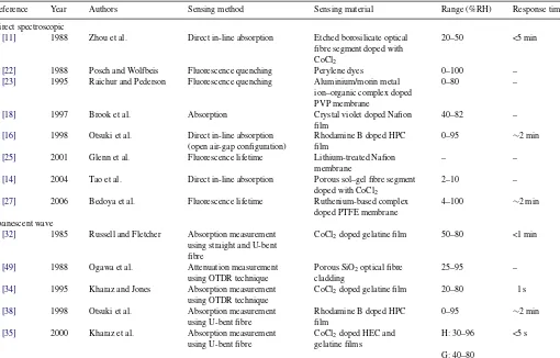
Table 1
Overview of the various fibre-optic sensing techniques for humidity detection
Reference Year Authors Sensing method Sensing material Range (%RH) Response time
Direct spectroscopic
[11] 1988 Zhou et al. Direct in-line absorption Etched borosilicate optical fibre segment doped with CoCl2
20–50 <5 min
[22] 1988 Posch and Wolfbeis Fluorescence quenching Perylene dyes 0–100 –
[23] 1995 Raichur and Pederson Fluorescence quenching Aluminium/morin metal ion–organic complex doped PVP membrane
0–80 –
[18] 1997 Brook et al. Absorption Crystal violet doped Nafion film
40–82 –
[16] 1998 Otsuki et al. Direct in-line absorption (open air-gap configuration)
Rhodamine B doped HPC film
0–95 ∼2 min
[25] 2001 Glenn et al. Fluorescence lifetime Lithium-treated Nafion membrane
– –
[14] 2004 Tao et al. Direct in-line absorption Porous sol–gel fibre segment doped with CoCl2
2–10 –
[27] 2006 Bedoya et al. Fluorescence lifetime Ruthenium-based complex doped PTFE membrane
4–100 ∼2 min
Evanescent wave
[32] 1985 Russell and Fletcher Absorption measurement using straight and U-bent fibre
CoCl2doped gelatine film 50–80 <1 min
[49] 1988 Ogawa et al. Attenuation measurement using OTDR technique
Porous SiO2optical fibre
cladding
25–95 –
[34] 1995 Kharaz and Jones Absorption measurement using OTDR technique
CoCl2doped gelatine film 20–80 1 s
[38] 1998 Otsuki et al. Absorption measurement using U-bent fibre
Rhodamine B doped HPC film
0–95 ∼2 min
[35] 2000 Kharaz et al. Absorption measurement using U-bent fibre
CoCl2doped HEC and
gelatine films
H: 30–96 <5 s
Table1(Continued)
Reference Year Authors Sensing method Sensing material Range (%RH) Response time
[43] 2000 Bariain et al. Attenuation measurement using tapered fibre
Agarose gel 30–80 <1 min
[39] 2001 Gupta and Ratnanjali Absorption measurement using U-bent fibre
Phenol red doped PMMA film
20–80 –
[36] 2002 Jindal et al. Absorption measurement using straight and U-bent fibre
CoCl2doped PVA film S: >78
U: 3–90
[41] 2003 Muto et al. Attenuation measurement using PMMA plastic optical fibre
HEC/PVDF film 20–80 <5 s
[42] 2003 Arregui et al. Attenuation measurement Hydrogels-Agarose gel, poly-HEMA, poly-N-VP, poly-acryamide
Agarose: 10–100 ∼90 s
[47] 2004 Gaston et al. Attenuation measurement using side-polished fibre
PVA film 50–90 1 min
[48] 2004 Alvarez-Herrero et al. Wavelength resonance shift using side-polished fibre
TiO2overlay 0–80 –
[50] 2004 Xu et al. Attenuation measurement Porous sol–gel cladding 3–90 <1 min
[44] 2006 Corres et al. Attenuation measurement using tapered fibre
PDDA/Poly R-478 nanostructured sensing overlay using ISAM technique
75–100 –
In-fibre grating
[57] 2002 Kronenberg et al. Strain-induced Bragg wavelength measurement
Polyimide 10–90 –
[63] 2002 Luo et al. LPG resonant band wavelength measurement
CMC 0–95
[66] 2005 Tan et al. LPG resonant band intensity measurement
Gelatine 90–99
[67] 2005 Konstantaki et al. LPG resonant band intensity and wavelength measurement
CoCl2doped PEO film I: 70–80 <1 s
W: 40–80 Interferometric
[68] 2007 Venugopalan et al. LPG resonant band intensity measurement
PVA 33–97 –
[73] 1989 Mitschke Intensity measurement using Fabry–Perot configuration
SiO2–TiO2–SiO2cavity 0–80 1 min
[74] 1999 Arregui et al. Intensity measurement using Fabry–Perot configuration
SiO2–[Au:PDDA + /PSS-]-air
cavity using ISAM technique
11–100 1.5 s
[78] 1999 Kronenberg et al. Tandem Michelson interferometer configuration
PUU-PEO/PPO Hydrogel – –
[76] 2001 Yu et al. Intensity measurement using Fabry–Perot configuration
SiO2–[PDDA + /PS-119]-air
cavity using ISAM technique
0–97 3 s
optical signal obtained and relates absorption or fluorescence-based measurements to the concentration of the target analyte. Hence it is not surprising that it is a popular choice of method for many FO-based chemical sensors. Generally, as shown in
Fig. 2, the design of the sensors can simply comprise optical fibres with a sample cell for direct spectroscopic measure-ments or be configured as fibre optrodes where a chemical selective layer, comprising chemical reagents in suitable
immo-bilising matrices, is deposited onto the optical fibre [9,10].
Most spectroscopic-based configurations for humidity sens-ing are based on the optrode design where moisture sensitive reagents are attached to the tip of the sensing fibre, usually with the aid of a polymeric material to form the supporting matrix.
3.1.1. Absorption-based sensors
A variety of potential materials and chemical reagents have been reported in light of their humidity-dependent opti-cal absorption properties. Examples include reagents such
as cobalt chloride (CoCl2) [11–14], cobalt oxide (Co3O4)
[15], Rhodamine B [16] crystal violet [17,18], and more
recently, materials such as eletrochromic polymers [19] and
bacteriorhodopsin (BR) doped biochromic film[20], where
mea-surements are made by monitoring the intensity variation as a result of absorption due to the interaction between the chemical reagents involved and moisture.
Examples of such sensors include those from Zhou et al.[11]
who have demonstrated an in-line absorption-based humidity
[image:6.637.38.555.77.552.2]Fig. 2. Various configurations for spectroscopic fibre-optic sensors[16].
an inorganic salt compound which exhibits strong absorption on the wavelength band between 550 and 750 nm. As it hydrates, the colour of the salt compound changes from blue to pink and the absorption peak undergoes a hypsochromic shift. The use of the absorption characteristics of the compound contained in a variety of materials such as gelatine and cellulose has
also been discussed by various authors [12,13]. To create a
sensing element from these materials, a 0.5 cm long borosili-cate glass fibre, with a typical diameter ranging from 150 to
300m was pre-treated to create a porous structure before being
immersed into a aqueous CoCl2 solution, followed by being
dried at room temperature. As the sensing element is porous, some of the light launched into the fibre will be absorbed by the reagent and some will be scattered out of the structure. Hence the scattering loss was taken into consideration when
Fig. 3. SEM picture of the porous sol–gel silica fibre, showing the interconnected porous structure on the surface of the fibre[14].
the humidity-dependent absorption measurements were made. Sensor operation up to a limit of 50%RH was observed and the operating range was found to be dependent on the
concen-tration of the CoCl2solution used for the fibre treatment. The
sensor configuration discussed shows good reversibility and has a response time of 2–3 min.
Tao et al.[14]have recently demonstrated an active fibre core
optical sensor (AFCOS) for humidity detection using a similar in-line absorption sensing concept. The porous sensing element was created using the sol–gel technique. Instead of pre-treating a segment of porous silica fibre with chemical reagent, the sens-ing element was mould-cast ussens-ing a sol solution premixed with
CoCl2, shown inFig. 3. This method offers more flexibility and
it can be easily tailored to meet specific sensor requirement by controlling the dimension, composition and porosity of the sol gel silica structure. The demonstrated sensor consists of a 0.2 cm
long CoCl2doped sol–gel silica fibre (diameter: 390m) with
both ends attached to optical fibres of similar diameter. The opti-cal signal at 632 nm, propagating through the active fibre core, was monitored to obtain information on the humidity level. The sensor described was reported to exhibit good response and is able to detect humidity level down to 2%RH. However, the upper operating limit for the current sensor design is <10%RH, which can be tailored by adjusting the dopant concentration.
[image:7.637.323.553.65.203.2] [image:7.637.153.457.553.728.2]Otsuki et al.[16]have discussed an air-gap design, shown in
Fig. 4, utilising the in-line absorption configuration. The sensor demonstrated was formed with an air-gap between two sections of a large core fibre positioned on the same axis. One end of the fibre was dip-coated with a dye solution containing Rhodamine B (RB) and hydroxypropyl cellulose (HPC). To measure the optical signal as a function of humidity, light was coupled into the sensor from one end of the fibre, passing through the dye-doped film and collected by the other fibre. The sensor discussed is able to operate between 0 and 95%RH and has a response time of approximately 2 min.
3.1.2. Fluorescence-based sensors
A humidity-sensitive optrode membrane fabricated using a dye-doped (Rhodamine 6G) gelatine film has been discussed by
Choi and Tse[21]. The sensing membrane, which can be readily
adapted for FO sensing, exhibits strong fluorescence at 568 nm when excited at 536 nm. A hypsochromic shift was observed with a resultant decrease in the emission intensity at 568 nm when the humidity level was increased from 0 to 100%RH.
The use of the fluorescence quenching mechanism for
humid-ity detection has been explored by Posch and Wolfbeis [22].
The perylene-based sensor, implemented by attaching the sens-ing film at the end of a fibre bundle which forms the common arm of a bifurcated FO light guide, was evaluated over the range from 0 to 100%RH and the sensor response was found to be both non-linear and unfortunately exhibited cross-sensitivity to oxygen.
A similar approach using a quenching mechanism was
demonstrated by Raichur and Pedersen [23]. The sensor,
designed for applications in drying and baking processes, employs a highly fluorescent film based on aluminium/morin complex immobilised in polyvinyl pyrrolidone (PVP). The quenching of the fluorescence emission from the metal ion–organic complex, which arises due to the interaction between the aluminium ions and moisture, exhibits a linear response that follows the Stern–Volmer equation. The sensor showed good humidity response when assessed at elevated
tem-peratures, up to 90◦C. However, prolonged testing showed a
20% decrease in output signal which could be attributed to the choice of polymer matrix used.
Luminescence lifetime-based methods [24–27]can also be
considered to overcome some of the issues encountered by the intensity-based method such as the re-absorption of the fluo-rescence signal, scattering, light intensity variations and the concentration of the luminescence compounds used. The use of luminescence lifetime-based system using ruthenium-based
complex immobilised in Nafion©membrane for the
measure-ment of water content in organic solutions and humidity in the
air has been discussed by Glenn et al.[25]. This sensor was able
to respond to the change of water in both the liquid and gaseous phases but the operational lifetime of the sensing component is only about 4 days and it requires a regeneration procedure to restore its functionality. A more robust and stable sensing sys-tem, using the same ruthenium complex immobilised in a PTFE
disk, was recently demonstrated by Bedoya et al.[27].
Phase-sensitive detection for humidity measurements was employed
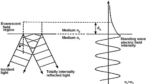
Fig. 5. Evanescent field generated at the interface of two optically transparent media[29].
using a modified commercial lifetime-based instrument. The optrode fabricated has an operational range of 4–100%RH and displays good performance in terms of response time, repeata-bility and starepeata-bility.
3.2. Evanescent wave sensors
Light travelling through a step index optical fibre is guided within the medium as a result of total internal reflection (TIR)
if the critical angle criterion is fulfilled[28]. At each point of
TIR, the interference between the incident and reflected signals,
shown inFig. 5, at the core/cladding interface generates a
stand-ing wave which extends beyond the core of the optical fibre and penetrates into the cladding region.
This creates an evanescent field with an amplitude that decays exponentially with distance away from the core/cladding inter-face and follows the form,
E(z) = E0exp
z dp
(2)
where the penetration depth (dp) is defined as the depth at which
the amplitude of the evanescent field,E, has decayed to 1/e of the
initial valueE0at the core/cladding interface and this is given
by
dp= λ
2πncore[sin2θ−(nclad/ncore)2]
1/2 (3)
whereλis the wavelength of the propagating signal in the optical
fibre,θis the angle of incidence normal at the interface,ncore
andncladare the refractive indices of the fibre core and cladding,
respectively.
The evanescent wave (EW) sensing method allows the optical fibre to be used as an intrinsic sensor where the field generated at the interface interacts with the target analyte surrounding the fibre, thus giving information as a result of optical absorption,
refractive index change or scattering[30].
[image:8.637.305.549.65.206.2]Fig. 6. Optical responses of distributed fibre-optic sensing system using optical time domain reflectometer (OTDR)[34].
form a U-bent fibre, causing the evanescent field to extend fur-ther away from the interface, hence enhancing the interaction between light and the target analyte. Other methods to gain access to the evanescent field include side polishing of optical fibres cast in a polymer block to expose the fibre core or heating and stretching the optical fibre to form a fibre taper.
Chemical reagents or selected matrices can be coated onto a de-clad optical fibre, forming a common design configuration for EW absorption- or fluorescence-based sensors. Comparing these to the sensors discussed in the previous section, the use of such a configuration gives flexibility in terms of the interaction
length, time response and distributed sensing capability [31].
However, the required optical path length to achieve a similar sensitivity as is achieved for example in the direct absorption method either by using a direct sample cell or configuration
based on active fibre core[11,14], is much longer due to the
small path length interaction at every reflection point along the
fibre[14,30].
3.2.1. Optical absorption
The majority of the EW methods reported are based on the absorption principle, which involves the use of chemical reagents immobilised in suitable organic or inorganic matri-ces. One of the earliest EW absorption-based humidity sensor
was demonstrated by Russell and Fletcher[32]in 1985 using a
600m optical fibre with 12 cm of CoCl2/gelatine sensing film.
Ballantine and Wohltjen [33] then proposed a similar sensor
the following year, using a 9 cm long glass capillary waveguide
coated with CoCl2/poly(vinylpyrrolidone) (PVP) film. In both
the sensors discussed, the general operating range was limited and they could only respond to a humidity level higher than 50%RH.
Using the same chemical reagent and organic film
combina-tion (CoCl2/gelatine), Kharaz and Jones[34]later demonstrated
a quasi-distributed FO humidity sensing network consisting of 4
sensors using a 200m hard clad silica fibre with each sensing
point positioned about 20 m apart. Measurements were obtained
using an optical time domain reflectometry (OTDR) technique,
shown in Fig. 6, utilising dual pulsed laser diodes emitting at
670 nm and 850 nm. An operating range of 20–80%RH was demonstrated using the sensor network and the performance was
reported to be stable for a temperature range from 25 to 50◦C.
Kharaz et al. [35]extended their research work by
investi-gating the influence of the immobilising matrices on the sensors performance. This was carried out by comparing various immo-bilising materials, such as hydroxyethylcellulose (HEC) and
gelatine, together with CoCl2. A U-bent fibre configuration,
shown inFig. 7, was used during the evaluation to enhance the
interaction of the evanescent field with the sensing film. From the studies performed using films of a similar reagent/immobilising material ratio, gelatine film was found to be insensitive below 40%RH, whereas HEC was able to respond to the 30–96%RH range, hence clearly showing the influence of the film constituent on the operating range of the sensor. This observation was substantiated by the work discussed by Jindal
et al. [36]. In their research, a U-bent humidity sensor using
CoCl2/polyvinyl alcohol (PVA) film was reported to be
sensi-tive to a humidity range from 3 to 90%RH. Further detailed work
to optimise the performance of the CoCl2/PVA sensor was then
undertaken by Khijwania et al.[37], in which the effects of film
thickness, bend radius and fibre core diameter were investigated.
In addition to CoCl2, which from the literature seems to
be a common choice of reagent used in the EW absorption-based humidity sensors discussed so far, other reagent/
[image:9.637.315.562.644.719.2]Fig. 8. Evanescent wave POF humidity sensor using PMMA core and HEC/PVDF film. (a) Sensor configuration. (b) Refractive index change of HEC/PVDF film at various humidity conditions. (c) Sensor characteristics[41].
immobilising matrix combinations deposited on U-bent
sen-sors have also been reported by various authors [38–40].
These include Rhodamine B/hydroxypropyl (HPC) film, phe-nol red/polymethylmethacrylate (PMMA) film and magnesium oxide sol–gel film, with reported operating ranges of 0–95%RH, 20–80%RH and 5–85%RH, respectively.
3.2.2. Refractive index change
Refractive index (RI) change is another approach frequently used in the EW sensing method. An example of humidity sens-ing based on this method was demonstrated by Muto et al.
[41] using a plastic optical fibre (POF) as shown in Fig. 8.
The fibre core of the POF (diameter: 1 mm) was made from PMMA with a refractive index of 1.489 at 680 nm. Hence to render the fibre responsive to humidity, a polymer blend of HEC/polyvinylidenefluoride (PVDF) was deposited on the
fibre core, forming a cladding layer (thickness: 0.5–1m). The
humidity-sensitive cladding layer has a refractive index value of 1.492 when in dry state, creating a lossy waveguide which reduces the intensity of the light propagating through the fibre. As the cladding layer hydrates, the refractive index value falls below that of the core, reducing the intensity loss, thus forming the basis for humidity detection. The sensor responded well to a humidity range of 20–80%RH, with negligible temperature dependence. The time response to a step humidity change of 50%RH was reported to be less than 5 s.
Extensive studies were carried out by Arregui et al. [42]
using hydrogels, a class of polymeric material known for its excellent water absorption properties, as potential mate-rial for the sensing approach is discussed in this section. The evaluation was performed using de-clad optical fibres coated with poly-hydroxyethyl metharyclate (poly-HEMA),
poly-acrylamide, poly-N-vinyl pyrrolidinone (poly-N-VP) and
agarose gel, taking into account of the effect of pore size for the selected materials on the sensitivity and time response of the sensor. Among the materials tested, the sensor with agarose gel gives the best overall performance, achieving an operating range of 10–90%RH. It was also reported to exhibit a better response time and stability than rest of the materials evaluated.
The use of a tapered fibre with agarose gel for humidity sens-ing based on refractive index change has been demonstrated
by Bariain et al.[43]. The sensor consists of a tapered
single-mode telecommunication grade fibre with a waist size of 25m,
coated with agarose gel of a similar mix concentration to that
described by Arregui et al.[42]and a comparison was made
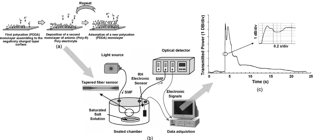
between the two different sensor types using the same mate-rial. The tapered sensor was reported to have a similar operating range and time response to the sensor using a de-clad fibre. How-ever, the dynamic range of the optical intensity measurements taken in a similar test was found to be much higher than that for the tapered fibre sensor. Using on the same approach, humidity sensors with nanostructured films deposited onto tapered fibres using the ionic self-assembled monolayer (ISAM) deposition
technique have been discussed recently[44,45]and are shown
inFig. 9. The ISAM deposition technique proposed allows the sensitivity of the sensor to be optimised by controlling the thick-ness of the coating film and a faster time response (than for the previous sensors discussed) was also possible due to the thin sensing film used.
Employing a side-polished optical fibre with a humidity-sensitive overlay represents another scheme for humidity sensing. To expose the evanescent field and create such a sen-sor, the flat surface parallel to the fibre axis was polished back to remove the cladding. Side polishing can be realised by first immobilising the optical fibre in a rigid material, forming a rect-angular block with fibre extending out from the two end faces of the block orthogonal to the fibre axis. The advantage of using this scheme is that the sensing element can be fabricated using inexpensive components and a variety of coating materials can be deposited onto the flat surface of the fibre block. However, the fabrication procedure is very time consuming and depending on the design of the fibre block and the exposed interaction length can be limited.
Gaston et al.[46,47]have proposed a humidity sensor based
on a single mode, side-polished fibre with a PVA overlay. The fibre block, with an exposed interaction length of about 2–3 mm, was covered by a PVA layer with thickness in the order of
differ-Fig. 9. Tapered optical fibre humidity sensor with ISAM overlay. (a) Schematic of ISAM deposition process. (b) Experimental set-up for sensor characterisation. (c) Sensor response to a short abrupt change of humidity simulated by human breath[45].
ent laser sources emitting at 1550 nm and 1310 nm, respectively. Both wavelengths showed a different sensing characteristic, with
1550 nm giving an operating range of∼50–90%RH (dynamic
range: 2.2 dB) and 1310 nm of∼70–85%RH (dynamic range:
8.2 dB).
A sensor designed for low humidity detection and based on
side-polished fibre, using a titanium oxide (TiO2) overlay was
[image:11.637.49.558.64.291.2]demonstrated by Alvarez-Herrero et al.[48] and is shown in
Fig. 10. The nanostructure overlay was deposited over the pol-ished fibre block by using the electron beam evaporation method. The humidity-induced optical response of the sensor was mon-itored in the form of a wideband optical spectrum consisting of resonance bands which satisfied the phase matching conditions. The resonances found at specific wavelengths occur when the refractive index of the fibre guided mode is equal to that of the highest order mode of the overlay, thus resulting in coupling of the optical signal from the fibre to the overlay. Depending on the refractive index value of the overlay, the wavelength of the
resonance shifts accordingly to fulfil the phase matching con-dition. This forms the basis of the sensing scheme, created by monitoring the wavelength shift of the resonance bands. The sensor demonstrated shows a linear wavelength shift from 0
to 15%RH, with a sensitivity of ∼0.5 nm/%RH. As the RH
level increases beyond 20%RH, the sensitivity of the sensor
decreases (∼0.03 nm/%RH for 30–80%RH), showing a smaller
wavelength change.
3.2.3. Light scattering
EW sensors based on a light scattering phenomenon can be realised by having a porous material acting as the cladding in the optical fibre structure. This porous cladding layer scatters the evanescent wave that extends from the fibre core, thereby caus-ing a reduction in the intensity of the optical signal propagatcaus-ing along the fibre. As the cladding layer absorbs water molecules, the scattering phenomenon is more evident, resulting in a further decrease in the transmitted optical power.
Fig. 10. (a) Experimental set-up for monitoring humidity-induced resonance band shift of a side-polished optical fibre with TiO2overlay. (b) Sensor response to
[image:11.637.105.504.569.720.2]The use of the EW light scattering technique for humidity
sensing was demonstrated by Ogawa et al.[49]using a silica
core fibre with a porous SiO2cladding. A sensor with an
inter-action length of 40 mm was evaluated using an LED emitting at 850 nm. The sensor was demonstrated both as a point sen-sor (optical transmission power measurements at 850 nm) and a distributed sensing system, formed by cascading three similar sensors along the same fibre and interrogated using the OTDR technique. The sensor evaluated was found to respond well to humidity change from 20 to 95%RH, with a small temperature variation dependence of 0.1 dB (the test temperature range used
was: 20–100◦C).
A similar scattering approach for humidity sensing was
dis-cussed by Xu et al. [50]. In their work, a U-bent configured
EW humidity sensor was implemented using sol–gel technol-ogy, thus providing a flexible means of synthesizing custom coating solution to create the porous sol–gel silica film. A light source of a similar emitting wavelength at NIR as employed by
Ogawa et al.[49], was used during the evaluation, in order to
minimise the influence of the Rayleigh scattering effect which dominates at the shorter wavelength range.
3.3. In-fibre grating sensors
The in-fibre grating sensor represents a class of intrinsic FO sensor that has gained widespread popularity in recent years. It has been used in numerous applications in various industries due to its inherent sensitivity to temperature, strain and
refrac-tive index change[51–53]. The grating structure within the fibre
sensor is created by UV-induced periodic refractive index mod-ulation of the fibre core and can be generally classified into two main categories depending on the grating period, namely the
fibre Bragg grating (FBG)[51]and long period grating (LPG)
[53].
The detailed description and operation of the FBG and LPG
has been discussed in the literature[51,53]. Grating-based
sen-sors are commonly used in chemical sensing. The LPG can be employed as a general refractive index sensor and used in conjunction with chemical selective materials to create a species-specific chemical sensor. This thus forms a very attrac-tive refracattrac-tive index based chemical sensing mechanism which has been employed in the detection of a variety of chemical
species [53]. The FBG-based sensors, on the other hand, are
on the whole used predominantly for the monitoring of physical parameters such a temperature, strain or pressure. To use an FBG as a chemical sensor, a common approach is to select a material selectively sensitive to the chemical measurand and capable of inducing mechanical deformation as it interacts. This is done to produce a secondary strain-induced measurement using the FBG sensor as a result of physical or chemical interactions. The selection of the sensing materials for a FBG chemical sensor is therefore more stringent than LPG as it should not only be responsive to the selected chemical species but also be able to expand in order to induce strain on the FBG. Applications of FBGs in chemical sensing reported so far are largely limited
to the important fields of hydrogen gas detection[54], salinity
measurement[55]and moisture sensing[56–58].
The concept of in-fibre grating devices for humidity sensing is still fairly new. To date, there have only been a few literature reports on the subject, the earliest of which dates back to the year 2001. Humidity sensing using a FBG was first reported
by researchers from EPFL, Switzerland [56,57] where
stud-ies were carried out to investigate the influence of humidity on commercial polyimide-recoated FBGs. The findings from the investigations concluded that an FBG with polyimide coat-ing was able to respond linearly over a wide humidity range. The sensor was reported to respond well to a humidity range of 10–90%RH and display good repeatability. Due to its inher-ent sensitivity to temperature, a compensation scheme was required to extract humidity measurements from the sensor read-ings. The same sensing scheme proposed for humidity sensing was further explored by various groups and has been demon-strated in several interesting applications which include soil
[image:12.637.78.504.596.718.2]moisture monitoring[59,60]and moisture detection in concrete
[61,62].
As an example of the use of this approach, work reported by
Kunzler et al.[60]demonstrates a polymer-coated FBG sensor in
soil moisture monitoring and was aimed at exploring the feasibil-ity of using such a sensor configuration in hazardous waste sites. The specific requirement defined for the application in question was to have a sensor capable of operating between 2 and 18% gravimetric soil moisture level. The measurements were taken by relating the soil moisture levels to the Bragg wavelength, which were calibrated against relative humidity. The method used however, only allows measurement of up to 4% gravimet-ric soil moisture level due to the saturation (100%RH) of the
Fig. 11. (a) Schematic of a polymer-coated FBG sensor for soil moisture sensing. (b) Data showing evaporation rate of soil samples with various moisture content
sensor. In order to achieve a higher operating limit, researchers at Blue Road Research have reconfigured the sensor concept as
shown inFig. 11, to allow the moisture level to be monitored
via evaporation rate. Such measurements were performed by first purging the perforated sensor housing with dry air before measuring the time required for the sensor to reach saturation, which in turn can be related to the evaporation rate of the soil samples with various levels of moisture contents. The technique employed successfully demonstrated the use of the FBG-based sensor for measuring soil moisture level up to 18%.
Moisture sensing in concrete environment is yet another example of an application in which a polymer-coated FBG sen-sor approach can be employed. The recent work discussed by
Yeo et al.[62], illustrates the versatility of a sensor which can
be used as a promising diagnostic tool by the civil engineers in structural heath monitoring application. The effectiveness of the sensor was demonstrated by measuring the moisture ingress rate of various structure concrete specimens which differ by the water-to-cement ratio (which relates to the porosity of the sample) and the concrete mix composition. To perform such a measurement, FBG sensor probes were embedded at
vari-ous positions in the concrete specimens as shown in Fig. 12.
A simple water-bath test was used to introduce moisture into the pre-dried concrete cubes. The moisture ingress rate was mea-sured by taking the time required to induce a rapid change in Bragg wavelength of the sensor, which represents the time taken for the waterfront to arrive at the sensor position.
The use of this type of FO sensing scheme in the two exam-ples and applications discussed offers an attractive alternative and additional advantages over other conventional FO sensing techniques (for example, intensity-based sensors) through the use of a wavelength encoded signal and the ease of multiplexing capabilities of FBG-based devices.
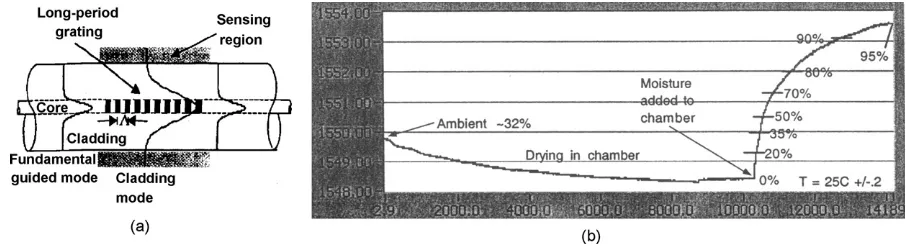
The use of LPGs for humidity sensing was first reported by
Luo et al.[63]from Luna Innovations, USA. In the sensor design
discussed and shown inFig. 13, carboxymethylcellulose (CMC)
hydrogel was covalently attached to cladding of a LPG to form the humidity sensor. The sensor demonstrated was found to oper-ate well over a humidity range from 0 to 95%, with a non-linear response dependency with humidity change. The sensor was observed to be unstable when it was fully saturated at condi-tions approaching 100%RH and temperature compensation was also required to obtain accurate humidity measurements. The sensor developed by Luna Innovations was evaluated on several separate occasions, as a moisture ingress sensor in aircraft lap
joints[64]and as a monitoring device for the moisture
detec-tion in building envelopes[65]. In both evaluations, promising
results were obtained, thus showing the potential of in-fibre grating-based humidity sensor in commercial/industrial based applications.
A similar LPG-based humidity sensing scheme was
demon-strated by Tan et al. [66] using a gelatine-coated LPG and
Konstantaki et al.[67]proposed a LPG humidity sensor utilising
polyethylene oxide (PEO)/CoCl2 hybrid overlay as the
mois-Fig. 12. (a) Experimental set-up used for moisture ingress rate measurement using FBG humidity sensors. (b) Sensor measurements showing moisture ingress characteristics of various concrete specimens using sensor positioned at 25 mm away from cube face[62].
[image:13.637.71.546.411.564.2] [image:13.637.74.527.605.728.2]Fig. 14. (a) Spectral characteristics of PVA-coated LPG at 1500 nm. (b) Transmission dip variation at various RH levels[68].
ture sensitive coating. In both sensors, however, the operating humidity range was found to be limited.
Recent studies by Venugopalan et al.[68] have shown the
use of polyvinyl alcohol (PVA) film as a sensing material for LPG-based humidity detection. Using a similar approach to the
examples discussed earlier, a PVA overlay of∼4m was coated
onto the optical fibre in which an LPG with a period of 300m
was inscribed. The sensor was evaluated over a relative humidity range from 33 to 97% using the resonance loss band at 1500 nm where the change in transmission dip was monitored and
cali-brated against humidity change. The results are shown inFig. 14:
the change of the spectral characteristics of the sensor with %RH leads to the calibration graph of resonance loss vs. %RH.
3.4. Interferometric sensors
Optical interferometry is a powerful and versatile tool that has been applied in optical fibre sensing to yield high perfor-mance FO sensors. In addition to the advantages attributed to the use of fibre optics, FO interferometric sensors generally provide geometric versatility in terms of sensor design and a high level
of measurement sensitivity[69]. The sensing mechanism relies
[image:14.637.76.513.69.227.2] [image:14.637.332.520.624.726.2]on the perturbation of the phase properties of the light signal travelling in the optical fibre introduced by an external environ-ment. The detection of the phase change is realised by mixing the signal of interest with a reference signal, consequently con-verting the phase difference between the two signals into an optical intensity change. Various interferometer configurations such as the Mach–Zehnder, Michelson, Sagnac and Fabry–Perot can be used to perform the detection. The operation of FO-based sensors utilising these configurations and its applications have been discussed in some detail by several authors including Udd
[70,71], Dandridge[69]and Mitchell[72].
One of the earliest FO interferometric humidity sensors was
demonstrated by Mitschke [73]. The proposed sensor design
consists of a thin film Fabry–Perot interferometer formed at the
tip of the optical fibre as shown in Fig. 12. The interference
between the optical signals reflected by the mirror at both ends of the cavity gives rise to a spectral response which gives a maximum intensity output (resonances) at specific wavelengths.
These multiple resonances are separated by the free spectral
range (λFSR) which is given by
λFSR= c
2nd (4)
wherecis the speed of light,nis the refractive index of the cavity
anddis the cavity length.
As shown inFig. 15, the Fabry–Perot cavity in the proposed
design was created by a layer of TiO2sandwiched in between
two partially reflecting mirrors, with the thickness of the cavity optimised to match the operation at the wavelength of the input diode laser source. As the refractive index of the cavity mate-rial has a dependence on humidity, the resonance was therefore shifted in response to humidity change and can be conveniently detected by performing intensity measurement at a fixed wave-length. The sensor demonstrated suffers from cross-sensitivity to temperature which can be corrected using a suitable compen-sation scheme. Nevertheless, it showed a good response between 0 and 80%RH and a response time of less than a minute.
Similar Fabry–Perot interferometric humidity sensors with a
submicron cavity length were reported by Arregui et al.[74,75]
and Yu et al.[76]. A typical multilayer thin film interferometric
cavity was formed by stacking bilayers of alternating cationic and anionic polymers at the fibre tip. This was achieved by using the ISAM technique which gives good control over the cavity length as well as the material composition of each coating layer. Sensors with a cavity length (or the number of bilayers) opti-mised at a specific operating wavelength were shown to be able to operate over a wide humidity range. A very fast response
time, in the order of less than a few seconds, was reported and the sensor has been recommended as a possible diagnostic tool
to monitor human breathing[77].
Kronenberg et al.[78]have explored the use of a low
coher-ence interferomertric system arranged in tandem configuration for humidity detection. The system consists of two Michel-son interferometers—(1) an interrogation system to perform the measurements and (2) a bi-fibre-optic sensor based on Michel-son configuration formed by a reference uncoated fibre and a hydrogel-coated fibre. In a similar way to the FBG sensing mech-anism described in the preceding section, the fibre sensor relies on humidity-induced swelling to stretch the fibres which in turn creates an interferometric sensor with an unbalanced path length.
4. Summary
The summary inTable 1has presented an overview of the
major work referenced in this review (using such data as are available from the publications) with in addition to the available information on the method and published data on the sensor to allow such cross-comparison and evaluation as is possible.
In this review, a variety of sensing techniques available to perform the measurement of humidity have been discussed. Fundamental and secondary methods involving mechanical, conventional optical, temperature and electronic-based tech-niques were discussed briefly, covering the key operating principles, as well as the advantages and disadvantages of each method. None of these methods, however, can offer an ‘ideal’ solution to address the various and specific requirements aris-ing from the diversity of potential applications seen in industry today. Fibre-optic sensing technology provides an alternative approach to moisture/humidity sensing as it offers several advan-tages over the use of conventional sensing methods. An extensive survey on various optical fibre sensing techniques employed for humidity detection of the work has been given in the later part of the review. The survey covered the various extrinsic and intrin-sic methods reported over the years, many of which report on the sensing characteristics obtained in a controlled laboratory environment. The field is one that is lively and topical, with applications, as has been discussed, in the structural monitoring and biomedical engineering fields in particular, reflecting the considerable scope for on-going work.
Acknowledgement
The authors are pleased to acknowledge the support of EPSRC in this work through various schemes.
References
[1] H. Arai, T. Seiyama, Humidity sensors, in: W. G ¨Opel, J. Hesse, J.N. Zemel (Eds.), Sensors: A Comprehensive Survey: Volume 3—Chemical and Biosensors, Part II, VCH, 1992.
[2] P.R. Wiederhold, Water Vapor Measurements, Marcel Dekker, 1997. [3] H.H. Willard, L.L. Merritt, J.A. Dean, F.A. Settle, Instrumental Methods
of Analysis, seventh ed., Wasworth Publishing Company, 1988. [4] C.Y. Lee, G.B. Lee, Humidity sensors: a review, Sens. Lett. 3 (2005) 1–14.
[5] Z. Chen, C. Lu, Humidity sensors: a review of materials and mechanisms, Sens. Lett. 3 (2005) 274–295.
[6] Z.M. Rittersma, Recent achievements in miniaturised humidity sensors—a review of transduction techniques, Sens. Actuators A 96 (2002) 196–210. [7] K. Tiefenthaler, W. Lukosz, Grating couplers as integrated optical humidity
and gas sensors, Thin Solid Films 126 (1985) 205–211.
[8] K.T.V. Grattan, T. Sun, Fibre optic sensor technology: an overview, Sens. Actuators A 82 (2000) 40–61.
[9] K.T.V. Grattan, B.T. Meggitt (Eds.), Optical Fiber Sensor Technology, Volume 4: Chemical and Environmental Sensing, Kluwer Academic Pub-lishers, 1999.
[10] G. Gauglitz, Opto-chemical and opto-immuno sensors, in: H. Baltes, W. Gopel, J. Hesse (Eds.), Sensors Update, vol. 1, VCH, 1996.
[11] Q. Zhou, M.R. Shahriari, D. Kritz, G.H. Sigel Jr., Porous fiber-optic sen-sor for high-sensitivity humidity measurements, Anal. Chem. 60 (1988) 2317–2320.
[12] S. Otsuki, K. Adachi, Humidity dependence of visible absorption spectrum of gelatin films containing cobalt chloride, J. Appl. Polym. Sci. 45 (1993) 1557–1564.
[13] F. Boltinghouse, K. Abel, Development of an optical relative humidty sen-sor. Cobalt chloride optical absorbency sensor study, Anal. Chem. 61 (1989) 1863–1866.
[14] S. Tao, C.B. Winstead, R. Jindal, J.P. Singh, Optical-fiber sensor using tailored porous sol–gel fiber core, IEEE Sens. J. 4 (2004) 322–328. [15] M. Ando, T. Kobayashi, M. Harutu, Humidity-sensitive optical absorption
of CO3O4film, Sens. Actuators B 32 (1996) 157–160.
[16] S. Otsuki, K. Adachi, T. Taguchi, A novel fiber-optic gas sensing arrange-ment based on an air gap design and an application to optical detection of humidity, Anal. Sci. 14 (1998) 633–635.
[17] Y. Sadaoka, M. Matsuguchi, Y. Sakai, Y. Murata, Optical humidity sens-ing characteristic of Nafion-dyes composite thin film, Sens. Actuators B 7 (1992) 443–446.
[18] T.E. Brook, M.N. Taib, R. Narayanaswamy, Extending the range of a fibre-optic relative humidity sensor, Sens. Actuators B 38–39 (1997) 272– 276.
[19] B. Kondratowicz, R. Narayanaswamy, K.C. Persaud, An investigation into the use of electrochromic polymers in optical fibre gas sensors, Sens. Actuators B 74 (2001) 138–144.
[20] J.P. Sharkany, S.O. Korposh, Z.I. Batori-Tarci, I.I. Trikur, J.J. Ramsden, Bacteriorhodopsin-based biochromic films for chemical sensors, Sens. Actuators B 107 (2005) 77–81.
[21] M.M.F. Choi, O.L. Tse, Humidity-sensitive optode membrane based on a fluorescent dye immobilised in gelatin film, Anal. Chim. Acta 378 (1999) 127–134.
[22] H.E. Posch, O.S. Wolfbeis, Fibre-optic humidity sensor based on fluores-cence quenching, Sens. Actuators 15 (1988) 77–83.
[23] A. Raichur, H. Pedersen, Fiber optic moisture sensor for baking and drying process control, proc. food processing automation iV, Am. Soc. Agric. Eng. (1995) 180–189.
[24] D.B. Papkovsky, G.V. Ponomarev, S.F. Chernov, A.N. Ovchinnikov, I.N. Kurochkin, Luminescence lifetime-based sensor for relative air humidity, Sens. Actuators B 22 (1994) 57–61.
[25] S.J. Glenn, B.M. Cullum, R.B. Nair, D.A. Nivens, C.J. Murphy, S.M. Angel, Lifetime-based fiber-optic water sensor using a luminescent complex in a lithium-treated Nafion membrane, Anal. Chim. Acta 448 (2001) 1–8. [26] J.M. Costa-Fernandez, M.E. Diaz-Garcia, A. Sanz-Medel, A critical
comparision of different to develop room temperature phosphorescence sensing phases of air moisture, Sens. Actuators B 35–39 (1997) 103– 109.
[27] M. Bedoya, M.T. Diez, M.C. Moreno-Bondi, G. Orellana, Humidity sens-ing with a luminescent Ru(II) complex and phase-sensitive detection, Sens. Actuators B 113 (2006) 573–581.
[28] J.C. Palais, Fiber Optic Communications, fifth ed., Prentice Hall, 2005 (Chapter 5).
[29] J.P. Dakin, B. Culshaw, Optical Fiber Sensors: Principles and Components, Artech House, 1988.
4: Chemical and Environmental Sensing, Kluwer Academic Publishers, 1999.
[31] B.D. MacCraith, Optical fiber chemical systems and devices, in: K.T.V. Grattan, B.T. Meggitt (Eds.), Optical Fiber Sensor Technology, Volume 4: Chemical and Environmental Sensing, Kluwer Academic Publishers, 1999. [32] A.P. Russell, K.S. Fletcher, Optical sensor for the determination of
mois-ture, Anal. Chim. Acta 170 (1985) 209–216.
[33] D.S. Ballantine, H. Wohltjen, Optical waveguide humidity detector, Anal. Chem. 58 (13) (1986) 2883–2885.
[34] A. Kharaz, B. Jones, A distributed fibre optic sensing system for humidity measurement, Meas. Contr. 28 (1995) 101–103.
[35] A. Kharaz, B.E. Jones, K.F. Hale, L. Roche, K. Bromley, Optical fibre relative humidity sensor using a spectrally absorptive material, in: SPIE Proceedings of International Conference on Optical Fiber Sensors, vol. 4185, Venice, Italy, 2000, pp. 370–373.
[36] R. Jindal, S. Tao, J.P. Singh, P.S. Gaikwad, High dynamic range fiber optic relative humidity, Opt. Eng. 41 (5) (2002) 1093–11093.
[37] S.K. Khijwania, K.L. Srinivasan, J.P. Singh, Performance optimised fiber sensor for humidity measurement, Opt. Eng. 44 (3) (2005) 034401-1–034401-7.
[38] S. Otsuki, K. Adachi, T. Taguchi, A novel fiber optic gas sensing con-figuration using extremely crived optical fibers and an attempt for optical humidity detection, Sens. Actuators B 53 (1998) 91–96.
[39] B.D. Gupta, Ratnanjali, A novel probe for a fiber optic humidity sensor, Sens. Actuators B 80 (2001) 132–135.
[40] S.K. Shukla, G.K. Parachar, A.P. Mishra, P. Misra, B.C. Yadav, R.K. Shukla, L.M. Bali, G.C. Dubey, Nano-like magnesium oxide films and its sig-nificance in optical fiber humidity sensor, Sens. Actuators B 98 (2004) 5–11.
[41] S. Muto, O. Suzuki, T. Amano, M. Morisawa, A plastic optical fibre sensor for real-time humidity monitoring, Meas. Sci. Technol. 14 (2003) 746–750. [42] F.J. Arregui, Z. Ciaurriz, M. Oneca, I.R. Matias, An experimental study about hydrogels for the fabrication of optical fiber humidity sensors, Sens. Actuators B (2003).
[43] C. Bariain, I.R. Matias, F.J. Arregui, M. Lopez-Amo, Optical fiber humidity sensor based on a tapered fiber coated with agarose gel, Sens. Actuators B 69 (2000) 127–131.
[44] J.M. Corres, J. Bravo, I.R. Matias, Nonadiabatic tapered single-mode fiber coated with humidity sensitive nanofilms, IEEE Photonics Technol. Lett. 18 (8) (2006) 935–937.
[45] J.M. Corres, J. Bravo, I.R. Matias, Sensitivity optimisation of tapered optical fiber humidity sensors by means of tuning the thickness of nanos-tructured sensitive coatings, Sens. Actuators B (2006).
[46] A. Gaston, I. Lozano, F. Perez, F. Auza, J. Sevilla, Evanescent wave optical-fiber sensing (temperature, relative humidity and pH sensors), IEEE Sens. J. 3 (6) (2003) 806–811.
[47] A. Gaston, F. Perez, J. Sevilla, Optical fiber relative humidity sensor with polyvinyl alcohol film, Appl. Opt. 43 (21) (2004) 4127–4132.
[48] A. Alvarez-Herrero, H. Guerrero, D. Levy, High-sensitivity sensor of a low relative humidity based on overlay on side-polished fibers, IEEE Sens. J. 4 (1) (2004) 52–56.
[49] K. Ogawa, S. Tsuchiya, H. Kawakami, Humidity sensing effects of optical fibers with microporous SiO2cladding, Electron. Lett. 24 (1) (1988) 42–43.
[50] L. Xu, J.C. Fanguy, K. Soni, S. Tao, Optical fiber humidity sensor based on evaenscent wave scattering, Opt. Lett. 29 (11) (2004) 1191–1193. [51] A. Othonos, Bragg gratings in optical fibers: fundamentals and applications,
in: K.T.V. Grattan, B.T. Meggitt (Eds.), Optical Fiber Sensor Technology, Kluwer Academic Publishers, Boston, 2000.
[52] Y.J. Rao, Recent progress in applications of in-fibre bragg grating sensors, Opt. Lasers Eng. 31 (1999) 297–324.
[53] S.W. James, R.P. Tatam, Optical fibre long-period grating sensors: charac-teristics and application, Meas. Sci. Technol. 14 (2003) R49–R61. [54] B. Sutapun, M. Tabib-Azar, A. Kazemi, Pd-coated elastooptic fiber optic
Bragg grating sensors for multiplexed hydrogen sensing, Sens. Actuators B 60 (1999) 27–34.
[55] J. Cong, X. Zhang, K. Chen, J. Xu, Fiber optic bragg grating sensor based on hydrogels for measuring salinity, Sens. Actuators B 87 (2002) 487– 490.
[56] P. Giaccari, H.G. Limberger, P. Kronenberg, Influence of humidity and tem-perature on polyimide-coated fiber Bragg gratings, in: Proceedings OSA Trends in Optics and Photonics Series: Bragg Gratings, Photosensitivity, and Poling in Glass Waveguides, vol. 61, Washington, DC, USA, 2001, p. BFB2.
[57] P. Kronenberg, P.K. Rastogi, P. Giaccari, H.G. Limberger, Relative humid-ity sensor with optical fiber Bragg grating, Opt. Lett. 27 (2002) 1385– 1387.
[58] T.L. Yeo, T. Sun, K.T.V. Grattan, D. Parry, R. Lade, B.D. Powell, Character-isation of a polymer-coated fibre Bragg grating sensor for relative humidity sensing, Sens. Actuators B 110 (2005) 148–156.
[59] M. Laylor, S. Calvert, T. Taylor, W. Schulz, R. Lumsden, E. Udd, Fiber optic grating moisture and humidity sensors, in: Proceedings Smart Structures And Materials: Smart Sensor Technology & Measurement System, vol. 4694, San Diego, CA, USA, 2002, pp. 210–217.
[60] W. Kunzler, S. Calvert, M. Laylor, Measuring humidity & moisture with fiber optic sensors, in: Proceedings Sixth Pacific Northwest Fiber Optic Sensor Workshop, vol. 5278, Oregon, USA, 2003, pp. 86– 93.
[61] T.L. Yeo, D. Eckstein, B. McKinley, L.F. Boswell, T. Sun, K.T.V. Grattan, Demonstration of a fibre optic sensing technique for the measurement of moisture absorption in concrete, Smart Mater. Struct. 15 (2006) N40–N45. [62] T.L. Yeo, M.A.C. Cox, L.F. Boswell, T. Sun, K.T.V. Grattan, Optical fiber sensor for monitoring ingress of moisture in concrete structure, Rev. Sci. Instrum. 77 (2006) 055108-1–055108-7.
[63] S. Luo, Y. Liu, A. Sucheta, M. Evans, R. van Tassell, Applications of LPG fiber optical sensors for relative humidity and chemical warfare agents monitoring, in: Proceedings Advanced Sensor Systems and Applications, vol. 4920, 2002, pp. 193–204.
[64] K.R. Cooper, Y. Ma, J.P. Wikswo, R.G. Kelly, Simultaneous monitoring of the corrosion activity and moisture inside aircraft lap joints, Corros. Eng. Sci. Technol. 39 (2004) 339–345.
[65] W.M. Healy, S. Luo, M. Evans, A. Sucheta, Y. Liu, Development of an optical fiber-based moisture sensor for building envelopes, in: Proceedings 24th AIVC Conference and BETEC Conference on Ventilation, Humidity Control and Energy, 2003, pp. 277–282.
[66] K.M. Tan, C.M. Tay, S.C. Tjin, C.C. Chan, H. Rahardjo, High relative humidity measurements using gelatin coated long-period grating sensors, Sens. Actuators B 110 (2005) 335–341.
[67] M. Konstantaki, S. Pissadaki, S. Pispas, N. Madamopoulous, N.A. Vainos, Optical fiber long period grating humidity sensor with PEO/CoCl2coating,
Appl. Opt. 45 (2006) 4567–4571.
[68] T. Venugopalan, T.L. Yeo, T. Sun, K.T.V. Grattan, LPG based PVA coated sensor for relative humidity measurement, in: Proceedings Third European Workshop on Optical Fibre Sensors, vol. 6619, Napoli, Italy, 2007, pp. 661925-1–661925-4.
[69] A. Dandridge, Fiber optic sensors based on the Mach-Zehnder and Michel-son interferometers, in: E. Udd (Ed.), Fiber Optic Sensors: An Introduction for Engineers and Scientists, John Wiley & Sons, 1991.
[70] E. Udd, An overview of fiber-optic sensors, Rev. Sci. Instrum. 66 (1995) 4015–4030.
[71] E. Udd, Fiber optic sensors based on the Sagnac interferometer and passive ring resonator, in: E. Udd (Ed.), Fiber Optic Sensors: An Introduction for Engineers and Scientists, John Wiley & Sons, 1991.
[72] G.L. Mitchell, Intensity-based and fabry-perot interferometer sensors, in: E. Udd (Ed.), Fiber Optic Sensors: An Introduction for Engineers and Scientists, John Wiley & Sons, 1991.
[73] F. Mitschke, Fiber optic sensor for humidity, Opt. Lett. 14 (7) (1989) 967–969.
[74] F.J. Arregui, Y. Liu, I.R. Matias, R.O. Claus, Optical fiber humidity sensor using a nano Fabry–Perot cavity formed by the ionic self-assembly method, Sens. Actuators B 59 (1999) 54–59.
[75] F.J. Arregui, K.L. Cooper, Y. Liu, I.R. Matias, R.O. Claus, Optical fiber humidity sensor with a fast response time using the ionic self-assembly method, IEIEC Trans. Electron. E83C (3) (2000) 360–365.
[77] Q. Chen, R.O. Claus, W.B. Spillman, F.J. Arregui, I.R. Matias, K.L. Cooper, Optical fiber sensors for breathing diagnostic, in: Proceedings OFS 15, vol. 1, Portland, Oregon, USA, 2002, pp. 273–276.
[78] P. Kronenberg, B. Culshaw, G. Pierce, Development of a novel fiber optic sensor for humidity monitoring, in: Proceedings SPIE Conference on Sen-sory Phenomena and Measurement Instrumentation for Smart Structures and Materials, 1999, pp. 480–485.
Biographies
T.L. Yeoreceived his BEng degree from the Department of Electrical Engi-neering and Electronics, University of Manchester Institute of Science and Technology (UMIST), UK, in 2000. Following the successful application for the Overseas Research Studentship (ORS), he obtained his MPhil degree in fluorescence based fibre optic probe for hydrocarbon fuel monitoring with the industrial process tomography group at UMIST in 2002. He completed his PhD in the field of fibre optic sensors at City University, London, in 2007.
T. Sunwas awarded the degrees of Bachelor of Engineering, Master of Engi-neering and Doctor of EngiEngi-neering for work in mechanical engiEngi-neering from the Department of Precision Instrumentation of Harbin Institute of Technology, Harbin, China, in 1990, 1993 and 1996, respectively. She came to City Univer-sity, London, as an Academic Visitor and latterly a research fellow to work in the field of fibre optic temperature measurement using luminescent techniques. She was awarded the degree of Doctor of Philosophy at City University in applied physics in 1999. She was an assistant professor at Nanyang Technological Uni-versity in Singapore from 2000 to 2001 and currently a senior lecturer at City University, London, since she re-joined in April 2001. Dr. Sun is a Member of the Institute of Physics and the Institution of Electrical Engineers and a
Char-tered Physicist and a CharChar-tered Engineer in the United Kingdom. Her research interest is in optical fibre sensors, optical communications and laser engineering. She has authored or co-authored some 90 scientific and technical papers in the field.


![Fig.3. SEMpictureoftheporoussol–gelsilicafibre,showingtheinterconnectedporous structure on the surface of the fibre [14].](https://thumb-us.123doks.com/thumbv2/123dok_us/1636998.117042/7.637.153.457.553.728/fig-sempictureoftheporoussol-gelsilicabre-showingtheinterconnectedporous-structure-surface-bre.webp)
![Fig. 6. Optical responses of distributed fibre-optic sensing system using optical time domain reflectometer (OTDR) [34].](https://thumb-us.123doks.com/thumbv2/123dok_us/1636998.117042/9.637.315.562.644.719/optical-responses-distributed-bre-sensing-optical-domain-reectometer.webp)

![Fig. 11. (a) Schematic of a polymer-coated FBG sensor for soil moisture sensing. (b) Data showing evaporation rate of soil samples with various moisture content[60].](https://thumb-us.123doks.com/thumbv2/123dok_us/1636998.117042/12.637.78.504.596.718/schematic-polymer-moisture-sensing-evaporation-samples-moisture-content.webp)