MICROSTRUCTURAL EVALUATION OF COLD SPRAY DEPOSITED
WC WITH SUBSEQUENT FRICTION STIR PROCESSING
Tom Peat1, Alexander Galloway1, Tiziana Marrocco2, Naveed Iqbal2
1
University of Strathclyde, 16 Richmond St, Glasgow, G1 1XQ, United Kingdom
2
TWI, Wallis Way, Catcliffe, Rotherham, South Yorkshire S60 5TZ, United Kingdom
Keywords: Cold Spray, Friction Stir Processing, Aluminium, Hardness, Microstructure
Abstract
Friction Stir Processing (FSP) has been shown to improve the strength, ductility and toughness of both aluminium and steel materials through grain refinement and the even distribution of precipitates within the substrate matrix. This article presents the application of FSP of Cold Spray deposited Tungsten Carbide – Cobalt (WC-Co) of two distinct types, on a series of aluminium substrates. Microstructural investigations of FSP processed samples exhibit interaction between the deposited WC-Co particles and aluminium alloy and show the homogeneous dispersion of deposited particles through the metal matrix. Results show that the dispersion of these particles varies with powder type, FSP parameters and substrate characteristics. A parallel study focusing on the hardness of the FSP generated Metal Matrix Composite (MMC) further demonstrate the potential of combining Cold Spray and FSP technologies to tailor surface properties for specific applications.
Introduction
Friction Stir Processing (FSP) is a variant of the widely adopted Friction Stir Welding (FSW) process used to carry out solid state welding of a variety of metals and alloys. FSP makes use of a rotating tool that is plunged into a chosen substrate. The heat generated as a result of friction, causes the substrate to plastically deform with the rotation of the tool forcing material from the leading edge round to the rear of the tool. Details of the FSP process can be found elsewhere, [1] [2] [3] [4], but the beneficial features of the process include substantial grain refinement and homogeneous distribution of impurities and precipitates throughout the metal matrix, both of which lead to improvements in the mechanical properties of the material [5] [6].
The present study is a highly novel preliminary assessment that considers the effect of CS deposited WC-Co, combined with subsequent FSP. The microstructure and hardness are evaluated for a variety of substrate and coating combinations. Limited data exists in the area of combined CS deposition and FSP. Previously, Hodder et al [10] have reported the co-deposition of Al and Al2O3 onto AA6061 Al alloy with the aim of investigating the influence
of Al2O3 content on the coating following stirring. Hodder found that homogenous
distribution of the hard Al2O3 particles within the MMC lead to increased hardness, with a
reduction in the mean free particle distance of the Al2O3 particles below a distance of 5m
resulting in the greatest hardness increase. The aim of the present study is to investigate the effect of varying FSP tool geometry, coating type and substrate material on the microstructure and mechanical properties of the modified surface. The results from this study will form an initial insight to evaluate the interaction between deposited coating and substrate following FSP and develop a pathway for further research in this area.
Experimental Procedure
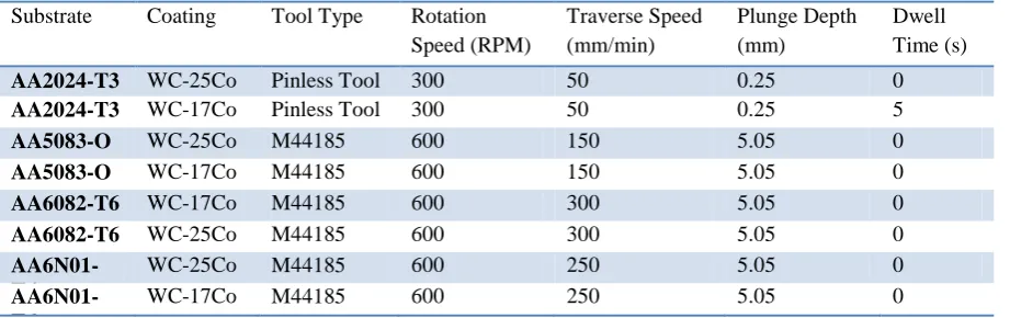
CS deposition was carried out using a CGT Kinetics 4000/47 CS system, connected to a PF 4000 Comfort series powder feeder operating at a powder feed rate of 3.5rpm. The carrier gas used to accelerate the powder particles was nitrogen and operated at a pressure of 30Bar for all WC-Co coatings. The CS apparatus was mounted to an OTC 6 axis robotic arm to increase repeatability and reproducibility of results. The spray gun was fitted with a long pre-chamber to increase the nozzle exit temperature of the powder to around 700oC. An iterative approach was used to determine the most appropriate stand-off distance and traverse speed, with a series of test coupons being sprayed with varying parameters. The stand-off distance between the substrate and nozzle was set to 50mm, with the nozzle traversing horizontally across the substrate at a speed of 50mm/s. It was found that further reducing the stand-off distance resulted in a shot blasting affect, with very little powder adhering to the substrate. In order to provide a suitably large coated area for subsequent FSP, eight passes were carried out, with an overlap of 2mm. This gave a total track width of 50mm. The two WC-Co powders used in the study have distinct internal structures. WC-17Co powder is comprised of nano scale Tungsten Carbides, evenly distributed throughout a Cobalt matrix [11]. WC-25Co is comprised of a Tungsten Carbide core surrounded by a Cobalt binder. The diameter of powder particles lies between 5µm and 30µm. The CS system was used to deposit the two powder types onto four aluminium substrates. Each test plate measured 200mm by 120mm by 3mm. Test plates were degreased using acetone prior to CS deposition. Table 1 outlines the FSP parameters that were applied to the coated specimens and the specific alloy grades assessed.
Substrate Coating Tool Type Rotation Speed (RPM) Traverse Speed (mm/min) Plunge Depth (mm) Dwell Time (s)
AA2024-T3 WC-25Co Pinless Tool Steel
300 50 0.25 0
AA2024-T3 WC-17Co Pinless Tool Steel
300 50 0.25 5
AA5083-O WC-25Co M44185 600 150 5.05 0
AA5083-O WC-17Co M44185 600 150 5.05 0
AA6082-T6 WC-17Co M44185
(PCBN SN 1871)
600 300 5.05 0
AA6082-T6 WC-25Co M44185
(PCBN SN 1871)
600 300 5.05 0
AA6N01-T6
WC-25Co M44185
(PCBN SN 1871)
600 250 5.05 0
AA6N01-T6
WC-17Co M44185
(PCBN SN 1871)
[image:2.595.67.528.597.742.2]600 250 5.05 0
As FSP tool design is crucial to producing a high quality stirred zone, two tool types were investigated. The first being a pinless tool with fixed shoulder comprised of concentric circular features, manufactured from tool steel, the second being an MS-M-005 PCBN tool with 5mm pin length and a fixed shoulder with concentric circular features. The 5mm pin also featured a spiral pattern to force material from the surface down to the root of the stir zone.
The following testing programme was conducted to achieve the outcomes of this study:
Optical Microscopy: to establish the interaction, (if any), between deposited coating and substrate. Evaluate the distribution of deposited coating through the substrate. Images were taken using an Olympus G51X series optical microscope.
Scanning Electron Microscopy (SEM): To verify images obtained from optical microscopy and to identify the elements present within the MMC. WC-Co content was quantified by taking SEM images at prescribed locations and carrying out Energy-dispersive X-ray spectroscopy (EDX) analysis. Hitachi S-3000N VP-SEM series Scanning Electron Microscope (SEM) with EDX used to carry out analysis.
Micro-hardness measurement: To establish the hardness at various locations within the stir zone. Mitutoyo MVK-G1 micro-hardness tester was used to evaluate hardness with a 200gf load.
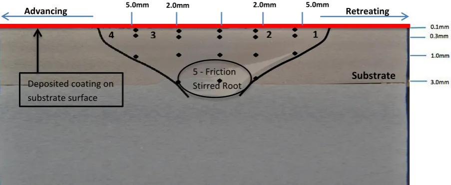
[image:3.595.75.527.487.673.2] The areas assessed are outlined in Figure 1 with the locations kept consistent throughout all analysis.
Figure 1 displays the cross section of a friction stir processed region. Numbers 1-4 signify the locations in which optical and electron microscopy were carried out with number 5 denoting the friction stirred root region. The advancing side and retreating side of the stir zone have also been indicated. It should be noted that the advancing side and retreating side on samples W30 and W31 are reversed due to the rotation of the pinless tool being opposite to that of the PCBN tool.
Figure 1 – Cross section of FSP friction stir region showing the hardness indent locations and locations of optical and SEM images.
1 2
4 3
Deposited coating on substrate surface
Substrate
Retreating Advancing
5 - Friction Stirred Root
Results
Table 2 outlines the nomenclature adopted to describe individual specimen corresponding to a particular coating and substrate combination.
Specimen Code
Substrate Coating
W30 AA2024-T3 WC-25Co
W31 AA2024-T3 WC-17Co
W41 AA5083-O WC-25Co
[image:4.595.71.525.411.640.2]W44 AA5083-O WC-17Co
Table 2 – Sample coding system.
Specimen Code
Substrate Coating
W50a AA6082-T6 WC-17Co
W50b AA6082-T6 WC-25Co
W54a AA6N01-T6 WC-25Co
W54b AA6N01-T6 WC-17Co
Optical Microscopy
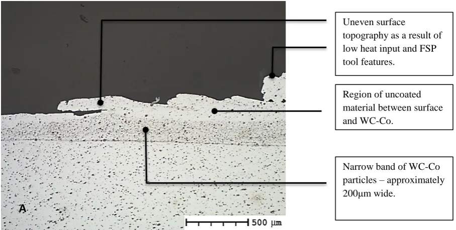
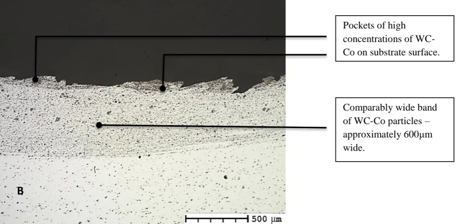
Optical microscopy was employed for initial assessment to determine whether CS deposited particles had been successfully embedded into the substrate during FSP processing, or simply removed by the FSP tool. Figure 3 exhibits a magnified region of the top surface of sample W31, showing a larger concentration of WC-Co particles, compared to that seen in W30. This suggests that the amount of WC-Co coating present in W31 is greater than that found in W30. A comparison of both images reveals that W31 exhibits a more homogeneous layer of embedded particles, with the WC-Co regions present in W30 being relatively inconsistent in size and shape.
A
Narrow band of WC-Co particles – approximately 200μm wide.
Uneven surface
topography as a result of low heat input and FSP tool features.
Figure 3 – Micrographs displaying advancing side of A) Specimen W30 B) W31 located in region 2 from Figure 1, prepared to a 1m finish. [x50 Unetched]
Previous studies have shown that the heat input to the stir zone relates to the plasticity of the substrate material [12]. Based on this, the 5s dwell time during FSP of sample W31 has increased the heat in the FSP region, thereby increasing the plasticity of the substrate alloy. This, in turn has permitted a greater quantity of the coating to be embedded into the softer substrate. It is likely that particle morphology has also influenced the particle flow behaviour during FSP, and has affected the distribution pattern seen in the substrate material. The nano scale carbides within the Cobalt matrix in WC-17Co could permit the larger (≈200m) particles to break down more easily and embed within the substrate. It is important to highlight that despite the differences between the two samples, both exhibit significant interaction and mixing between the coating and substrate. The next series of images refer to the specimens processed using the 5mm PCBN tool. Figure 4 shows magnified images of region 3 in specimens W50a and W50b, with Figure 5 exhibiting the stir root for specimens W54a and W54b.
B
A
Regions of finely dispersed coating showing significant size reduction.
Unaffected WC-Co particles embedded throughout Al matrix. Comparably wide band of WC-Co particles – approximately 600μm wide.
Figure 4 – Micrographs of A) Specimen W50a, B) Specimen W50b taken at Location 3 from Figure 1, prepared to a 1m finish. [x50 Unetched]
Specimen W50b exhibits a homogeneous distribution of particles along the top surface of the substrate, whereas W50a contains large, (≈200m) particles that are present throughout the stir zone. Given that both samples were stirred using the same tool, and identical FSP parameters, it is likely the variation in particle morphology and their distinct flow behaviours in plasticized aluminium during processing, has resulted in this distinct difference in microstructure.
Tool traverse speed was reduced to 250mm/min for samples W54a and W54b, with all other parameters kept consistent with previous samples. In doing so, the heat input into the sample is increased. A by-product of this increased heat is increased plasticity in the stir region, which can potentially permit greater flow of the deposited coating particles. This feature of material flow was investigated by Thangarasu et al; and demonstrated that an increase in the traverse speed leads to an increase in micro hardness [13].
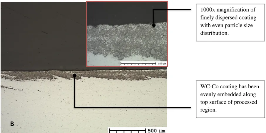
B
A
1000x magnification of finely dispersed coating with even particle size distribution.
WC-Co coating has been evenly embedded along top surface of processed region.
High magnification reveals only slight variation in particle size.
WC-Co particles following the flow pattern of plasticised substrate down to the stir root.
Figure 5 – Friction Stir root (Figure 1) comparison for A) Specimen W54a, B) Specimen W54b. [x50 Unetched]
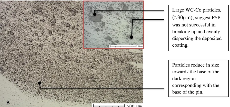
Assessment of microstructure at locations 2 and 3 of specimens W54a and W54b showed significantly less WC-Co particles at the surface when compared to that seen in Figure 4, with the quantity of coating particles varying significantly between the advancing and the retreating sides. However, as shown in Figure 5, large quantities of WC-Co particles were present at the root of the stir zone in both specimens. Though heat input has potentially caused more of the coating particles to flow down towards the root of the stir zone, the varied material flow patterns of different aluminium alloy substrates, even with similar FSP tool and process conditions, needs to be considered and may well determine the distribution pattern of coating particles within the substrate. Moreover, particle size also reduces towards the base of the pin, which aligns with the area exposed to the highest shear forces [14]. The results from specimens W54a and W54b also corroborate those found in W50a and W50b in relation to the breakup of powder particles. Although not shown within this report, similar studies on specimens W41 and W44 again showed that coating WC-25Co is more easily broken down and dispersed through the substrate.
EDX Analysis
Using SEM, EDX analysis was performed to assess the elements present within the stir zone. Table 3 illustrates the results from the EDX analysis of various locations within the specimens. A diagram showing the assessed locations can be seen in Figure 1.
Spectrum O Mg Al Mn Co Cu W Total
Sample I.D. Location
W31 1 0 1.21 83.25 0.63 1.07 5.29 8.56 100
W31 2 0 1.25 85.73 0.55 0.95 5.17 6.35 100
W31 3 0 1.15 80.83 0.63 1.67 4.52 11.18 100
W31 4 1.81 1.2 81.43 0.55 1.19 4.92 8.89 100
W50b 2 0 0.52 63.27 0 5.44 0.48 30.29 100
W50b 3 0 0.5 62.9 0 4.67 0.56 31.31 100
W50b 5 0 0.48 89.08 0.54 0.93 0.7 8.28 100
W54a 2 0 0.53 85.56 0 1.89 0 12.02 100
B
Large WC-Co particles,
(≈30m), suggest FSP was not successful in breaking up and evenly dispersing the deposited coating.
Particles reduce in size towards the base of the dark region –
[image:7.595.76.525.71.281.2] [image:7.595.70.503.617.761.2]W54a 3 0 0.53 69.63 0 4.84 0 25 100
[image:8.595.67.507.72.105.2]W54a 5 0 0.48 75.91 0 2.88 0.63 20.1 100
Table 3 – EDX analysis of FSP regions.
The results indicate a distribution pattern of W and Co particles across the width of each stir zone, with a slight reduction in weight % observed in the retreating sides of W31 and W50b, with a significant reduction observed in W54a. This variation in elemental distribution is a potential consequence of reduced frictional heating, observed in the retreating side of the tool. The impact of tool design on the distribution of coating particles is also evident through relative comparison of sample W31, produced using a pinless tool, with samples W50b and W54a, produced using the PCBN tool. Higher heat input due to higher tool rotation speed, resulting in increased plasticity is also an important factor in increasing the quantity of WC-Co in the Al matrix.
Hardness
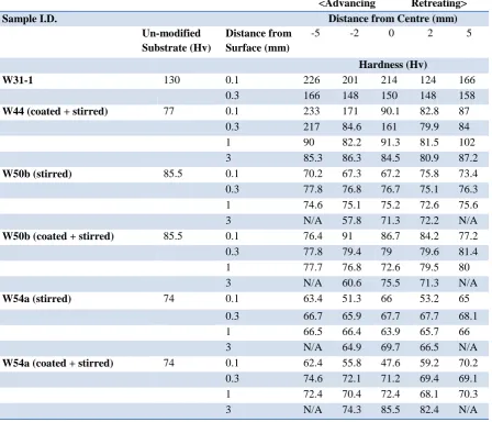
Micro hardness measurements were taken for the FSP processed region with and without deposited coating, along with unaltered substrate. The results of these measurements can be seen in Table 4, with the location of hardness intends being outlined in Figure 1.
<Advancing Retreating>
Sample I.D. Distance from Centre (mm)
Un-modified Substrate (Hv)
Distance from Surface (mm)
-5 -2 0 2 5
Hardness (Hv)
W31-1 130 0.1 226 201 214 124 166
0.3 166 148 150 148 158
W44 (coated + stirred) 77 0.1 233 171 90.1 82.8 87
0.3 217 84.6 161 79.9 84 1 90 82.2 91.3 81.5 102 3 85.3 86.3 84.5 80.9 87.2
W50b (stirred) 85.5 0.1 70.2 67.3 67.2 75.8 73.4
0.3 77.8 76.8 76.7 75.1 76.3 1 74.6 75.1 75.2 72.6 75.6 3 N/A 57.8 71.3 72.2 N/A
W50b (coated + stirred) 85.5 0.1 76.4 91 86.7 84.2 77.2
0.3 77.8 79.4 79 79.6 81.4 1 77.7 76.8 72.6 79.5 80 3 N/A 60.6 75.5 71.3 N/A
W54a (stirred) 74 0.1 63.4 51.3 66 53.2 65
0.3 66.7 65.9 67.7 67.7 68.1 1 66.5 66.4 63.9 65.7 66 3 N/A 64.9 69.7 66.5 N/A
W54a (coated + stirred) 74 0.1 62.4 55.8 47.6 59.2 70.2
0.3 74.6 72.1 71.2 69.4 69.1 1 72.4 70.4 72.4 68.1 70.3 3 N/A 74.3 85.5 82.4 N/A
[image:8.595.70.519.354.738.2]Results indicate that samples W31 and W44 exhibit a significant increase to hardness post FSP processing, in regions with a high weight % of WC-Co. Specimens W50 and W54, however, exhibit a drop in hardness when compared to the parent substrate. Given the elevated temperature associated with the high rotation speeds in these samples, it is likely this has had a softening effect on the hardened, T6, condition. This softened matrix is incapable of supporting the hard WC-Co particles under load and as a result, the hard phase particles have little impact on the hardness of the matrix, even in regions of high coating density, i.e. the stir zone root. Despite this, the non-heat treated alloy, AA5083-O responded well to the process – showing an increase in hardness of over 200% in one location.
Conclusion
The hardness of AA6XXX-T6 alloys decreases with FSP. The high heat input results in an annealing effect of the hardened condition.
The AA2024-T3 alloy shows an increase to hardness of around 43%, after FSP of CS deposited WC-Co coating.
The AA5083-O alloy demonstrated significant hardness increase of over 200% after FSP of CS deposited WC-Co coatings
When compared to pinless tool geometry, the PCBN tool promotes greater mixing and increases weight % of WC-Co embedded within the Al matrix due to the higher rotation speeds and addition of the 5mm spiral pin.
Specimens produced using the PCBN tool demonstrate that WC-25Co experiences a higher level of particle size reduction compared with WC-17Co. This confirms that powder morphology has a significant effect on the resultant MMC.
References
[1] H. Krohn, R.M. Miranda, P. Vilca, L. Quintino, J.F. dos Santos J. Gandra, "Friction Surfacing - A Review," Journal of Materials Processing Technology, (2013). [2] Devinder Yadav, G. Suhas Ranjit Bauri, "Effect of friction stir processing (FSP) on
microstructure and properties of Al–TiC in situ composite," Materials Science and Engineering , vol. 528, no. 13-14, (May 2011), pp. 4732–4739.
[3] M.L. Santella et al, "Effects of friction stir processing on mechanical properties of the cast aluminium alloys A319 and A356," Scripta Materialia vol. 53, (2005).
[4] João Gandra, "Friction stir processing," Surface Modification by Solid State Processing, pp. 73-111, (2014).
[5] C.J. Lee, J.C. Huang C.I. Chang, "Relationship between grain size and Zener–Holloman parameter during friction stir processing in AZ31 Mg alloys ," Scripta Materialia , vol. 51, (May 2004), pp. 509-514.
[6] Huijie Liua, Sudarsanam Suresh Babu Xiuli Feng, "Effect of grain size refinement and precipitation reactions on strengthening in friction stir processed Al–Cu alloys," Scripta Materialia, 65, (September 2011), pp. 1057-1060.
[7] V. Kosarev, K.V. Klinkov, A. Alkhimov, V.M.Formin A. Papyrin, Cold Spray Technology. Oxford: Elsevier, (2006).
[8] E.R. Nivinski B.A. Kushner, "Thermal Spray Coatings," vol. 18, (1992).
[10] H Izadi, AG McDonald, A.P. Gerlich K.J. Hodder, "Fabrication of aluminium-alumin metal matrix composites via cold gas dynamic spraying at low pressure followed by friction stir processing," Materials Science & Engineering, vol. 556, (2012), pp. 114-121. [11] , Xiao Chen a,b, Xiao-Bo Bai a,b, Gang-Chang Ji a,b,⁎, Zeng-Xiang Dong a,b,
Deng-Liang Yi a Hong-Tao Wang a, "Microstructure and properties of cold sprayed
multimodal WC–17Co deposits," Int. Journal of Refractory Metals and Hard Materials, vol. 45, (July 2014), pp. 196-203.
[12] Y. Miyamoto, Y. Watanabe, Y. Natio, T. Nose H. Sato, "Fragmentation behavior of Al3Ti particles in Al-Al3Ti composite deformed by friction stir processing,"
Proceedings of the 1st International Joint Symposium on Joining and Welding , vol. 1, (November 2013), pp. 453-457.
[13] N. Muruganb, I. Dinaharanc, S.J. Vijayd A. Thangarasua, "Influence of Traverse Speed on Microstructure and Mechanical Properties of AA6082-TiC Surface Composite Fabricated by Friction Stir Processing," Procedia Materials Science, vol. 5, (2014), pp. 2115-2121.
[14] Ehab A. El-Danafa Magdy M. El-Rayesa, "The influence of multi-pass friction stir processing on the microstructural and mechanical properties of Aluminum Alloy 6082,"
Journal of Materials Processing Technology, vol. 212, no. 5, (May 2012), pp. 1157-1168.
[15] M. Saadatmand, J. Aghazadeh Mohandesi, M. Salehi, "Optimization of process parameters for producing AA6061/SiC nanocomposites by friction stir processing,"