Medium density control for coal washing dense
medium cyclone circuits
Lijun Zhang, Xiaohua Xia, Jiangfeng Zhang
Abstract—The dense medium cyclone (DMC) process used in coal beneficiation plants is studied from a control system perspective. Employing the dynamic model of the DMC process based on mass flow balance, a model based control strategy is proposed. The controller adjusts the density of medium used to enhance separation in the DMC process according to measurements on percentages of different components in raw coal. The first objective of the control is to maintain the carbon content in the clean coal to a set level. The second purpose is to minimize energy consumption of the DMC process in view of the fast increasing electricity price. The controller solves an optimisation problem formulated to determine the density of medium whenever new measurements are available. Both coal quality and DMC operational constraints are account for. Simulations, based-on measured plant data, are carried out to verify the feasibility and effectiveness of the control strategy designed. The results show that the designed controller is able to fulfill its purpose satisfactorily when the characteristics of the raw coal varies and when measurement uncertainties are in presence.
Index Terms—Optimal control, dense medium cyclone, coal beneficiation, density control.
I. INTRODUCTION
Run-of-mine (ROM) coal has different impurities such as ash and sulfur contents depending on the geologic conditions and mining technique used [1]. Clean the ROM coal to remove excessive impurities for efficient and environmentally safe utilization is essential in the coal preparation processes [2], [3]. Better cleaning efficiency of the coal washing plant means more efficient utilisation of the coal resource and less toxic gas emission during burning of the product coal.
Dense medium cyclone (DMC) is widely used in modern coal preparation industry to upgrade ROM coal because of its ability to achieve sharp separations and high capacities at the same time [4]. Therefore, monitoring and control for this circuit is critical for the productive and financial performance of a coal mine [5].
DMCs are essentially gravity-based separation equipment in which particles with different densities are classified and beneficiated. The basic working principle of a DMC is that, with the help of dense medium that has a density between fine coal and rejects, the lighter coal particles float while the heavier rejects sink, causing the fine coal product and reject to discharge at the overflow and underflow of the cyclone, respectively [6].
The authors are with Department of Electrical, Electronic and Com-puter Engineering, University of Pretoria, Pretoria 0002, South Africa. Jiangfeng Zhang is now affiliated to the Department of Electronic and Electrical Engineering, University of Strathclyde, Glasgow, UK. Emails: [email protected], [email protected], [email protected]
Current industrial practice and studies in literature control the DMC process by adjusting the relative density of the medi-um according to rule based approaches and experimentally fitted models of the DMC. There is lack of a properly designed, model-based control system for the DMC processes to improve their performance. Additionally, due to the fast increase of electricity price, energy efficiency of such mining processes has be brought into consideration for plant managers. For the DMC circuitry in particular, the dense medium is pumped from the bottom of the plant to the DMC module which is usually 30–80 metres high from the ground. The pumping energy required therefore constitutes a large proportion of the DMC’s operating cost. As many coal washing plants are built decades ago when electricity is less expensive, no consideration about energy efficiency was made.
Therefore, this study investigates a model based control system approach to address the DMC performance in terms of separation efficiency and energy efficiency. The main idea is to improve the fine coal quality from DMC output while minimising the energy cost incurred thereby. Taking the form of weighted optimisation, plant operators are allowed to adjust the controller according to their preference over fine coal quality and energy efficiency.
Literature has been thoroughly reviewed to identify suitable DMC model for controller design. It has been found that there are mainly two types of models developed. The first one is em-pirical models [7], [8] that predicts the probability of reporting to the fines (rejects) for particles with different densities by polynomial equations fitted to experimental data. Drawback of this kind of models is that the percentages of different components in the fines and rejects are not calculated and the equations are static and DMC specific. Designing a controller according to them is impossible because those equations do not consider the density of medium used [8]. The second class of DMC models developed are based on the computational fluid dynamics (CFD) method [9], [10], [11], [12], [13]. In those CFD models developed the continuous fluid dynamics in the DMC is calculated by solving Navier-Stokes equations using commercial softwares such as FLUENT [9]. The specific movement of coal particles in a DMC is studied in researches done by Chu et al. [10], [11], [12] that combine the CFD and discrete element method [14]. The quality of clean coal from DMC can be determined after solving the model. However, the CFD-based models are very time consuming to solve, which confines their practical engineering application [15], [16].
clear physical meanings and the parameters are practically identifiable using plant data. In addition, the time required to solve it is acceptable for practical application. Therefore, a medium relative density controller for the DMC circuit is designed using this model to improve the DMC circuit perfor-mance. Taking advantage of measured percentages of different components in the ROM coal as feed forward information. Provided that the measurements on the percentages in ROM coal are done on sampling basis according to the geographical location where the coal is mined, the control is essentially a sampling based feed forward nonlinear control problem. In this study, the controller solves an optimisation problem formulated whenever new measurements are available.
Simulations with plant operation data are conducted, of which results show the effectiveness of controller to maintain the quality of clean coal and minimise energy consumption by manipulating the density of medium. Performance analysis of the controller under various coal feed rates and measurement uncertainties verifies the feasibility as well as robustness of the proposed controller.
The remaining parts of this paper are organized as follows. Dynamic model of the DMC process is described in Section II. Optimal control strategy for the DMC circuit is presented in Section III followed by simulations carried out in Section IV to verify its effectiveness. Finally, conclusion is drawn in Section V.
II. MODEL OF THE SEPARATION PROCESS
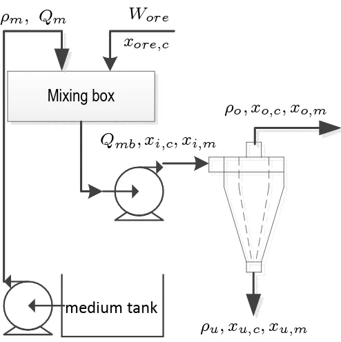
As depicted in the diagram shown in Fig. 1, the raw coal and medium (magnetite carried by water) are fed into a mixing box before entering the DMC. Output of the mixing box is then fed to the cyclone for separation [6].
The blended mixture enters tangentially at the inlet of the cyclone where a swirling fluid is formed. The heavy ash particles are driven to the wall of the cyclone by centrifugal force and exit the cyclone in the underflow. The lighter particles are caught into a upward vortex located at the center of the cyclone and exit the cyclone in the overflow. Because the carbon content is lighter and the impurities are heavier than the medium, the overflow of the cyclone after medium recycle is the clean coal obtained through DMC separation whilst the underflow is treated as rejects.
Detailed model for the DMC circuitry is given in the subsequent subsections.
A. Mixing box
Inflows of the mixing box are the ROM coal fed by conveyor belt and dense medium pumped from corrected medium tank in the plant. Assume that the fixed speed pumping of materials results in no rate of change of the volume inside the mixing box and that the medium and ore is well mixed in the box, the following equations can be derived according to mass balance.
xi,c=
xore,cWore
Wi
, (1)
xi,m =
Qmρm
Wi
, (2)
Mixing box
W
orex
ore;c½
m; Q
m½
o; x
o;c; x
o;m½
u; x
u;c; x
u;mQ
mb; x
i;c; x
i;m [image:2.612.314.561.49.297.2]medium tank
Fig. 1: DMC process diagram
where Wi = Wore+Qmρm, in which ρm and Qm are the density and volumetric flow rate of medium, Wore and Wi are the mass flow rate of ROM coal to the mixing box and in the slurry to the cyclone. Variables xore,c andxi,c represent the component percentages in the ROM coal and cyclone feed slurry, respectively. The subscript c denotes the set of {ash, sulphur, moisture, volatile}.xi,m is the percentage of medium in the cyclone feed slurry.
Note that only ash, sulfur, moisture, fixed carbon and volatile components in the coal are considered in the model due to the fact that the quality of coal is defined by these contents.
B. DMC
Based on mass balance analysis of the DMC, a dynamic model for DMC is developed by Meyer and Craig [17]. A brief introduction of this model is given in the following context. Assumptions made are:
• The volume of the mix in DMC is constant atVc m3.
• The volumes of the overflowVoand underflowVuslurries in the cyclone are split at a constant ratio α. That is,
Vo=1+ααVc andVu= 1+1αVc.
• The volumetric flow rates of the overflowQo and under-flowQu are also split at the constant ratioα.
• Only carbon, ash, sulfur, moisture and volatile com-ponents in the feed are considered. In other words,
xore,C+Pcxore,c= 1.
The relationships between the proportions of different com-ponents in the slurries that enter and exit the DMC are governed by the following equations [17].
˙
xo,c= 1
Voρo
Wixi,c−Qoρoxo,c−Quρuxu,c−Voxo,cρ˙o
−Vuxu,cρ˙u−Ku,cVuρu(ρc−ρm)(xi,c−xu,c),
˙
xu,c= 1
Vuρu
Wixi,c−Qoρoxo,c−Quρuxu,c−Voxo,cρ˙o
−Vuxu,cρ˙u−Ko,cVoρo(ρm−ρc)(xi,c−xo,c),
˙
xo,m=
1
Voρo
Wixi,m−Qoρoxo,m−Quρuxu,m
−Voxo,mρ˙o−Vuxu,mρ˙u −Ku,mVuρu(xi,m−xu,m)
,
˙
xu,m=
1
Vuρu
Wixi,m−Qoρoxo,m−Quρuxu,m
−Voxo,mρ˙o−Vuxu,mρ˙u −Ko,mVoρo(xi,m−xo,m)
,
˙
ρo= 1
Vo
Wi−Qoρo−Quρu−KuVu(ρu−ρm)xi,ash
,
˙
ρu= 1
Vu
Wi−Qoρo−Quρu−KoVo(ρo−ρm)xi,C,
(3) wherexo,c,xu,care4×1vectors that represent the percentages of components (ash, sulfur, moisture and volatile) in the overflow and underflow of the cyclone, respectively. ρo and
ρu are the densities of slurries exiting at the overflow and underflow of the cyclone. The volumetric parameterVcdenotes the volume of slurry inside the cyclone. Qo and Qu are the flow rates to the overflow and underflow of the cyclone. The
Ko,c,Ku,c,Ko,m andKu,m are DMC specific constants. The reasons why this model is chosen for controller design, as elaborated on in Section I, are that it has clear physical meanings and it is relatively easy to solve for a control system. And, it is verified to have an acceptable accuracy of capturing the dynamic behavior of the DMC by experimental data. The correlation between the model outputs and industrial measurements is higher than 0.72 with 95% confidence [17].
III. CONTROLLER DESIGN
The concept for controlling the dense medium circuit is depicted in Fig. 2. In coal preparation plants, the raw coal mined from different locations is sampled and analyzed [18]. This analysis provides the coal washing plant with the prior information about the percentages of different components in the raw coal. Measurement of the same information of fines after DMC separation is not practiced for control purpose because the accurate measurement and analysis take a long time and is very costly.
Under such a circumstance, the measured component per-centages in the coal feed xore,c and the coal feed rate Wore are used as feed-forward signals for the controller as shown in Fig. 2. The control law is determined by using this feed-forward information and the cyclone circuit process mod-el [19], [20]. In other words, the control is to ensure the quality of the fine coal product by manipulating the relative density of dense medium according to feed forward measurement.
As for performance indicators of the control system de-signed, the following objectives are used:
1) Keep the percentage of the fixed carbon content in the fines stable.
2) Minimize energy consumption of the circuit while ensur-ing carbon content in the fines within prescribed interval.
For most cases, the goal of DMC process control is to minimize the operating cost while maintaining the quality of the fines to an acceptable level during the operation.
For this purpose, the following objective function is em-ployed.
J =
Z T
0
α(xo,C(t)−xr(t))2+β
Qmρmgh 1000ηpηm
dt, (4)
wherexo,C(t) andxr(t)are the actual and reference carbon percentage in the fines at time t, [0, T] is the optimization interval.αandβ are tuning weights. The second term in this function represents the energy consumption of the pump that supplies dense medium to the DMC,Qmis the volumetric flow rate of the medium,his the differential head of the pump,gis gravity acceleration.ηmandηpare motor and pump efficiency coefficients, respectively. It can be seen that minimizing the medium density is a direct way to bring down the operating cost because the medium is pumped to the mixing box as shown in Fig. 1. Minimizing medium density can lead to energy cost savings of the pumps as the power of pump is proportional to the density of the pumping fluid.
The physical and operational constraints on the system dynamics and control variables are given below:
0≤xo,c(t)≤1, (5)
0≤xu,c(t)≤1, (6)
xo,C(t) +
X
c
xo,c(t) = 1, (7)
xu,C(t) +
X
c
xu,c(t) = 1, (8)
|ρm(t)−ρm(t−1)| ≤∆ρm, (9)
ρlm≤ρm(t)≤ρum. (10)
The constraint (5) and (6) indicate that percentages of each content in the cyclone overflow and underflow must be from zero percent to a hundred percent. Constraints (7) and (8) ensure that summation over the percentages of all the contents in the cyclone overflow and underflow must be equal to one hundred percent. Inequalities (9) and (10) restrict the rate of change and physical boundary of the medium density to be less than ∆ρmand within [ρlm, ρum], respectively.
The first term in the objective function (4) presents an soft constraint on the proportion of carbon content in fines to track a set value. To ensure the coal quality is within acceptable level, a hard constraint on the variation of carbon content in the fine product is also included in (11).
xlo,C ≤xo,C(t)≤xuo,C. (11)
Controller
Wore xore;c
½m
DMC process
w
Measurement
Update using the most recent measurements
New measurement available?
Y Solve the optimisation problem to obtain
Apply to the plant N ½m ½m
[image:4.612.50.304.55.341.2]½m
Fig. 2: Control diagram
0 500 1000 1500
4 6 8 10
Coal feed rate (kg/s)
Time (s)
Fig. 3: Coal feed rate
As given in Section II-B, the dynamic model of the DMC is nonlinear. To achieve the goal of optimal control, the nonlinear optimization problem, minimize (4) subject to the cyclone process dynamics (1)–(3) and operational constraints (5)–(11), is solved by the controller to determine the optimal medium density.
As the measurement on component percentages of ROM are done on sampling basis, the control action optimised by the controller is implemented during the period when no new measurement is available. That is to say, the control action is implemented according to current measurement and the action is changed when this feed forward measurement is updated. Fig. 2 demonstrates the work principles and implementation implications of the controller designed.
IV. SIMULATION
Based on plant measurements from a South African coal mine, simulations are carried out to verify and evaluate the feasibility and effectiveness of the control strategy proposed. The optimization problem is solved using the standard sequen-tial quadratic programming method and simulations are carried out on Matlab platform. The DMC process related parameters and result analysis are given in the following.
A. Parameters
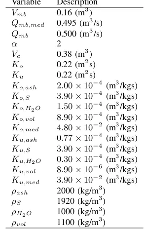
[image:4.612.362.509.71.304.2]The model parameters used are listed in Table I [17]. The coal feed rate over time is shown in Fig. 3. The limits for the control variable ρm are, ρlm = 1200 (kg/m3), ρum = 1620(kg/m3) and∆ρm= 0.3571(kg/m3s), respectively. The
TABLE I: Cyclone separation circuit model parameters Variable Description
Vmb 0.16 (m3) Qmb,med 0.495 (m3/s) Qmb 0.500 (m3/s)
α 2
Vc 0.38 (m3) Ko 0.22 (m2s) Ku 0.22 (m2s)
Ko,ash 2.00×10⁻⁴ (m3/kgs) Ko,S 3.90×10⁻⁴ (m3/kgs) Ko,H2O 1.50×10
−4
(m3/kgs)
Ko,vol 8.90×10⁻⁴ (m3/kgs) Ko,med 4.80×10⁻² (m3/kgs) Ku,ash 0.77×10⁻⁴ (m3/kgs) Ku,S 3.90×10⁻⁴ (m3/kgs) Ku,H2O 0.30×10⁻⁴ (m3/kgs) Ku,vol 8.90×10⁻⁶ (m3/kgs) Ku,med 3.90×10⁻² (m3/kgs) ρash 2000 (kg/m3) ρS 1920 (kg/m3) ρH2O 1000 (kg/m
3
)
ρvol 1100 (kg/m3)
coefficients of the pumping systemηm andηp are set to 0.8 and 0.6.
At the beginning, the ash, sulfur, moisture, and volatile percentages in the coal feed are 17.6%, 2.5%, 1.59%, and 12.6%, respectively. At timet=600 s, new measurements of these percentages are available as 16.2%, 2.8%, 1.59%, and 13.0%. At timet=1200 s, these percentages are changed back to 17.6%, 2.5%, 1.59%, and 12.6%. As for the coal feed rate, the measured values shown in Fig. 3 is used in all simulations. In simulations, the nonlinear DMC dynamics is solved by fourth-order Runge-Kutta method. According to industrial practice and information obtained from [17], sampling period of the controller is set to 14 s. The optimisation problem is solved by the fmincon function of the Matlab optimisation toolbox.
B. Results analysis
The simulation results are given in this section along with some analysis.
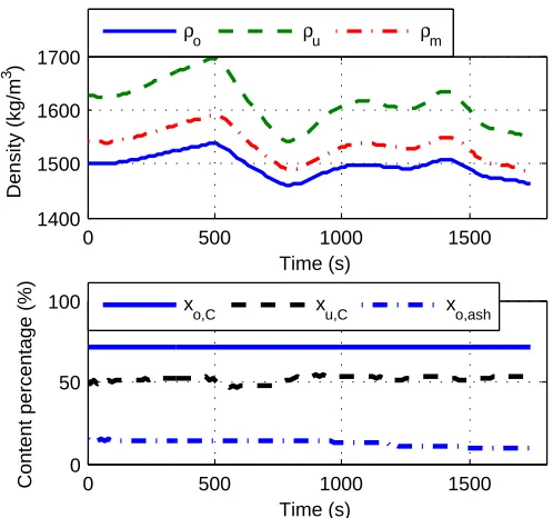
1) Results with α= 5000, β = 0: In this simulation, the desired carbon percentage in the fine coal is set to 72%. Allowing a ±1% deviation from this set target, xl
o,C and
xu
o,C are set to 71% and 73%, respectively. The controller is tuned such that only tracking of carbon percentage in the fines is considered (β set to 0). The results are shown in Fig. 4, in which the first subplot shows the manipulated medium densityρmand densities of the cyclone overflow and underflow slurries. Percentages of fixed carbon and ash content in the fines and rejects are sketched in the second subplot.
0 500 1000 1500 1400
1600 1800
Time (s)
Density (kg/m
3)
ρo ρu ρm
0 500 1000 1500
0 50 100
Time (s)
Content percentage (%)
x
[image:5.612.313.562.55.288.2]o,C xu,C xo,ash
Fig. 4: Results of with α= 5000andβ = 0
TABLE II: Results with various weights Weights |e| E(kWh) Creject (ton)
α= 5000,β= 0 0.00% 465.49 2.19
α= 5000,β= 0.08 0.16% 452.73 2.41
α= 5000,β= 0.1 0.21% 449.03 2.48
α= 5000,β= 0.12 0.26% 445.11 2.55
simulated mean value of the carbon percentage in the overflow of cyclone is 72.00% with no tracking error. This verifies the effectiveness of the control strategy presented for the DMC process. The energy consumption resulted from this control is E =RT
0
Qmρmgh
1000ηpηmdt= 465.49kWh during the simulation
period.
To investigate separation efficiency, carbon content trapped in the DMC rejects are calculated. In this case study, the ROM coal feed to the separation process during the simulation period is 13.72 ton, in which carbon content is 9.02 ton. After the DMC process, carbon trapped in the rejects is 2.19 ton. 75.72% carbon in the feed coal is separated to the fine product.
2) Results with α = 5000, β = 0.08: Fig. 5 gives an illustration of the results when both carbon content tracking and energy consumption of the DMC process are accounted for. Results of this simulation show that energy consumption of the DMC process can be reduced with minimal sacrifice in DMC separation efficiency. The mean proportion of carbon content in the fines is 71.88% with a relative tracking error |e| = xo,C−xr
xr = 0.16%. Energy consumption of the DMC
process in this case is 452.73 kWh.
In comparison with the case whenβ= 0, the carbon content tracking error increased from 0 to 0.16% while the energy consumption decreased by 2.74%.
In order to study the effects of tuning weights on the controller designed, four scenarios with different weights are shown in Table II where |e|, E and Creject represent the relative absolute tracking error from the set carbon percentage, energy consumption and carbon content reported to the rejects, respectively. In the table, it can be seen clearly that energy
0 500 1000 1500
1400 1500 1600 1700
Time (s)
Density (kg/m
3 )
ρo ρu ρm
0 500 1000 1500
0 50 100
Time (s)
Content percentage (%)
x
[image:5.612.60.294.56.273.2]o,C xu,C xo,ash
Fig. 5: Results withα= 5000andβ= 0.08
consumption of the DMC process is decreasing when β
increases. By contrast, the absolute mean tracking error of the carbon content elevates during this process. In specific, when
β increases from 0 to 0.1, the energy consumption of DMC process falls down by 3.54% and|e| raised from 0 to 0.21%. On one hand, the coal washing plant studied is operating 16 hours per day with 15 DMC modules, the 3.54% energy reduction when β increases from 0 to 0.1 translates to a daily energy saving of 7.91 MWh under the same operating condition. This amounts to an annual energy saving of 2.89 GWh. According to the local electricity tariff, annual energy cost savings resulted from this reduction is 3.57 million South African Rand (approximately equivalent to 0.43 million US Dollar). On the other hand, the deviation of carbon percentage in the fines increased by a minimal percentage and the carbon trapped in DMC rejects increased from 2.19 ton to 2.48 ton, increased by 13.24%.
In addition, comparing Fig. 4 and 5, it is clear that when largerβis used, the medium density is manipulated to be lower to reduce the pumping energy required to move them. This also leads to changes in the densities of the DMC overflow and underflow slurries, which ultimately affects the carbon percentages in the fines and rejects.
The effects of the tuning weights suggest that the plant operators should choose the weights according to their pref-erence on the tracking of carbon content in fines and the corresponding energy cost. Therefore, a trade-off must be made.
C. Influence of measurement uncertainties
0 500 1000 1500 1500
1600 1700
Time (s)
Density (kg/m
3 )
0 500 1000 1500 14
16 18 20
ash in feed coal (%)
ρo ρu ρm
0 500 1000 1500
0 50 100
Time (s)
Content percentage (%)
x
o,C xu,C xo,ash
Fig. 6: Influence of feed ash content
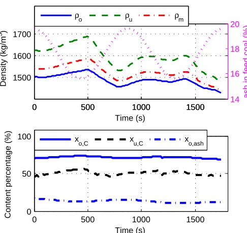
the feed forward controller designed against the measurement uncertainties, following simulation is conducted.
A sinusoidal changing disturbance with magnitude of 2,
w= 2 sint, is added on top of the ash content in the ROM coal as shown in Fig. 2. While the density of medium optimised according to available measurements still implemented, the results are shown in Fig. 6 (tuning weights are set toα= 5000 andβ= 0.1). Carbon content resulted from this simulation is 71.46%, incurring a relative tracking error of 0.75%. Energy consumed therein is 449.03 kWh and carbon content reported to rejects is 2.41 ton.
In Fig. 6 the time-varying ash content is shown in the first subplot as dotted line. The carbon tracking results verify that the controller is effective under measurement uncertainties.
In comparison to the situation when no measurement un-certainties considered (the results given in the fourth row of Table II), the carbon content tracking error increased from 0.21% to 0.75%, energy consumption remained the same and carbon trapped in rejects decreased from 2.48 to 2.41 ton.
V. CONCLUSION
A model based control strategy for coal washing dense medium cyclone (DMC) circuits is proposed. The objective of the control is to guarantee the fine coal quality from DMC output while minimising energy consumed by the DMC separation process. The controller is designed basing on a DMC model derived from mass flow balance. Simulations are carried out to verify the feasibility and effectiveness of the control approach proposed. The results demonstrate that controlling the density of the medium used for enhancing the separation efficiency of the DMC is able to improve the desired efficiency of the DMC circuit in terms of improving fine coal quality and reducing energy cost. According to numerical analysis of the results obtained, it is possible to maintain the required coal quality and reducing the annual
energy cost of 3.57 million South African Rand (0.43 million USD equivalent) for a plan with 15 DMC modules operating for 16 hours per day. It is also affirmed by the simulation that the proposed controller is able to work under measurement uncertainties.
ACKNOWLEDGMENT
The authors would like to thank Mr. E.J. Meyer for supply-ing the measurement data and model parameters of the coal beneficiation plant.
REFERENCES
[1] J. Kohler, J. Sottile, and D. S. Placha, “Process control of heavy-media systems for coal-preparation plants,” IEEE Transactions on Industry Applications, vol. IA-23, no. 2, pp. 382–388, 1987.
[2] G. H. Luttrell, J. N. Kohmuench, and R.-H. Yoon, “An evaluation of coal preparation technologies for controlling trace element emissions,” Fuel Processing Technology, vol. 65C66, no. 0, pp. 407 – 422, 2000. [3] V. Gupta and M. Mohanty, “Coal preparation plant optimization: A
critical review of the existing methods,”International Journal of Mineral Processing, vol. 79, no. 1, pp. 9 – 17, 2006.
[4] D. G. Osborne, “Fine coal cleaning by gravity methods: A review of current practice,”Coal Preparation, vol. 2, no. 4, pp. 207–241, 1986. [5] B. A. Firth, “Dense medium cyclone control–a reconsideration,”
Inter-national Journal of Coal Preparation and Utilization, vol. 29, no. 3, pp. 112–129, 2009.
[6] K. J. Kindig, “Coal cleaning process,” Genesis Research Corporation, US patent EP0608325 A1, 1994.
[7] M. Narasimha, M. S. Brennan, and P. N. Holtham, “A review of flow modeling for dense medium cyclones,”Coal Preparation, vol. 26, no. 2, pp. 55–89, 2006.
[8] T. Napier-Munn, “Modelling and simulating dense medium separation processes–a progress report,”Minerals Engineering, vol. 4, no. 3C4, pp. 329 – 346, 1991.
[9] M. Narasimha, M. Brennan, P. Holtham, and T. Napier-Munn, “A comprehensive CFD model of dense medium cyclone performance,” Minerals Engineering, vol. 20, no. 4, pp. 414 – 426, 2007.
[10] K. Chu, B. Wang, A. Yu, A. Vince, G. Barnett, and P. Barnett, “CFD– DEM study of the effect of particle density distribution on the multiphase flow and performance of dense medium cyclone,”Minerals Engineering, vol. 22, no. 11, pp. 893 – 909, 2009.
[11] K. Chu, B. Wang, A. Yu, and A. Vince, “CFD–DEM modelling of multiphase flow in dense medium cyclones,”Powder Technology, vol. 193, no. 3, pp. 235 – 247, 2009.
[12] ——, “Particle scale modelling of the multiphase flow in a dense medium cyclone: Effect of vortex finder outlet pressure,” Minerals Engineering, vol. 31, no. 0, pp. 46 – 58, 2012.
[13] L. Shen, Y. Hu, J. Chen, P. Zhang, and H. Dai, “Numerical simulation of the flow field in a dense-media cyclone,”Mining Science and Technology (China), vol. 19, no. 2, pp. 225 – 229, 2009.
[14] Y. Tsuji, T. Tanaka, and T. Ishida, “Lagrangian numerical simulation of plug flow of cohesionless particles in a horizontal pipe,” Powder Technology, vol. 71, no. 3, pp. 239 – 250, 1992.
[15] H. H. Shalaby, “On the potential of large eddy simulation to simulate cyclone separators,” Ph.D. dissertation, Chemnitz University of Tech-nology, Jan. 2007.
[16] J. Chen, K. Chu, R. Zou, A. Yu, and A. Vince, “Prediction of the performance of dense medium cyclones in coal preparation,”Minerals Engineering, vol. 31, no. 0, pp. 59 – 70, 2012.
[17] E. Meyer and I. Craig, “The development of dynamic models for a dense medium separation circuit in coal beneficiation,”Minerals Engineering, vol. 23, no. 10, pp. 791 – 805, 2010.
[18] A. Majumder and J. Barnwal, “Processing of coal fines in a water-only cyclone,”Fuel, vol. 90, pp. 834–837, 2011.
[19] T. Rabbani, F. Di Meglio, X. Litrico, and A. Bayen, “Feed-forward con-trol of open channel flow using differential flatness,”IEEE Transactions on Control Systems Technology, vol. 18, no. 1, pp. 213–221, 2010. [20] C. Schmuck, F. Woittennek, A. Gensior, and J. Rudolph, “Feed-forward
[image:6.612.53.296.52.281.2]