University of Southern Queensland
Faculty of Engineering and Surveying
Design and Development of a Conveyor System
for Semiconductor Industry
A dissertation submitted by
LIM DOOU GIE
In fulfilment of the requirements of
Courses ENG4111 and 4112 Research Project
towards the degree of
Bachelor of Engineering (MECHANICAL)
Abstract
Conveyor system is an essential part in a Semiconductor Industry. It is used to transfer
leadframes from one work station to another. As leadframe is a very delicate item and
care must be taken not to damage them as any scratch marks or dents found on it will lead
to it being scraped. Therefore, the design of the conveyor system is important. A good
conveyor system will help to save up in the production process, time and most
importantly cost.
Nowadays, companies with high end products have suddenly swamp into Singapore. This
is due to it’s attractive location, extensive telecommunications connectivity, superior
logistics and supply chain infrastructure. Companies like Matsushita Electric and
Chartered Semiconductor has invested hundreds of million dollar into it. These show that
the semiconductor market is in the midst of a strong growth in equipment and materials,
and all indications are that this trend will continue for a long time. Therefore a good
process line is required for the manufacturing of the products in order to keep pace with
the ever increasing demand. This is when a good conveyor system comes in handy.
The main objectives of this research project are to:
• Design and develop a custom made conveyor system to help in transferring the
leadframe from the press machine to the stacker, whereby the leadframe will be
nicely stack up after being cut, without damage.
• Separate the four strands of leadframes that is been cut out from a coil by the press
machine, to aid in the stacking process.
University of Southern Queensland
Faculty of Engineering and Surveying
ENG4111 & ENG4112 Research Project
Limitations of Use
The Council of the University of Southern Queensland, its Faculty of Engineering and Surveying, and the staff of the University of Southern Queensland, do not accept any responsibility for the truth, accuracy or completeness of material contained within or associated with this dissertation.
Persons using all or any part of this material do so at their own risk, and not at the risk of the Council of the University of Southern Queensland, its Faculty of Engineering and Surveying or the staff of the University of Southern Queensland. This dissertation reports an educational exercise and has no purpose or validity beyond this exercise. The sole purpose of the course pair entitled "Research Project" is to contribute to the overall education within the student’s chosen degree programme. This document, the associated hardware, software, drawings, and other material set out in the associated appendices should not be used for any other purpose: if they are so used, it is entirely at the risk of the user.
Prof G Baker
Dean
Certification
I certify that the ideas, designs and experimental work, results, analyses and conclusions set out in this dissertation are entirely my own effort, except where otherwise indicated and acknowledged.
I further certify that the work is original and has not been previously submitted for assessment in any other course or institution, except where specifically stated.
LIM DOOU GIE
Student Number : 0031135732
Acknowledgements
I would like to express my sincere thanks to both my supervisors, Dr. Harry Ku and Dr. Yen Wenyi, for their endless help and guidance in making this project possible and successful.
In addition, I would also like to thank my subordinates and staff of SMMAP for their understanding and assistance in helping me towards completing the project.
Contents
i iv x 1 1 2 3 5 5 8 9 9 10 11 12 13 13 14 14 Abstract AcknowledgementsList of Figures
Chapter 1 Introduction
1.1 Importance of Conveyor System 1.2 Definition of a Conveyor System 1.3 Types of Conveyor System
Chapter 2 Background
2.1 Overview of Semiconductor Industry 2.2 Definition of Leadframe
2.3 Most Common Basic Elements 2.3.1 Silicon
2.3.2 Aluminium 2.3.3 Gold 2.3.4 Silver 2.3.5 Copper
16 17 17 18 18 18 19 22 22 27 31 31 31 32 32 32 32 33 33 34 34 34 34 34 37 39 39 40
Chapter 3 Objectives of the Project
Chapter 4 Methodology
4.1 Gathering of Information 4.1.1 Problems Encountered 4.1.2 Project Specifications 4.1.3 Allocating of Task 4.2 Development of Ideas 4.3 Finalisation of Design
4.3.1 Working Principles 4.4 General Approach
Chapter 5 Selection of Components
5.1 Conveyor Belt
5.1.1 Components of Conveyor Belt 5.1.1.1 Carcass
5.1.1.2 Breaker 5.1.1.3 Top Cover 5.1.1.4 Bottom Cover 5.1.2 Belt Material
5.1.2.1 Nylon 5.1.2.2 Polyester 5.1.2.3 Polyurethane 5.1.3 Belt Splice Techniques
5.1.3.1 Vulcanized Splice 5.1.3.1 Mechanical Splice 5.1.4 Belt Training
5.2 Bearing
41 41 41 41 43 43 43 44 44 44 45 46 46 49 53 54 55 55 55 55 56 56 56 58 58 58 5.2.2.1 Ball Bearing
5.2.2.2 Roller Bearing
5.2.2.3 Self-Aligning Bearing 5.2.2.4 S-Bearing Unit
5.3 Motor and Gearhead 5.3.1 Types of Motor
5.3.1.1 Basic Motor 5.3.1.2 Brake Motor
5.3.1.3 Speed Control Motor 5.3.1.4 Linear Head Motor 5.3.2 Selection Procedure
5.3.3 Sizing of Motor
5.3.3.1 Main Conveyor 5.3.3.2 Sub Conveyor
5.4 Belt and Pulley
5.4.1 Advantages and Disadvantages 5.4.2 Problems with Belt
5.4.3 Types of Belt 5.4.3.1 Flat Belt 5.4.3.2 Round Belt 5.4.3.3 V-Belt 5.4.3.4 Timing Belt 5.4.4Speed Ratio
5.5 Conveyor Structure 5.5.1 Materials
60 60 60 61 61 61 62 62 63 63 64 64 65 66 68 69 71 72 73 74 74 75 78 80 81 82
Chapter 6 Safety Aspects
6.1 Areas to Take Note 6.1.1 Electricity 6.1.2 Belt and Pulley 6.1.3 Motor
6.1.4 Structure 6.2 General Guidelines
6.2.1 Safety Acts for Assembly and Installation 6.2.2 Safety Precaution for Operation Procedures
6.2.2.1 Before Operation 6.2.2.2 During Operation 6.2.2.3 After Operation 6.2.3 Emergency Act
Chapter 7 Project Performance
7.1 Test Result 7.2 Comparison Test 7.3 Aspect of Sustainability 7.4 Ethical Responsibility
Chapter 8 Conclusion
8.1 Achievement of Project Objectives 8.2 Further Work
References
Appendix A Project Specification
Appendix B Project Information
83
84 85 91 92 93 104 106 107
Appendix C Assembly Drawings
C.1 Main Conveyor C.2 Sub Conveyor C.3 Pictures
Appendix D Data Sheets
D.1 General D.2 Conveyor Belt D.3 Bearing
D.4 Motor and Gearhead D.5 Timing Belt
List of Figures
Symbol Description ___________________________________________________________________________________________________
Si Silicon Al Aluminium Au Gold Ag Silver Cu Copper
Chapter 1
Introduction
Nowadays modern manufacturing methods dictate the use of material handling systems. Material handling is an integral part of many continuous processes. There are two basic methods used for moving materials: nonpowered material handling systems and powered material handling systems.
Nonpowered systems use gravity as the motive force and include devices such as chutes and slides, which are the simplest and least expensive methods available. However they require the starting point to be at a certain minimum elevation higher than the end point. In most material handling situations, this is rarely the case.
For moving material horizontally, vertically, over extended distances, or in a controlled fashion, powered material handling systems are required.
1.1
Importance of a Conveyor System
important of all, semiconductor industries. Some conveyors can provide minor processing functions such as heating and cooling, but this is supplementary to the primary materials handling function.
Conveyor system is an essential part in a Semiconductor Industry. It is needed during the work process to transfer leadframe from one work station to another. Leadframe is a very delicate item and care must be taken not to damage them as any scratch marks or dents found on it will lead to it being scraped. Therefore, the design of the conveyor system is important. The materials, speed and belt used play an important part in the designing process. A good conveyor system will help to save up in the production process, time and most importantly cost.
1.2
Definition of Conveyor System
The following gives the definition of a conveyor:
A conveyor includes all fixed and portable equipment capable of moving material in a continuous or intermittent fashion, between two or more points, along a fixed path. While the material may be delivered intermittently, the drive operates continuously. The movement of material can be horizontal, vertical, inclined, or any combination of the three.
1.3 Types of Conveyor System
There are so many kinds of conveyor in the market. Which one of them is most suitable to be used in this project has to depend on its functionality. Let us look at some of the common types of conveyor.
1.3.1 Powered Rollers
Powered rollers conveyors,straight or curved, are extensively used for heavy and arduous applications such as rolling mills and foundries. They are also an ideal medium in package handling for systems where it is necessary to stop, meter, or manipulate articles without stopping the conveyor. It is also an economical way of moving heavy loads in limited space.
1.3.2 Chain
Chain conveyors have been designed to cover many varied applications in industry and employ several distinct patterns including twin chain, multiple chain, in-floor, on-floor and heavy duty overhead. They are particularly useful where high temperatures are involved, and special designs with expansion joints and automatic spray lubrication are available.
1.3.3 Belt
1.3.4 Slat
Chapter 2
Background
Nowadays, companies with high end products have suddenly swamp into Singapore. This is due to its attractive location, extensive telecommunications connectivity, superior logistics and supply chain infrastructure. These show that there is a high demand for the semiconductor products.
2.1 Overview of Semiconductor Industry
According to Stanley T. Myers, President and CEO, SEMI, these companys continue to see Singapore as an attractive location because of its business-friendly environment, respect for intellectual property, extensive telecommunications connectivity, skilled workforce, and superior logistics and supply chain infrastructure.
STMICROELECTRONICS NV, Europe’s largest semiconductor maker, will invest another $2 billion over the next two years in Singapore, a move that will bring its total investment here to $6.7 billion by the end of 2006.
STMicroelectronics, which accounted for about 19 per cent of Singapore’s semiconductor production last year, will invest the funds to increase its capacity. Last year, its manufacturing output in Singapore was $3.9 billion, compared with overall industry production in the nation of $21 billion, according to Trade Minister Lim Hng Kiang.
STMicroelectronics, based in Geneva, said that it made chips in Singapore for products such as cell phones equipped with digital cameras. According to a company press release, STMicroelectronics is the only semiconductor company in Singapore with a fully-integrated manufacturing value-chain employing about 7400 staff.
Several other device makers have increased their resources in Singapore recently. They include Matsushita Electric Industrial, which selected Singapore as the site for a new S$150 million assembly and test facility for charged coupled device (CCD) image sensors. Last year Infineon Technologies announced plans to increase its R&D headcount here to more than 350 and to make Singapore its global logic IC testing hub. In February, Xilinx said it would establish its Asia Pacific headquarters in Singapore, employing about 200 people. Then a month later foundry Chartered Semiconductor Manufacturing revealed plans to start outfitting its 300mm fab shell.
For SMMAP, the sponsor of this project, it has been constantly upgrading its working processes and machine performances to cope with the ever increasing high demands and standards of semiconductor products.
tapping into the excellent infrastructure for the manufacture of subsystems and components.
All these companies have invested millions of dollars for the new technologies and facilities. These show that the semiconductor market is in the midst of a strong growth in equipment and materials, and all indications are that this trend will continue for a long time.
[image:18.612.131.503.417.625.2]According to a source from SICAS, in a market where the 2004 August year-to-date world growth rate is 35 %, Asia-Pacific is growing at a rate of 50% and the three other regions are growing by roughly half of that. The Asia-Pacific share of the world market has grown to 42 %. Semiconductors are made to be assembled into end electronic equipment, which is what Asia-Pacific has grown increasingly adept at doing well and at the right price. Figure 2.1 shows the regional market trends for Semiconductors.
These show that there is a high demand for the semiconductor products. Therefore a good process line is required for the manufacturing of the products in order to keep pace with the ever increasing demand. This is when a good conveyor system comes in handy.
2.2 Definition of Leadframe
Other than common items like IC Chips, transistor, LED & wafers, leadframes are also one of the products from semiconductor industry. Over SMMAP, surface plating of lead frame is been processed and the end products are mainly in both coil form or strip form. It is the processing of leadframe that SMMAP is dealing with. Figure 2.2 shows the different types of leadframes.
[image:19.612.187.461.370.461.2]
Figure 2.2 Different Types of Leadframes
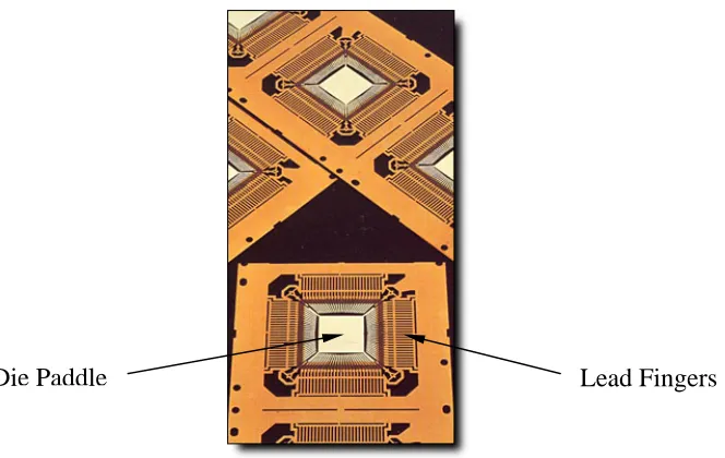
Figure 2.3 Features of Leadframe
Lead Fingers Die Paddle
Plastic package leadframes are made of alloys that meet the following critical properties: good adherence to the molding compound, a coefficient of thermal expansion as close as possible to those of the die and the molding compound, high strength, good formability, and high electrical and thermal conductivities. Alloy 42 is an example of such an alloy. However most of the leadframes are made of Cu.
2.3 Most Common Basic Elements
2.3.1 Silicon
Si is the most commonly used basic building block of integrated circuits. Si is a semiconductor, which means that its electrical behavior is between that of a conductor and an insulator at room temperature.
layers are used to isolate conductive lines and the individual components in the circuit from each other.
Si is also widely used in semiconductor packaging, being the main ingredient of plastic encapsulants for integrated circuits. It is also used in die overcoats.
Property Value Property Value
Atomic Number 14 Melting Point 1410 deg C Atomic Group 14 or IVA Boiling Temp 2355 deg C Atomic Weight 28.086 Specific Gravity 2.33
Table 2.1 Silicon’s Basic Properties
2.3.2 Aluminium
Al is a lightweight metal with silvery appearance. It is the most abundant metallic element on earth. It is used in many aspects of semiconductor manufacturing. On the integrated circuit, Al metal lines are commonly used as the main conductor between components, mainly because of its low resistivity (2.7 mohm-cm). As a thin film, it also has good adherence to silicon dioxide.
Al is also the metallization used for the bonding and probing pads on the die. When used for IC metallization, Al is usually very lightly doped with other elements such as Si and/or Cu to improve its characteristics and reliability.
In semiconductor assembly, ceramic packages are composed mainly of alumina. Al is also used for wirebonding integrated circuits in ceramic packages.
Property Value Property Value
Atomic Number 13 Melting Point 660 deg C Atomic Group 13 or IIIA Boiling Temp 2467 deg C Atomic Weight 26.9815 Specific Gravity 2.7
Table 2.2 Aluminium’s Basic Properties
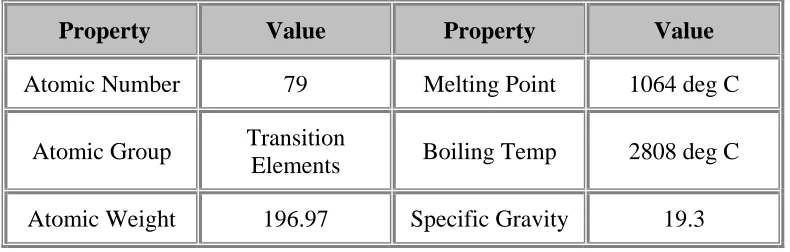
2.3.3 Gold
Au is a soft metallic element that is bright yellowish in color. A good conductor of heat and electricity, it is also the most malleable and ductile of all metals.
Au is used in many aspects of semiconductor manufacturing, particularly in the assembly or packaging processes. Its most widespread use is in wirebonding. Because of its excellent conductivity and ductility, it is extensively used in making wires for the connection of the integrated circuit to the leads of the package. Aside from manufacturability, the ductility of Au wires offers one more advantage when used in plastic-encapsulated devices, i.e., it makes the wires resistant to wire breaking during the encapsulation process.
Au is also used as die attach material for the eutectic die attach process, which is commonly used in old hermetic assembly processes. It is also used to cover the die cavity and bonding posts of ceramic packages to protect these from chemical degradation.
Property Value Property Value
Atomic Number 79 Melting Point 1064 deg C
Atomic Group Transition
[image:23.612.123.518.63.189.2]Elements Boiling Temp 2808 deg C Atomic Weight 196.97 Specific Gravity 19.3
Table 2.3 Gold’s Basic Properties
2.3.4 Silver
Ag is a shiny metallic element used for ornamental and coinage purposes since the ancient times. It is next only to gold in terms of malleability and ductility, and is also a good conductor of heat and electricity. In fact, silver is the best conductor of electricity, better even than copper and gold.
Ag, like Au, is used in many facets of semiconductor manufacturing, again more particularly in the assembly or packaging processes. Most epoxy die attach materials contain silver fillers for increased thermal and electrical conductivity. Ag is also used to cover the surfaces of the die pad and bonding fingers of the leadframes of plastic packages to prevent chemical degradation of these areas, which may lead to die attach and bonding problems.
Property Value Property Value
Atomic Number 47 Melting Point 962 deg C
Atomic Group Transition
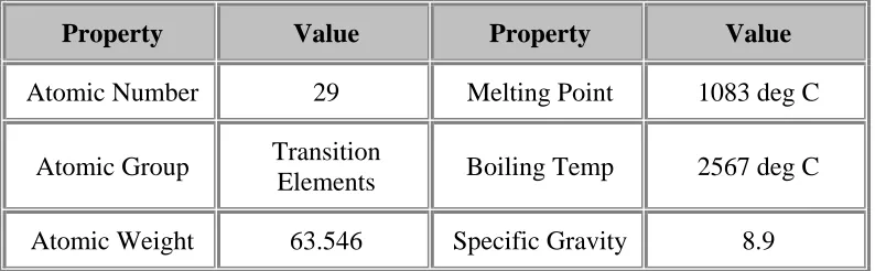
[image:23.612.122.518.560.683.2]2.3.5 Copper
Cu is one of the most widely used metals in the history of mankind, mainly because of its many desirable properties. It is the second best conductor of electricity, next only to silver but better even than gold. It is also very malleable and ductile, and is also a good conductor of heat.
Cu is also widely used in semiconductor assembly. For instance, most leadframes for plastic packages are composed of copper. The leadframe is the skeletal support of a plastic package.
Cu, being an excellent conductor, would have been a very good candidate for use in metal lines in an integrated circuit, but difficulties in the manufacturing of IC's using Cu for metallization resulted in Al being the metal of choice for this purpose. Recent technological advancements though have already allowed the use of Cu as metal lines in semiconductor devices.
Property Value Property Value
Atomic Number 29 Melting Point 1083 deg C
Atomic Group Transition
[image:24.612.122.519.413.536.2]Elements Boiling Temp 2567 deg C Atomic Weight 63.546 Specific Gravity 8.9
Table 2.5 Copper’s Basic Properties
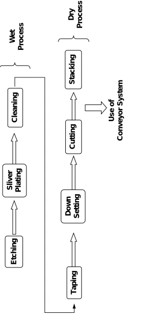
2.4 Types of Processes
2.4.1 The Wet Process
In wet process, chemical solutions and water is used throughout the etching, plating and cleaning processes. Etching consists of selectively covering the sheet metal with photoresist in accordance with the pattern of the leadframe. The sheet metal is then exposed to chemical etchants that remove areas not covered by photoresist.
Silver plating is done on the bonding fingers and die-pad to improve wirebond and die attach quality. After that the whole strip is cleaned with distilled water to remove all the chemical solution before passing through a blower to dry up. The end product is then coil up again for the subsequent dry process.
2.4.2 The Dry Process
For dry process, no chemical or water is needed. During this stage, taping, down-setting and cutting is done.
Taping consists of putting a lead lock tape over the leads to prevent lead deformation, while downsetting consists of pushing the die paddle down relative to the bonding fingers in compliance with standard industry requirements.
In Cutting, the required length of the leadframe is cut out from the long strip of coil using a stamping machine. From here the leadframe is then sent to a machine called ‘Stacker’ to stack up the strips of leadframe. For this to be able to carry out, a conveyor system is necessary.
Sliver
Plating
Cleaning
Etching
Taping
Down
Setting
Cutting
Stacking
Use of
[image:26.612.184.476.65.699.2]Conveyor System
Figure 2.4 W
o
rk Process
of L
eadf
ram
es
Wet
Process
Dry
Chapter 3
Objectives of the Project
The objectives of this project is to develop a custom made conveyor system to help in transferring the leadframe from the press machine to the stacker, whereby the leadframe will be nicely stacked up after being cut, without damage. It must link up well with the press and stacker machine. In addition, it must be able to separate the many strand of leadframes cut out by the press machine at a time to aid in the stacking process. This ultimate system will help to save a lot in the production process, time and cost.
Chapter 4
Methodology
Before starting on the project, a detail specification had to be prepared for the conveyor to be based on. So a meeting with the people involve is a must so that the project group can have a better understanding of the require system. Typically, the specification will contain information regarding the size, capacity, and layout of the conveyor system.
The peoples involve in the meeting include the customers, project managers, engineers, supervisors, technicians and even the operators from the related field.
4.1 Gathering of Information
4.1.1 Problems Encountered
Currently the present conveyor systems have a lot of problems. After checking, it was found that the systems cannot meet the new requirement and some of problems are due to wear. Below are the problems faced by the operators during production:
- Speed of the present conveyor is too slow and it cannot catch up with the outputs from the new press machine.
- It can only handle one piece of leadframe at a time.
- Conveyor belt gets loose easily. It does not have a proper tension. - Black residue can be found around the bearings. It may due to wear. - Conveyor belt tends to run and it is not in the center during operation.
4.1.2 Project Specifications
Specification of system is base on the customer requirement, so the system built must either meet the specification or exceeds the expectation. Below are some of the important areas:
- The different sizes of the leadframe which is to be run in the production. - The speed range that the press machine has to be operated during production. - The specific type of material that must be used for the system.
- The overall size of the whole system. - The power rating for the electrical supply. - The project schedule to let people.
4.1.3 Allocating of Task
Task allocating is important as it gives the people involved a clearer view of their responsibilities and their job scope. The type of task include:
- The new concept design for the new stacker machine with the conveyor system.
- Mechanical installation for the whole unit. - Electrical wiring and test run of the unit.
After the meeting with the persons involved, all the specifications and information is consolidated. Any changes to all these from the customer have to be discussed again and updated to everyone involved quickly. That is often why there are a few meetings to a project. The specifications and schedule for the project is tabulated and compiled in Appendix B and Appendix B respectively.
However customer must decide on their final requirements as soon as possible and a time limit to the changing of project specifications must be specified. If the specifications are to keep changing, designers will have a hard time in carrying out their design work. Because the designers have to change their designs according to the specifications. These make work difficult for them and are very time consuming. It will delay their work and as a result, it will affect the whole project schedule.
As this project is shared among a few people therefore communication and cooperation is important. Understanding of the peers’ work is vital especially when there is a linkage between each other designs. It is not uncommon to find that the design of one component hit the other part of the design if there is a communication breakdown between the project team members. Therefore teamwork is very important.
4.2 Development of Ideas
Brainstorming is the best way but this requires a group of staffs, and the more the better. Often in this situation what you cannot think of, others can. So there are a lot of ideas generate from here. Consulting professional and experienced personnel can help too as they can give valuable advices. This can save us lots of trouble during the design stage. If not, studying the various existing conveyors and combine their best feature together into a design is also another way. However not every features can be implemented into a design as it depends on the limitations and their relevance to the work process.
After hearing advices from peers and supervisor and through observation of the existing conveyor in the production floor. I had decided to design the conveyor system base on belt conveyor type. Belt conveyor is the most suitable design as compare to the rest of the conveyor since the load is very light and it suits the application.
Figure 4.1 and Figure 4.2 show two top views of the preliminary designs.
Figure 4.1 uses four conveyors to transfer each of the leadframe to their destination. This is a very simple and direct design. However after studying, it is noticed that it is impossible to put the conveyor side by side as the width of the conveyor must be very small. It is very difficult to fabricate a small conveyor.
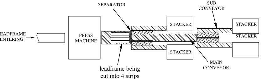
Let us now study Figure 4.2, the next design. A main conveyor is used to transfer the leadframes to their respective small conveyor with the aid of two separators. The separators are use to separate the leadframes further apart and they also prevent leadframes from jamming at the entrance of the small conveyors. The four small conveyors are not placed side by side; instead they are located further from each other. In this way, they can be of bigger size to cater for all the different sizes of leadframe. For this design, the small conveyor does not have to change to run all the defferent sizes of leadframe. As such, there is no need to have so many sizes of conveyors. So this design is very much preferred.
Figure 4.1. Top View of 1st Design
4 conveyors mounted side by side
leadframe being cut into 4 strips
STACKER LEADFRAME ENTERING STACKER STACKER STACKER PRESS MACHINE
Figure 4.2 Top View of 2nd Design
SUB CONVEYOR
STACKER SEPARATOR
leadframe being cut into 4 strips
[image:32.612.113.531.529.656.2]4.3 Finalisation of Design
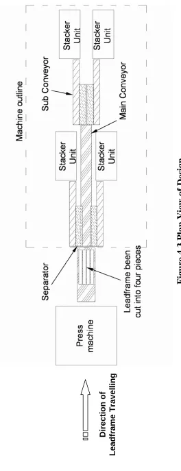
After much simulation using the drawing software, AutoCAD, it was realised that the 1st design is definitely not workable. Since the gap between each leadframe is only 3-4 mm, it is impossible to have a side plate of the conveyor to be 2 mm if they are to be placed side by side. As mentioned earlier, the 2nd design is workable and the final design will base on this concept. This design is made up of one main conveyor, four sub-conveyors and two separators. This design actually incorporates both the powered material handling system and the nonpowered material handling system. The former being the conveyors and the latter refers to the separators. See Figure 4.3 for the final design.
4.3.1 Working Principle
There are basically two processes to the operation: The 1st stage and the 2nd stage.
1st Stage
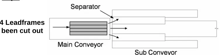
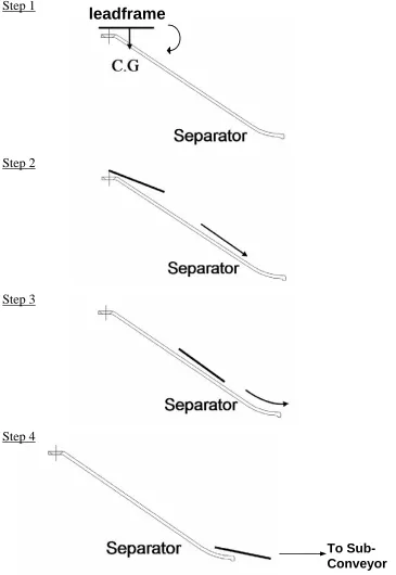
After the long strip of leadframe is being cut out into four leadfames of smaller length and width, they are being transferred out of the press machine by the main conveyor to the 1st separator. Due to the offset of the centre of gravity, the two outermost leadframes will tilt to one side of the separator. Eventually the leadframes slide down the separator due to their own weight. When the leadframes reach the end of the separator, they will drop to the sub-conveyor and then transferred to the stacker unit to stack up. Refer to Figure 4.4 and Figure 4.5.
As for the two centre leadframes, they will start to slide down the plate to the bottom main conveyor when they, together with the two outermost leadframes, reached the end of the top main conveyor. They continue to travel along the main conveyor until they reach the 2nd separators. Refer to Figure 4.4 and Figure 4.6.
Fi
g
ure 4.3 Plan View of Desi
g
n
Direction of
[image:34.612.193.457.57.744.2]Step 1
4 Leadframes been cut out
Step 2
Step 3
To Stacker unit
To 2nd stage
[image:35.612.143.521.106.201.2]To Stacker unit
Step 1
leadframe
Step 2
Step 3
Step 4
[image:36.612.153.518.84.614.2]To Sub- Conveyor
Step 1
Plate
Step 2
Step 3
To 2nd
[image:37.612.141.507.67.611.2]Stage
2nd Stage
When the two central leadframes reach the second separator, their centre of gravity is being offset. So they slide down to the other two sub-conveyors due to gravity. They are then transferred to the allocated stacker respectively for stacking up via the other two sub-conveyors. Refer to Figure 4.7 and Figure 4.8.
In short, the 2nd stage of the process is to separate the final two central leadframes.
4.4 General Approach
After the concept of the design is out, it is then possible to choose the component parts. The selection for the component parts is discussed in Chapter 5.
With the size of all the component parts determined, a detailed assembly of all the parts is drawn out with the aid of AutoCAD software. At this stage, careful attention is needed or else one will encounter a lot of problems during the assembly of the parts. Designers must have a clear mind and be able to visualize any obstruction in fixing up the conveyor system.
After sizing is done and the parts drawing drawn, I need to source for the vendors and get a few quotations for all the parts needed. It is good to find as many vendors as possible during sourcing so that the prices and the lead time for the parts can be compared. Only then can I gauge which one is the most desirable.
Step 1
2 Leadframes From the 1st stage
Step 2
Step 3
To Stacker Unit
[image:39.612.145.516.73.581.2]To Stacker Unit
Step 1
Step 2
Step 3
Step 4
To Small Conveyor
[image:40.612.141.496.80.610.2]To Small Conveyor
The following factors should be observed during the design stage of a component or assembly to reduce corrosion to a minimum:
- The design should avoid crevices and corners where moisture may become trapped, and adequate ventilation should be provided.
- The design should allow for easy washing down and cleaning.
- Joints which are not continuously welded should be sealed, for example by the use of mastic compounds or impregnated tapes.
- Where dissimilar metals have to be joined, high strength epoxy adhesives should be considered since they insulate the metals from each other and prevent galvanic corrosion.
Chapter 5
Selection of Components
A conveyor system is made up of several components. Each of these components plays an important part in the work performances of the conveyor system. Therefore special care should be given when selecting the components.
5.1 Conveyor Belts
The belt is the primary component of a belt conveyor system. It usually represents a substantial part of the initial cost of the system. Since it is such a large investment, proper selection is important to ensure long life. All other systems of a belt conveyor should be designed and built with the purpose of obtaining the longest possible belt life.
5.1.1 Components of a Conveyor Belt
5.1.1.1 Carcass
The carcass performs all of the primary functions of the belt. It provides the tensile strength necessary to move the loaded belt and absorbs the impact forces of material being loaded onto the belt. It also provides lateral stiffness necessary to support the load between idlers and gives adequate strength for mechanical fasteners to hold on to. It is formed by bonding the piles of fabric together with a rubber or polymer skim coat.
5.1.1.2 Breaker
A breaker is a special fabric found on top of the fabric piles. It is used to increase the adhesion between the carcass and the top cover. It can also be designed to increase the impact, heating, and ripping resistance of a belt. Breaker can also increase lateral support.
5.1.1.3 Top Cover
The top cover protects carcass from the material being conveyed. It must absorb abrasive wear at loading and protect the carcass from any adverse property of the material being conveyed. The top cover must also be capable of withstanding any environmental condition it is exposed to.
5.1.1.4 Bottom Cover
Figure 5.1 The Various Components of a Conveyor Belt
In order to confirm the correct type of belt is being considered, it is necessary to have the following information:
- Types of items to be carried. - Width of belt.
- Speed of conveyor. - Total load on belt.
- Size and weight of the largest article.
- Adverse conditions such as the presence of oil, water, dirt and dust, and temperature variations.
5.1.2 Belt Material
Conveyor belt is constructed from a variety of natural and synthetic materials. The trend for the last fifty years has been moving away from natural fibres to the more dependable synthetic fibres. Below are some of the fibres used.
5.1.2.1 Nylon
5.1.2.2 Polyester
Polyester has high strength and exceptionally good abrasion and fatigue resistance. Unlike nylon, it has low moisture absorption, which gives it good dimensional stability. It is also not affected by mildew.
5.1.2.3 Polyurethane
Polyurethane is a unique material that offers the elasticity of rubber combined with the toughness and durability of metal. Polyurethane can reduce plant maintenance cost. Urethanes have better abrasion and tear resistance than rubbers, while offering higher load bearing capacity. Compared to plastics, urethanes offer superior impact resistance, while offering excellent wear properties and elastic memory.
5.1.3 Belt Splice Techniques
Conveyor belt is usually made endless onsite, by either vulcanizing or mechanical fasteners. Of the two techniques, vulcanizing provides the stronger splice. Back when natural fibres and nylon made up the majority of belt carcasses sold, vulcanizing sealed the carcass away from moisture and mildew, prolonging belt life. Mechanical fasteners leave edges exposed. The mechanical splice has gained popularity due to its low cost and ease of installation.
Vulcanizing is still the preferred choice of splice for initial installations and repairs on high-tension belts. For onsite repairs of low-tension belts, mechanical fasteners are more popular.
5.1.3.1 Vulcanized Splice
possible but requires trained personnel and large specialized equipment to be brought onsite. Cold splicing produces a fairly strong bond and is done using a liquid cement and hardener. This can be done by moderately trained personnel. See Figure 5.2.
Step Splice
This technique is normally used with conventional plied carcass construction. It is easily performed with moderately trained personnel using the cold vulcanizing technique.
Skived Splice
This technique must be used on the more complex straight warp or solid woven carcass. It is popular with PVC belting.
Finger Splice
This technique is also used on straight warp and solid woven carcasses. The fingers provide increased bonding area for a stronger splice.
5.1.3.2 Mechanical Splice
Figure 5.2 Types of Vulcanised Belt Splice Techniques
Hinged
Hinged splice can be installed in a shop and quickly joined onsite with the insertion of a hinge rod. The hinge rod can be removed, and one of the sides can be cut and reset. Hinged fasteners also offer the option of attaching a different thickness of belt to one another by hinging different size fasteners together. Hinged fasteners leave small openings that may allow fines to leak through the belt. This type of fastener is popular in mining as splices can be quickly separated or detached when extending the length of a conveyor. See Figure 5.3(a).
Solid plate
(a)
[image:48.612.227.445.78.385.2](b)
Figure 5.3 Types of Mechanical Belt Splice Techniques
Mechanical fasteners can be attached by staple, bolt, or rivet. Rivets are recommended because they damage the belt material the least.
5.1.4 Belt Training
Training or tracking a belt is the process of adjusting various components of a belt system so the belt consistently runs centrally.
If the pulleys are not properly aligned, the belt will run off-centre, so damaging its edges on the structure. Other factors which can cause a belt to wander are: belt not cut perfectly straight, conveyor structure out of line, pulleys not adequately crowned. Some or all of these possibilities make it essential to provide fine adjustment of the pulleys. The bearings or dead-eyes on each side of the pulley must be independently adjustable and should be securely locked in position after adjustment. Various methods are used to adjust roller mountings but the easiest is simply to slot all fixing holes.
5.2 Bearings
Bearings provide support for rotating shafts and allow smooth, low friction motion between two surfaces. Load is applied to these bearings in either a radial or axial direction, or in a combination of these. Radial loads act at right angles to the shaft axis of rotation. Sometimes this radial load is the result of a side load caused by a chain, belt, or gear, and sometimes it is due to gravity alone. Axial (or thrust) load is load applied along the axis of the shaft. If a load is supported by a vertical shaft, then the bearing will experience a thrust load.
Lubricant creates a low friction barrier between the rotating and stationary members, thus minimizing friction. Lubricant in the bearing isolates the shaft and sleeve, preventing metal-to-metal contact.
5.2.1 Parts of Bearing
Bearing usually consists of an outer ring, inner ring, rolling elements (balls or rollers), and a cage which positions the rolling elements at fixed intervals between the ring raceways. See Figure 5.4.
Figure 5.4 Parts of a Bearing
Rolling element bearings require sufficient lubrication to wet the rolling surfaces. Grease is used for most low speed applications. Seals and shields are often used to prevent loss of lubricant and to prevent dirt from getting into the bearing. Sealed bearings have lubrication included at assembly and are not relubricated. Less expensive unground bearings with much greater tolerances can be used for less demanding applications.
5.2.2 Types of Bearing
5.2.2.1 Ball Bearing
Ball bearing is the most popular of all the ball bearing types because it is available in a wide variety of seal, shield and snap-ring arrangements. It can sustain radial, axial, or composite loads and because of simple design, this bearing type can be produced to provide both high-running accuracy and high-speed operation.
5.2.2.2 Roller Bearing
Roller bearing is often used in high-speed applications. Because the inner ring, outer ring, and rollers are in line contact, this bearing type has a large radial load capacity. Since it supports axial loads as sliding action between the end of the rollers and flange faces axial loading is limited.
5.2.2.3 Self-Aligning Bearing
Self-aligning ball bearing is suitable for long shafts where accurate positioning of housing bores is difficult. Due to its special construction, it will tolerate a small angular misalignment from deflection or mounting error.
5.2.2.4 S-Bearing Unit
Ball
Bearing
[image:53.612.149.505.67.228.2]Roller Bearing
Figure 5.5 Types of Bearing
Self-Aligning Bearing
S- Bearing Unit
5.3 Motor and Gearhead
The two primary components of a drive unit are the motor and the gear head. A variety of ancillary equipment may also be required. These devices may provide such functions as speed control, soft starting capability, and overload protection. After having determined the type of conveyor, the next step is to select a drive system. Selection of the drive system is based on the following factors :
- Economics - Space limitations - Starting characteristics
- Ambient atmospheric conditions - Single or variable speed requirements
- Type and voltage of power service available
When selecting a drive train, there is often a multitude of equipment choices and approaches. The difficulty lies in selecting the most appropriate system. Usually, economics is the deciding factor. But in some cases, special requirements or conditions will be the deciding factor.
5.3.1 Types of Motors
There are many types of motors in the market. Below are basically the few types.
5.3.1.1 Basic Motor
Continuous Operation (Induction Motor)
Bi-directional Operation (Reversible Motor)
Reversible motors are capacitor-run induction motor and designed for applications where instantaneous reversal is required. By simple switching, the direction of motor rotation can be reversed frequently between CW and CCW rotation.
5.3.1.2 Brake Motor
If the applications require the motor to stop faster than the above mentioned, brake motor is recommended. With induction motor, it generally takes 30-40 revolution (at the motor shaft) before the motor comes to a complete stop after the switch is turned off. With reversible motor, it takes about 5-6 revolutions. But with brake motor, it is capable to reduce the overrun to just 1-1.5 revolutions. Some can even hold the load in position when the motor is stopped.
5.3.1.3 Speed Control Motor
The speed of the speed control motors can be easily set and adjust by the use of a potentiometer. The control system consists of a speed-feedback system, a motor, a control pack (or a driver) and a potentiometer. This motor is controlled by a closed-loop speed control system.
5.3.1.4 Linear Head Motor
5.3.2 Selection Procedure
During the selection of a motor, there are fundamental criteria involved in the procedure. Below are the steps when selecting small size, standard AC motors such as induction motors and reversible motors:
- Determine the required specifications.
First determine the basic required specification of mechanism and applications such as operating speed, load torque, power supply voltage and frequency.
- Calculate the operating speed and select gearhead.
Induction and reversible motor speeds cannot be adjusted. Motor speed must be reduced with gearheads to match the required machine speed. It is therefore necessary to determine the correct gear reduction ratio.
- Calculate the required torque.
Calculate the required torque and confirm the torque needed for the gearhead.
- Select a motor.
Use the required torque and speed to select a motor and gearhead from the catalogue.
- Check with the starting torque of the motor/ Speed confirmation
5.3.3 Sizing of Motor
Motor need to be carefully selected in order not to oversize or undersize it. Following the selection procedure as mentioned before, calculation of the correct size of motor and gearhead for the main conveyor and the sub conveyor is given as below.
5.3.3.1 Main Conveyor
According to the specification in Appendix , the output for the press machine is 25 to 55 leadframes/min. From this we can find the minimum and maximum belt speed required.
Belt speed is given as below.
V = (Machine Output x Leadframe Length) / 60 cm/sec
∴ Maximum belt speed, V1 = 55 x 25 / 60
= 22.9 cm/sec
∴ Minimum belt speed, V2 = 25 x 25 / 60
Main conveyor specifications:
Total weight, W = 3 kg Friction coefficient of sliding surface, μ = 0.3 Drum diameter, D = 3.2 cm Roller Efficiency, η = 0.9 Angle of Inclination, α = 0°
Belt speed, V1 = 22.9 cm/sec
V2 = 10.4 cm/sec
Input voltage = 200 V/ 50 Hz Direction = uni-direction
a) Calculation of speed at gear shaft.
NG1 = V x 60 / (1 π x D)
= 22.9 x 60 / (π x 3.2) = 136.8 rpm
N = VG2 1x 60 / (π x D)
= 14.6 x 60 / (π x 3.2) = 62.1 rpm
b) Determination of gear ratio.
With 50Hz power supply, torque of speed control motor is greatest at 1300rpm.
i1 = 1300 / NG1
= 1300 / 136.8 = 9.5
i 2 = 1300 / N G2
= 1300 / 62.1 = 20.9
Therefore gear ratio, i, of 9 is chosen. NM1 = NG1x i
= 136.8 x 9 = 1231.2 rpm NM2 = NG2 x i
= 87.1 x 6 = 558.9 rpm
c) Calculation of required torque.
F = Fa + W (sin α + μ cos α ) = Fa + 3 (sin 0 + 0.3 cos 0)
0
= 3 (0.3) = 0.9 kg
Load torque at the gearhead shaft,
TL = (F x D) / (2η)
= 0.9 x 3.2 / (2 x 0.9) = 1.6 kgfcm
Load torque at the motor shaft,
Tm = TL / (i x ηG)
= 1.6 / (9 x 0.73) = 0.24 kgfcm
Considering the fluctuation of power supply, 200% tolerance in the calculation is given as below.
T = 0.24 x 2 m
= 0.48 kgfcm
Based on the specification from Appendix D.4, speed control motor US560-502E is the best choice. Since the reduction ratio is 9, gearhead 5GU9KB is selected.
Then using both the minimum speed and the maximum speed of the speed control unit to determine whether the product selected meets the required specification.
V1 = (Nmax x π x D) / (60 x i)
= (1400 x π x 3.2) / (60 x 9) = 26.1 cm/sec
V2 = (Nmin x π x D) / (60 x i)
= (90 x π x 3.2) / (60 x 9) = 1.7 cm/sec
The selected motor can operate at a higher speed and a lower speed as compared to the required specification. Therefore the motor meets the requirement.
5.3.3.2 Sub Conveyor
Since the speed of the sub conveyor has to be faster than that of the main conveyor so a higher speed need to be assigned to it. Taking that the small conveyor needs to handle 35 to 80 leadframes/min. From this we can find the minimum and maximum belt speed required.
Belt speed is given as below.
V = (Machine Output x Leadframe Length) / 60 cm/sec
∴ Maximum belt speed, V1 = 80 x 25 / 60
∴ Minimum belt speed, V2 = 35 x 25 / 60
= 14.6 cm/sec
Small Conveyor specifications:
Total weight, W = 0.85 kg Friction coefficient of sliding surface, μ = 0.3 Drum diameter, D = 3.2 cm Roller Efficiency, η = 0.9 Angle of Inclination, α = 0°
Belt speed, V1 = 33.3 cm/sec
V2 = 14.6 cm/sec
Input voltage = 200 V/ 50 Hz Direction = uni-direction
d) Calculation of speed at gear shaft.
NG1 = V1 x 60 / (π x D)
= 33.3 x 60 / (π x 3.2) = 198.7 rpm
N = VG2 1x 60 / (π x D)
= 14.6 x 60 / (π x 3.2) = 87.1 rpm
e) Determination of gear ratio.
With 50Hz power supply, torque of speed control motor is greatest at 1300rpm.
i1 = 1300 / NG1
= 1300 / 198.7 = 6.5
i 2 = 1300 / N G2
So to achieve both speeds, smaller gear ratio must be taken. Therefore gear ratio, i, of 6 is chosen.
NM1 = NG1x i
= 198.7 x 6 = 1192.2 rpm
NM2 = NG2 x i
= 87.1 x 6 = 522.6 rpm
f) Calculation of required torque.
F = Fa + W (sin α + μ cos α ) = Fa + 0.85 (sin 0 + 0.3 cos 0)
0
= 0.85 (0.3) = 0.26 kg
Load torque at the gearhead shaft,
TL = (F x D) / (2η)
= 0.26 x 3.2 / (2 x 0.9) = 0.46 kgfcm
Load torque at the motor shaft,
Tm = TL / (i x ηG)
= 0.46 / (6 x 0.73) = 0.11 kgfcm
Considering the fluctuation of power supply, 200% tolerance in the calculation is given as below.
T = 0.11 x 2 m
This required torque is applied to the motor constantly at any speed. Therefore the motor must have a greater torque than 0.22 kgfcm at low and high speed. Based on the specification from Appendix D.4, speed control motor US425-402E is the best choice. Since the reduction ratio is 6, gearhead 4GN6K is selected.
Then using both the minimum speed and the maximum speed of the speed control unit to determine whether the product selected meets the required specification.
V1 = (Nmax x π x D) / (60 x i)
= (1400 x π x 3.2) / (60 x 6) = 39.1 cm/sec
V2 = (Nmin x π x D) / (60 x i)
= (90 x π x 3.2) / (60 x 6) = 2.5 cm/sec
5.4 Belt and Pulley
Belt drives provide an inexpensive means of transferring energy and motion from one rotating shaft to another. Belts are used when large distances between shafts make gears impractical or when the drive speed is too high for chain drives. Belt-drive systems include two shaft-mounted grooved pulleys, one on each shaft, and a belt loop.
Pulleys are used to transmit rotational energy to the various types of belts and they are generally made from steel or aluminium. Pulley width should be approximately 10% wider than the belt. Minimum pulley diameter should be at least 30 times the belt thickness. The shape of the pulley will often take the shape of the belt. This will minimize the slippage between the belt and the pulley.
[image:64.612.203.443.468.684.2]Belt systems often include an idler pulley positioned to provide tension on the belt. Each pulley must be locked to its shaft. The drive pulley is mounted on the drive shaft, usually of an electric motor. The driven pulley is usually larger and has a lower rotational velocity. Figure 5.6 shows the assembly of a belt and pulley.
All belts except timing belts rely on friction between the pulley and the belt to transmit the force from the pulley to the belt. The force is exerted at the driven pulley to cause rotation, thereby transferring the force from one shaft to another. The distance the belt moves in a period of time, the belt velocity, multiplied by the force transferred produces the power supplied and received. Any differences in these quantities represent the inefficiency of the system.
5.4.1 Advantages and Disadvantages
The advantages of belt drives are that they do not require lubrication, they are low maintenance, they dampen and smooth out shock loads, and they provide quiet, smooth operation. Also pulleys are generally less expensive than drive sprockets.
[image:65.612.197.452.420.682.2]The disadvantages of belt drives include load transfer limitations related to friction, a tendency for the belt to stretch, a tendency for the belt to jump from the pulley during shock loading, and inefficiency related to slippage.
5.4.2 Problems with Belt
Problems which often related with belts include slip, stretch, and creep. Slip is caused by a loss of friction between the belt and pulley and is minimized by sufficient belt warp or arc of contact. If slip is prevalent, excessive belt temperature results. Stretch is minimized by internal reinforcement such as with polyester cord. Creep is the tendency of a belt to relax or stretch over time as it moves around the pulley while under load. Figure 5.7 shows the features of a belt.
5.4.3 Types of Belt
The many types of belt include flat, round, V-belt, and Timing belt. Refer to Figure 5.8.
5.4.3.1 Flat Belt
Flat belt was the original type of belt used to transfer power from line shafts operating above the factory floor to individual machines. Flat belts have the capability to provide torque transmission around a corner. This permits connection of nonparallel shafting. To provide necessary friction, flat belts require higher tension belts. Often a slight crown is applied to the pulleys to increase the tension on the belt. This crown also helps the belt stay centered on the pulley. But flat belts are not practical for timing applications where the angular orientation of one shaft relative to another is critical.
5.4.3.2 Round Belt
5.4.3.2 V-Belt
V-belt is used in many industrial applications. Multiple V-belts with parallel belt strands are comparable to chain drives in carrying power. The name V-belt comes from its driving action, which occurs at the tapered sides of the belt rather than across the flat bottom. They generally contain polyester cords to add strength and retard stretching. The tension section carries the load while the compressed section wedges against the pulley groove.
5.4.3.2 Timing Belt
Timing belt is made with teeth molded into the rubber that mesh with teeth in the driving and driven pulleys, producing a positive no-slip drive system permitting timed operation. Steel reinforcement is used in the belt construction to eliminate belt stretch. Tooth shape is usually trapezoidal and many automobile engines use timing belts to synchronize the timing between the crank and the cam shafts of the engine. The primary disadvantage of this type of belt is that it is expensive.
If open-ended belts are used, the ends must be carefully spliced to assure that the belt stays together under load.
5.4.4 Speed Ratio
Fig 5.8 Types of Pulley Belt
5.5 Conveyor Structure
A conveyor is seldom a precision tool and its construction should be robust, and easy to install and maintain. Pressed steel sections are ideal for light duty but frames of standard rolled steel members are more suitable for heavy-duty work.
It is a common practice to mount the shaft in self-aligning ball bearings to allow for the tracking adjustments that must be provided.
5.5.1 Materials
Materials that are often use for building the structure for the conveyors are mild steel rectangular bar or aluminium profile. Conveyor frames should not be designed in a way that requires welding in two directions, i.e. along and across the conveyor.
In this project, aluminium profile is used for making the structure. The reasons are aluminium is light and it is flexible in terms of fixing up. Because of the grooves available on the profile, parts fixing on it can be adjusted freely. This gives it more flexibility in mounting. See Appendix D.7 for more details.
5.5.2 Importance of Flatness
Mounting of cell to structure, the mounting of the cell is done usually by using a plate that is joined to the base of the cell and screw tightly to the structure. Having a flange on the base usually does the tank mounting, as mounting holes are located at the flange.
It is necessary to ensure that the edges of side members at joints are well radiused. If lining materials are used, these too must have radiused or chamfered edges, and all fixing bolts must be well countersunk.
On the whole, we should practice standardizing. Standardizing is the practices of using only one make of equipment and maybe only one or two sizes of that make. This is not always possible in every situation, particularly when custom-made equipment is required. A standard model is chosen based on past successes of certain makes, or the more deliberate approach of experimenting with different manufacturers’ products.
There are numerous advantages to standardizing. For one, spare parts stocking are simplified. The plant need only stock a few spare parts for all the conveyors of the specific make. There is also an advantage in terms of maintenance. The plant personnel become familiar with repair routines, replacement, and lubrication schedules.
Chapter 6
Safety Aspects
Safety measures are very important during the installation and operation of the conveyor system. They must be strongly adhere to in the prevention of incidents.
6.1 Areas to Take Note
Below are some of the areas which I had take note prior to design the conveyor system.
6.1.1 Electricity
Voltage supplies to motor in order for the conveyor to operate.
Problems : - Possibilities of people getting electrocuted if wires not connected properly.
Actions : - Check that wire connections are not exposed. - Make sure the wire is well insulated.
- Cover up the speed controller so that the places near the joints of the connection wires are not accessible.
6.1.2 Belt and Pulley
Using of pulleys and belts to transmit power from the motor to conveyors. Problems : - Hands get caught by the pulleys and belts when motor is running. May cause serious fracture.
Actions : - Attached safety covers to the exposed belts and pulleys. - Stick warning signs to warn operators of the moving parts.
6.1.3 Motor
Prolong usage of conveyors, especially during 24 hrs shift work.
Problems : - Motors get very hot. Hands will get burnt when they are accidentally touched.
Actions : - Attached safety covers with holes for ventilation purpose. - Stick warning signs to warn operators of the moving parts.
- Arrange to run production in an air-conditioned room to cool down the motors faster.
- Stick warning signs to warn operators of the hot parts.
6.1.4 Structure
Prolong usage of conveyors, especially during 24 hrs shift work.
Problems : - Sharp edges and corners of the metal parts can cut people if they are not careful.
Actions : - State in drawing that all sharp edges and corners to be chamfered or rounded.
- Stick warning signs to warn operators of the moving parts.
6.2 General Guidelines
The person in charge must have a thorough knowledge of the following precautions and shall aim for zero incident operations.
In the precaution, the term "Person in charge" refers not only to the person who operates or supervises this system but also engaging directly in production activities; it includes people who maintain and inspect the equipment and all people engaged in work relating to the equipment.
6.2.1 Safety Acts for Assembly and Installation
- Be sure to put on safety equipment like safety shoe and etc.
- When performing assembly and installation, be sure that the parts are clean without any oil stain as it may dirty the products.
- Before performing any works, signboard "Work In Progress" should be put up at the most prominent area where every person can see.
- Before performing any works, secure all doors on the control panel or operating panel.
- Before performing any works, set the main switch to "OFF" position and lock the key, or place a sign saying " DO NOT SWITCH ON " on the main panel.
- If changing of system wiring is necessary, be sure to shut off the power supply. Performing wiring work with the power supply turned on, is danger of electrical shock.
- Assembly and installation, either on electrical or mechanical work, must be done by skilled worker with electrical or mechanical equipment assembly and installation knowledge.
- Inspect the work area surrounding. All unsafe points must take extra measure to ensure safety. In particular, if there are places where footing is inadequate, there is a risk of human injury due to falling.
- Never use gloves if there is a danger of being wound into the rotating parts etc.
- Distinguish component storage location and passageway; do not place things in passageways. There is a risk of injury if people trip over them.
6.2.2 Safety Precaution for Operation Procedures
6.2.2.1 Before Operation
- Check that there are no people go near the rotating mechanism or high temperature parts.
- Never touch any electrical switches with wet hands.
- Cooperative work is required, be sure to signal your partner when starting any operation system
- Do not operate the system with the equipment safety cover removed.
- Carefully check the position and function of switches, buttons and keys before operating any system operation.
- Keep the floor around the equipment organized and clean.
- Do not place any foreign objects on any of the movable mechanism.
- Secured all control or operating panel doors.
- When performing adjustment work, check for one or two completed revolution on all rotating mechanism by hands, to ensure they are not jammed either by foreign metal or driving mechanism itself.
- Remove obstruction around the system
- Check all fasteners are properly tightened.
6.2.2.2 During Operation
- First signal anyone around, before starting the operation.
- Always be alert of any abnormal vibration and noise. Stopped the operation immediately and remedy the fault.
- Do not touch the rotating mechanism when it is running.
6.2.2.3 After Operation
6.2.3 Emergency Act
- Press the emergency stop switch on touch screen panel.
- Follow the checklist stated in general precaution before operation.
- Never operate the system again before any fault is found and remedied.
Chapter 7
Project Performance
After the conveyor system is installed on the stacker machine, several testing is done on the machine itself. Different sizes of leadframe are used for the testing purposes. The samples include the smallest and the largest leadframe that is to be processed during any time of the production and some of the sizes in between the range. The speed of the conveyor is adjusted according to the speed of the stamping machine. For the test run, the speed of the press machine is being put to the low side before the speed is being gradually increase. This is to prevent any serious damage to the machine if the punching tools are not aligned properly.
Separator
[image:78.612.121.514.65.296.2]Can be adjusted
Figure 7.1 Adjustment of the Separator
As for the sliding of the two outer most leadframe, the orientation of the separator can be adjusted to give the best sliding action. It will prevent the leadframe from sliding too fast and damage the edges. It can also prevent leadframe from not sliding down due to not enough tilting angle.
For the 2 middle leadframe, the plate is used as a platform for them to slide to the bottom main conveyor. The position and tilting angle of the plate can be adjusted to aid the sliding action. See Figure 7.2.
Can be adjusted
Figure 7.2 Adjustment of the Plate
7.1 Test Result
A speed of the minimum and the maximun is being tested and leadframes of various width were used for the testing. The testing was conductor for more than six hours. During this period, all the models of the leadframe that is to be run were tested. From the test run, it can be said that the machine is working fine. The test result for all the models tested is tabulated in Table 7.1.
Testing Time Cycle Time (min) (sheet/min)
30 25 Yes 0
30 40 Yes 0
30 55 Yes 0
30 25 Yes 0
30 40 Yes 0
30 55 Yes 0
30 25 Yes 0
30 40 Yes 1
30 55 Yes 0
30 25 Yes 0
30 40 Yes 0
30 55 Yes 1
Compatibility No. of Defects
[image:80.612.129.512.61.267.2]1A 2B 3C 4D No. 1 2 3 4 Model
Table 7.1 Test Result for the Conveyor System
To solve the problem, the tilting angle of the separator is changed to reduce the sliding force. Another way is to place a rubber padding at the side of the conveyor. This will act as a cushion for the leadframe.
7.1 Comparison Test
To further outline the advantages of this new conveyor system, an experiment on two production lines are conducted. The difference of the lines is that one of it uses the new conveyor system while the other uses manpower to collect the products. This experiment was continued for four months. The outcomes of both results were plotted in graphs shown in Figure 7.1 and Figure 7.2.
No. of Defects vs Month
0 5 10 15 20May Jun Jul Aug
[image:81.612.136.518.67.281.2]Manually Conveyor System No. o f D efects Month
Figure 7.1 Test Result for the Conveyor System
60