ScienceDirect
Available online at Available online at www.sciencedirect.comwww.sciencedirect.com
ScienceDirect
Structural Integrity Procedia 00 (2016) 000–000www.elsevier.com/locate/procedia
2452-3216 © 2016 The Authors. Published by Elsevier B.V.
Peer-review under responsibility of the Scientific Committee of PCF 2016.
XV Portuguese Conference on Fracture, PCF 2016, 10-12 February 2016, Paço de Arcos, Portugal
Thermo-mechanical modeling of a high pressure turbine blade of an
airplane gas turbine engine
P. Brandão
a, V. Infante
b, A.M. Deus
c*
aDepartment of Mechanical Engineering, Instituto Superior Técnico, Universidade de Lisboa, Av. Rovisco Pais, 1, 1049-001 Lisboa,
Portugal
bIDMEC, Department of Mechanical Engineering, Instituto Superior Técnico, Universidade de Lisboa, Av. Rovisco Pais, 1, 1049-001 Lisboa,
Portugal
cCeFEMA, Department of Mechanical Engineering, Instituto Superior Técnico, Universidade de Lisboa, Av. Rovisco Pais, 1, 1049-001 Lisboa,
Portugal
Abstract
During their operation, modern aircraft engine components are subjected to increasingly demanding operating conditions, especially the high pressure turbine (HPT) blades. Such conditions cause these parts to undergo different types of time-dependent degradation, one of which is creep. A model using the finite element method (FEM) was developed, in order to be able to predict the creep behaviour of HPT blades. Flight data records (FDR) for a specific aircraft, provided by a commercial aviation company, were used to obtain thermal and mechanical data for three different flight cycles. In order to create the 3D model needed for the FEM analysis, a HPT blade scrap was scanned, and its chemical composition and material properties were obtained. The data that was gathered was fed into the FEM model and different simulations were run, first with a simplified 3D rectangular block shape, in order to better establish the model, and then with the real 3D mesh obtained from the blade scrap. The overall expected behaviour in terms of displacement was observed, in particular at the trailing edge of the blade. Therefore such a model can be useful in the goal of predicting turbine blade life, given a set of FDR data.
© 2016 The Authors. Published by Elsevier B.V.
Peer-review under responsibility of the Scientific Committee of PCF 2016.
Keywords: High Pressure Turbine Blade; Creep; Finite Element Method; 3D Model; Simulation.
* Corresponding author. Tel.: +351 218419991.
E-mail address: [email protected]
2452-3216 © 2016, PROSTR (Procedia Structural Integrity) Hosting by Elsevier Ltd. All rights reserved. Peer review under responsibility of the Scientific Committee of PCF 2016.
10.1016/j.prostr.2016.06.124
Procedia Structural Integrity 2 (2016) 966–973
© 2016, PROSTR (Procedia Structural Integrity) Hosting by Elsevier Ltd. All rights reserved. Peer-review under responsibility of the Scientific Committee of PCF 2016.
10.1016/j.prostr.2016.06.124
Available online at www.sciencedirect.com
Structural Integrity Procedia 00 (2016) 000–000
www.elsevier.com/locate/procedia
21st European Conference on Fracture, ECF21, 20-24 June 2016, Catania, Italy
Experimental techniques for ductile damage characterisation
A. Sancho
a,∗, M.J. Cox
a,b, T. Cartwright
b, G.D. Aldrich-Smith
b, P.A. Hooper
a,
C.M. Davies
a, J.P. Dear
aaImperial College London, Department of Mechanical Engineering, London, SW7 2AZ, United Kingdom bAWE Plc., Materials Science, Aldermaston, Reading, RG7 4PR, United Kingdom
Abstract
Ductile damage in metallic materials is caused by the nucleation, growth and coalesce of voids and micro-cracks in the metal ma-trix when it is subjected to plastic strain. A considerable number of models have been proposed to represent ductile failure focusing on the ultimate failure conditions; however, only some of them study in detail the whole damage accumulation process. The aim of this work is to review experimental techniques developed by various authors to measure the accumulation of ductile damage under tensile loads. The measurement methods reviewed include: stiffness degradation, indentation, microstructure analysis, ultrasonic waves propagation, X-ray tomography and electrical potential drop. Stiffness degradation and indentation techniques have been tested on stainless steel 304L hourglass-shaped samples. A special interest is placed in the Continuum Damage Mechanics ap-proach (CDM) as its equations incorporate macroscopic parameters that can represent directly the damage accumulation measured in the experiments. The other main objective lies in identifying the strengths and weaknesses of each technique for the assessment of materials subjected to different strain-rate and temperature conditions.
c
2016 The Authors. Published by Elsevier B.V.
Peer-review under responsibility of the Scientific Committee of ECF21.
Keywords: Ductile damage; Voids; CDM; Continuum Damage Mechanics; High strain-rate; Elastic modulus; Indentation; Ultrasonic waves; X-ray tomography; Electrical potential drop; DIC; Digital Image Correlation, Stainless steel 304L.
1. Introduction
If a certain threshold plastic strain is achieved in a metallic material, defects like voids and micro-cracks start to nucleate. When further strain is applied they grow up to a point where they interact with each other, leading eventually to a macroscopic crack and fracture. The experimental measurement of this damage is not trivial, and different techniques have been proposed over the years with the aim of characterising ductile damage accumulation. This research is focused on the ductile damage evolution when tensile strain is progressively applied. The diverse techniques for its measurement are reviewed and some of them are tested on hourglass-shaped samples of stainless steel 304L. A methodology to characterise damage is proposed and the results obtained so far are presented.
∗Corresponding author. Tel.:+44-7547-669858.
E-mail address:[email protected]
2452-3216 c2016 The Authors. Published by Elsevier B.V.
Peer-review under responsibility of the Scientific Committee of ECF21.
Available online at www.sciencedirect.com
Structural Integrity Procedia 00 (2016) 000–000
www.elsevier.com/locate/procedia
21st European Conference on Fracture, ECF21, 20-24 June 2016, Catania, Italy
Experimental techniques for ductile damage characterisation
A. Sancho
a,∗, M.J. Cox
a,b, T. Cartwright
b, G.D. Aldrich-Smith
b, P.A. Hooper
a,
C.M. Davies
a, J.P. Dear
aaImperial College London, Department of Mechanical Engineering, London, SW7 2AZ, United Kingdom bAWE Plc., Materials Science, Aldermaston, Reading, RG7 4PR, United Kingdom
Abstract
Ductile damage in metallic materials is caused by the nucleation, growth and coalesce of voids and micro-cracks in the metal ma-trix when it is subjected to plastic strain. A considerable number of models have been proposed to represent ductile failure focusing on the ultimate failure conditions; however, only some of them study in detail the whole damage accumulation process. The aim of this work is to review experimental techniques developed by various authors to measure the accumulation of ductile damage under tensile loads. The measurement methods reviewed include: stiffness degradation, indentation, microstructure analysis, ultrasonic waves propagation, X-ray tomography and electrical potential drop. Stiffness degradation and indentation techniques have been tested on stainless steel 304L hourglass-shaped samples. A special interest is placed in the Continuum Damage Mechanics ap-proach (CDM) as its equations incorporate macroscopic parameters that can represent directly the damage accumulation measured in the experiments. The other main objective lies in identifying the strengths and weaknesses of each technique for the assessment of materials subjected to different strain-rate and temperature conditions.
c
2016 The Authors. Published by Elsevier B.V.
Peer-review under responsibility of the Scientific Committee of ECF21.
Keywords: Ductile damage; Voids; CDM; Continuum Damage Mechanics; High strain-rate; Elastic modulus; Indentation; Ultrasonic waves; X-ray tomography; Electrical potential drop; DIC; Digital Image Correlation, Stainless steel 304L.
1. Introduction
If a certain threshold plastic strain is achieved in a metallic material, defects like voids and micro-cracks start to nucleate. When further strain is applied they grow up to a point where they interact with each other, leading eventually to a macroscopic crack and fracture. The experimental measurement of this damage is not trivial, and different techniques have been proposed over the years with the aim of characterising ductile damage accumulation. This research is focused on the ductile damage evolution when tensile strain is progressively applied. The diverse techniques for its measurement are reviewed and some of them are tested on hourglass-shaped samples of stainless steel 304L. A methodology to characterise damage is proposed and the results obtained so far are presented.
∗Corresponding author. Tel.:+44-7547-669858.
E-mail address:[email protected]
2452-3216 c2016 The Authors. Published by Elsevier B.V.
Structural Integrity Procedia 00 (2016) 000–000
www.elsevier.com/locate/procedia
21st European Conference on Fracture, ECF21, 20-24 June 2016, Catania, Italy
Experimental techniques for ductile damage characterisation
A. Sancho
a,∗, M.J. Cox
a,b, T. Cartwright
b, G.D. Aldrich-Smith
b, P.A. Hooper
a,
C.M. Davies
a, J.P. Dear
aaImperial College London, Department of Mechanical Engineering, London, SW7 2AZ, United Kingdom bAWE Plc., Materials Science, Aldermaston, Reading, RG7 4PR, United Kingdom
Abstract
Ductile damage in metallic materials is caused by the nucleation, growth and coalesce of voids and micro-cracks in the metal ma-trix when it is subjected to plastic strain. A considerable number of models have been proposed to represent ductile failure focusing on the ultimate failure conditions; however, only some of them study in detail the whole damage accumulation process. The aim of this work is to review experimental techniques developed by various authors to measure the accumulation of ductile damage under tensile loads. The measurement methods reviewed include: stiffness degradation, indentation, microstructure analysis, ultrasonic waves propagation, X-ray tomography and electrical potential drop. Stiffness degradation and indentation techniques have been tested on stainless steel 304L hourglass-shaped samples. A special interest is placed in the Continuum Damage Mechanics ap-proach (CDM) as its equations incorporate macroscopic parameters that can represent directly the damage accumulation measured in the experiments. The other main objective lies in identifying the strengths and weaknesses of each technique for the assessment of materials subjected to different strain-rate and temperature conditions.
c
2016 The Authors. Published by Elsevier B.V.
Peer-review under responsibility of the Scientific Committee of ECF21.
Keywords: Ductile damage; Voids; CDM; Continuum Damage Mechanics; High strain-rate; Elastic modulus; Indentation; Ultrasonic waves; X-ray tomography; Electrical potential drop; DIC; Digital Image Correlation, Stainless steel 304L.
1. Introduction
If a certain threshold plastic strain is achieved in a metallic material, defects like voids and micro-cracks start to nucleate. When further strain is applied they grow up to a point where they interact with each other, leading eventually to a macroscopic crack and fracture. The experimental measurement of this damage is not trivial, and different techniques have been proposed over the years with the aim of characterising ductile damage accumulation. This research is focused on the ductile damage evolution when tensile strain is progressively applied. The diverse techniques for its measurement are reviewed and some of them are tested on hourglass-shaped samples of stainless steel 304L. A methodology to characterise damage is proposed and the results obtained so far are presented.
∗ Corresponding author. Tel.:+44-7547-669858.
E-mail address:[email protected]
2452-3216 c2016 The Authors. Published by Elsevier B.V.
Peer-review under responsibility of the Scientific Committee of ECF21.
2 A. Sancho et al./Structural Integrity Procedia 00 (2016) 000–000
The work introduced here corresponds to the initial stages of a broader research project whose aim is to study ductile damage accumulation under different temperature and strain-rate conditions. Some considerations on further work required to address these topics are discussed, as well as their connection to the current work.
1.1. Ductile Damage Phenomenon
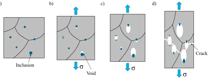
Plastically deformed material remains internally undamaged until the phenomenon called ductile damage takes place. The underlying physics of this problem involve the creation of microscopical voids and micro-cracks within the metal matrix following three different phases: nucleation, growth and coalesce of these micro-cavities (Fig. 1).
Voids appear near crystalline defects such as inclusions, solution precipitates or added particles in alloys, when a large local deformation occurs in their vicinity. Locally, a stress concentration appears near the defect causing plastic deformation. The combination of plastic deformation and stress state cause a fracture of the defect or its decohesion from the metal matrix (depending on the relative brittleness of the defect), nucleating in both cases a void or a micro-crack (Lemaitre and Chaboche (1990)). The external loading conditions required to generate this instability are generally higher than the yield condition, and therefore, ductile damage starts after a certain plastic strain has macroscopically accumulated in the material.
If the cavity is subjected to further plastic strain it increases its size, reducing internally the net resisting section of the component. When voids reach a certain size they interact with other neighbouring defects, eventually leading to the macroscopic failure known as ductile fracture.
1.2. Ductile Damage Models
Damage models try to predict the amount of damage produced by ductile voids that is accumulated within the material once it starts to yield. Coupling an elasto-plastic model with a damage model, a thorough prediction of the eventual failure of a structure, as well as its progressive degradation, can be obtained.
The elastic behaviour of the material can generally be represented with just two parameters, the elastic modulus and the elastic limit. For highly demanding applications the plastic regime is nowadays also addressed as a usable region of materials, and plastic models have been derived to represent the flow stress versus plastic strain curve. The most powerful plastic models are those that consider the effect that strain-rate and temperature produce on the plastic curve, like those proposed by Johnson and Cook (1983) or Zerilli and Armstrong (1987).
Several approaches have been proposed in an attempt to model ductile damage, each of them leading to a number of damage models developed by different authors. The first group is that of the micro-mechanical models, which try to represent directly the nucleation-growth-coalesce behaviour of voids. Rice and Tracey (1969) proposed a model based on an isolated spherical void within an infinite uniform medium of perfectly plastic material affected by a remote tensile field and hydrostatic stresses; while Gurson (1977) derived the equations of a simplified continuum porous material, where the ductile damage can be obtained from a void density parameter (f), instead of studying discrete voids.
Inclusion a)
σ
Void b)σ
c)σ
[image:2.544.104.455.538.671.2]Crack d)
968 A. Sancho et al. / Procedia Structural Integrity 2 (2016) 966–973
A. Sancho et al./Structural Integrity Procedia 00 (2016) 000–000 3
The second approach is the Continuum Damage Mechanics method (CDM), where the defects are not studied individually; alternatively, damage is quantified throughout the macroscopic effects it produces on the material. In these models an expression for damage is derived from the thermodynamic laws of irreversible processes. Kachanov (1986) set the foundations of this technique that has largely been extended by authors like Lemaitre and Desmorat (2005) and Bonora. These authors proposed CDM models for ductile damage based on a linear (Lemaitre (1985)) and a logarithmic (Bonora (1997)) accumulation of damage, respectively.
The last group of models is the empirical approach. These models are generally focused on predicting material fracture rather than on characterising the evolution of damage. An expression for the equivalent plastic strain to failure (eq,fp ) is proposed and material failure is considered when the equivalent plastic strain reaches that value (eqp =eq,fp ).
The model calibration consists in fitting the proposed ductility curve to the experimentally obtained fracture data. Some relevant models of this type are Johnson and Cook (1985) and Xue and Wierzbicki (2008).
All the damage models described include parameters that are dependent on the material and the testing conditions, and that need to be calibrated if the model is to be used. The number of parameters that the model includes varies, being easier to calibrate accurately those models with a limited number of parameters. The CDM approach has been chosen as reference technique since is has a consistent physical and thermodynamic background, the number of parameters involved in its models is reduced and these parameters have a physical meaning, which implies that they can be directly obtained from experimental measurements.
2. Techniques for Ductile Damage Measurement
The measurement of ductile damage throughout a tensile test is a challenge since it is not a directly measurable material property as stress or strain are. Nevertheless, different techniques have been proposed in an attempt to monitor damage accurately. All the techniques measure a property which is linked somehow to the development of voids in the material, and from which damage history can later be derived.
The stiffness or elastic modulus reduction measurement is the most commonly used technique to obtain ductile damage. The method has largely been developed and discussed by Lemaitre and Dufailly (1987) and Bonora et al. (2011). It consists on the subsequent measurement of an effective elastic modulus ( ˜E) performing partial elastic unloadings in a tensile test, and on the comparison of those values with the initial elastic modulus (E). The decrease in modulus can be associated to the progressive loss in load carrying capacity of the material caused by the reduction in net resisting section due to the increase in area occupied by voids. Most authors have used strain gauges to obtain elastic modulus, nevertheless, these have a limited plastic elongation range and have to be replaced throughout the test. Continuous measuring alternatives such as extensometers and DIC (Digital Image Correlation) can also be employed. Hardness evaluation by means of indentation as a method to obtain damage has the same theoretical principles of elastic modulus reduction technique. The applied load and indentation depth are recorded throughout the test and from the unloading slope elastic modulus, and therefore, ductile damage can be obtained. The technique proposed by Oliver and Pharr (1992) is generally used to do this post-processing. The use of indentation to measure damage was proposed by Lemaitre and Dufailly (1987) and later used by Guelorget et al. (2007), Tasan et al. (2012) or Zhang et al. (2014). The method can be very accurate locally, making it powerful when localisation starts and other techniques lack of accuracy; nonetheless, it is quite tedious to perform due to sample preparation requirements.
The study of micrographic SEM pictures was mentioned by Lemaitre and Dufailly (1987) as a method to measure damage through the comparison of the area fraction that corresponds to voids and micro-cracks to the total area observed. Other authors like Tasan et al. (2012) have used the technique for this purpose, but they report a reasonably low accuracy, as the very small measuring region increases the statistical error.
The response of a material to input ultrasonic pulses can be used to investigate the density of voids and internal defects by the measurement of ultrasonic phase velocity or pulse attenuation. The elastic modulus of the material can be obtained from the values of longitudinal and shear wave velocity, which can be experimentally measured using longitudinal and shear ultrasonic transducers respectively, as exposed by Boccaccini (1997). This method is mentioned by Lemaitre and Dufailly (1987), but has not been largely applied to damage characterisation, although it seems promising specially for high strain-rate applications.
X-ray micro-tomography technique can be used to obtain the internal volume of voids of a sample which has undergone a certain level of plastic strain. The technique consists in taking 2D X-ray scans of the sample from
different circumferential positions, and through post-processing, reconstruct the internal 3D features of the sample to measure void density, average diameter or shape. This information was used by Cao et al. (2014) to calibrate the GNT micro-mechanical model.
The electrical resistance of the material can also be related to the resisting area, and therefore, to the ductile damage. The lower net cross-section generated by the appearance of voids produces an electrical resistance increase when a certain current is going through the material. If the sample is loaded in tension and this increase in resistance monitored ductile damage can be obtained. The technique was presented by Lemaitre and Dufailly (1987), and used by authors like Kumar et al. (2009) to calibrate CDM models. Zhang et al. (2014) combined it with DIC to calculate the damage field in the whole sample gauge length.
All these techniques have been considered as part of this work, and the first two have already been put into practice, producing a methodology for ductile damage characterisation of metals. Some of the other techniques will be tested in the future for validation or comparison purposes, or if they present an advantage for the high strain-rate experiments.
3. Materials and Methodology
3.1. Stainless Steel 304L
The material investigated in this study is stainless steel 304L, which is a common austenitic steel with high chromium content (minimum 18%) and low carbon content (maximum 0.03%). The geometries tested are hourglass-shaped tensile specimens both round and flat. This geometry has been selected in order to concentrate damage in the central part of the specimen, and therefore ensure that maximum damage and eventual failure is localised there. The flat samples were machined in the rolling direction from a laminated plate of 3 mm of thickness, while the round samples were turned from a drawn bar of 12 mm of diameter. Both geometries have a small central gauge length of 6 mm where the section is uniform and where measurements have been taken; thereafter, the hourglass shape starts.
3.2. Procedure for ductile damage characterisation
In order to characterise ductile damage of a material, a general methodology has been set, consisting of four steps:
• Plastic Characterisation:
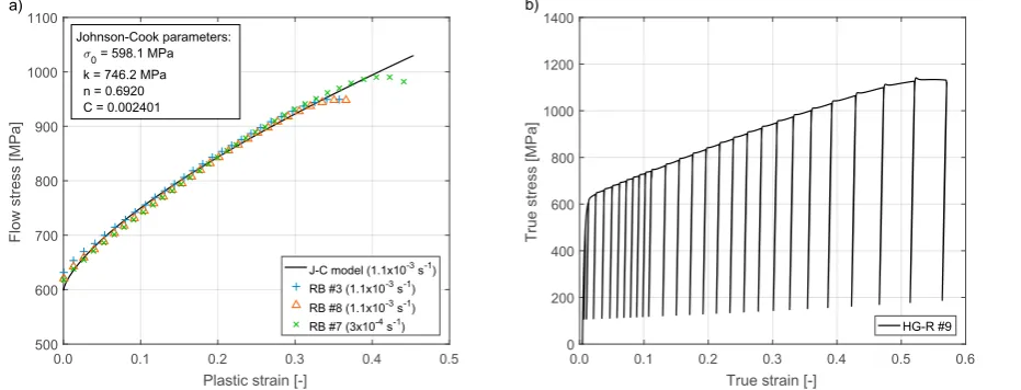
The first step consists in the classic stress-strain characterisation of the material. Since the study is focused on damage and it only appears when the material deforms plastically, the interest is primarily focused on modelling the plastic region of the material. As presented above, variation of strain-rate and temperature will be studied at a later stage of the project, and therefore, a plastic model that presents these two conditions as variables has been selected. In this case, Johnson and Cook (1983) model has been chosen for the analysis. Fig 2(a) shows the result of the Johnson-Cook plastic model calibration for three round bar tensile specimens tested at room temperature and at two different strain-rates, both in the quasi-static regime.
• Damage Measurement:
The key step of the process implies the measurement of ductile damage at progressive stages of plastic strain. To accomplish it, one of the techniques presented above should be used. In the present study the elastic modulus reduction technique has been employed and later compared with the results given by the indentation technique. Both the round and flat specimens have been tested following this technique in a 250 kN Instron tensile ma-chine at room temperature and quasi-static strain-rate conditions. Progressive partial unloadings have been programmed, as presented in Fig. 2(b). The strain in the central region of the sample has been measured using an extensometer of 6 mm gauge length and+6 mm/-0.3 mm travel. In one of the flat samples the strain has been monitored using 3D DIC, contemplating it as a possible alternative for stiffness calculation.
970 A. Sancho et al. / Procedia Structural Integrity 2 (2016) 966–973
A. Sancho et al./Structural Integrity Procedia 00 (2016) 000–000 5
0.0 0.1 0.2 0.3 0.4 0.5
Plastic strain [-] 500
600 700 800 900 1000 1100
Flow stress [MPa]
J-C model (1.1x10⁻³ s-1)
RB #3 (1.1x10⁻³ s-1)
RB #8 (1.1x10⁻³ s-1)
RB #7 (3x10⁻⁴ s-1)
a)
Johnson-Cook parameters: <0 = 598.1 MPa k = 746.2 MPa n = 0.6920 C = 0.002401
0.0 0.1 0.2 0.3 0.4 0.5 0.6
True strain [-] 0
200 400 600 800 1000 1200 1400
True stress [MPa]
HG-R #9
b)
Fig. 2. (a) True stress vs. true plastic strain experimental data of three round bar tensile experiments and Johnson-Cook plastic model calibration; (b) true stress vs. true strain history of one of the damage measurement experiments using the elastic modulus reduction technique.
• Stress Triaxiality Analysis:
As noted above, apart from the applied equivalent plastic strain, the hydrostatic stress has a considerable effect on the development of voids and ductile damage. Therefore, for the accurate characterisation of damage this effect should be considered through an analysis of the ductility for different levels of hydrostatic stress (normally represented by means of the stress triaxiality factor, which is the ratio of hydrostatic stress to equivalent von-Mises stress). This is typically done by testing round notched bar specimens of different notch radius. In this geometry, each notch radius can be associated to a certain value of fairly constant triaxiality factor as given by Bridgman (1952); and therefore, by testing different notch geometries the effect of stress triaxiality on ductility is characterised. Being this a preliminary study, the triaxiality analysis has not been performed yet, but tests on round notched bars are planed for the future.
• Damage Characterisation:
The final step is the damage model calibration using all the experimental data acquired. The methodology proposed by Bonora et al. (2004) has been used as a guideline for the fitting process. After fitting the data obtained in the previous steps, the set of parameters of the model is obtained and the model can be used for material damage prediction. For example, running it in combination with a finite elements code where the plastic model calibrated in the first step has also been included, plastic stresses, strains and ductile damage can be obtained along the simulation.
4. Results
4.1. Elastic Modulus Technique
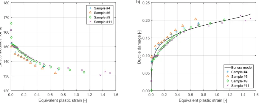
Fig. 3 shows the results of 304L round samples, while Fig. 4 presents those of 304L flat samples. Fig. 3(a) and 4(a) present the measured degradation of the elastic modulus of the material as a function of the equivalent plastic strain, and Fig. 3(b) and 4(b) the evolution of ductile damage with equivalent plastic strain.
The round samples (Fig. 3) present a prominent initial increase of damage (decrease of stiffness) at rather low values of equivalent plastic strain,eqp. Thereafter, the damage accumulates fairly linearly up to necking. This behaviour can
[image:5.544.39.505.86.264.2]0.0 0.1 0.2 0.3 0.4 0.5 Plastic strain [-]
500 600 700 800 900 1000 1100
Flow stress [MPa]
J-C model (1.1x10⁻³ s-1)
RB #3 (1.1x10⁻³ s-1)
RB #8 (1.1x10⁻³ s-1)
RB #7 (3x10⁻⁴ s-1)
a)
Johnson-Cook parameters: <0 = 598.1 MPa k = 746.2 MPa n = 0.6920 C = 0.002401
0.0 0.1 0.2 0.3 0.4 0.5 0.6
True strain [-] 0
200 400 600 800 1000 1200 1400
True stress [MPa]
HG-R #9
b)
Fig. 2. (a) True stress vs. true plastic strain experimental data of three round bar tensile experiments and Johnson-Cook plastic model calibration; (b) true stress vs. true strain history of one of the damage measurement experiments using the elastic modulus reduction technique.
• Stress Triaxiality Analysis:
As noted above, apart from the applied equivalent plastic strain, the hydrostatic stress has a considerable effect on the development of voids and ductile damage. Therefore, for the accurate characterisation of damage this effect should be considered through an analysis of the ductility for different levels of hydrostatic stress (normally represented by means of the stress triaxiality factor, which is the ratio of hydrostatic stress to equivalent von-Mises stress). This is typically done by testing round notched bar specimens of different notch radius. In this geometry, each notch radius can be associated to a certain value of fairly constant triaxiality factor as given by Bridgman (1952); and therefore, by testing different notch geometries the effect of stress triaxiality on ductility is characterised. Being this a preliminary study, the triaxiality analysis has not been performed yet, but tests on round notched bars are planed for the future.
• Damage Characterisation:
The final step is the damage model calibration using all the experimental data acquired. The methodology proposed by Bonora et al. (2004) has been used as a guideline for the fitting process. After fitting the data obtained in the previous steps, the set of parameters of the model is obtained and the model can be used for material damage prediction. For example, running it in combination with a finite elements code where the plastic model calibrated in the first step has also been included, plastic stresses, strains and ductile damage can be obtained along the simulation.
4. Results
4.1. Elastic Modulus Technique
Fig. 3 shows the results of 304L round samples, while Fig. 4 presents those of 304L flat samples. Fig. 3(a) and 4(a) present the measured degradation of the elastic modulus of the material as a function of the equivalent plastic strain, and Fig. 3(b) and 4(b) the evolution of ductile damage with equivalent plastic strain.
The round samples (Fig. 3) present a prominent initial increase of damage (decrease of stiffness) at rather low values of equivalent plastic strain,eqp. Thereafter, the damage accumulates fairly linearly up to necking. This behaviour can
be attributed to a significant early formation of voids in the metal matrix when the threshold strain,th, is surpassed
0.0 0.2 0.4 0.6 0.8 1.0 1.2 1.4 1.6
Equivalent plastic strain [-] 120
130 140 150 160 170 180
Elastic modulus [GPa]
Sample #4 Sample #6 Sample #9 Sample #11
a)
0.0 0.2 0.4 0.6 0.8 1.0 1.2 1.4 1.6
Equivalent plastic strain [-] 0.00
0.05 0.10 0.15 0.20 0.25
Ductile damage [-]
Bonora model Sample #4 Sample #6 Sample #9 Sample #11
b)
Fig. 3. (a) Elastic modulus vs. equivalent plastic strain and; (b) ductile damage vs. equivalent plastic strain experimental data of four hourglass-shaped round bar specimens under interrupted tensile tests and preliminary Bonora (1997) model calibration.
0.0 0.2 0.4 0.6 0.8 1.0
Equivalent plastic strain [-] 120
130 140 150 160 170 180
Elastic modulus [GPa]
Sample #19 Sample #20 Sample #13 (DIC)
a)
0.0 0.2 0.4 0.6 0.8 1.0
Equivalent plastic strain [-] 0.00
0.05 0.10 0.15 0.20 0.25
Ductile damage [-]
Sample #19 Sample #20 Sample #13 (DIC)
b)
Fig. 4. (a) Elastic modulus vs. equivalent plastic strain and; (b) ductile damage vs. equivalent plastic strain experimental data of four hourglass-shaped flat specimens under interrupted tensile tests.
(eqp > th). As the strain is further increased, new voids may appear at a lower almost constant rate, and at the same
time, the existing voids grow in size also at a rate fairly proportional to the applied strain. This process continues up to necking and failure when the equivalent plastic strain reaches its critical value,cr(th < eqp < cr). In Fig.3(b) a
preliminary calibration of Bonora (1997) model is also plotted.
[image:6.544.54.489.83.256.2] [image:6.544.53.489.321.497.2]972 A. Sancho et al.A. Sancho et al. / Procedia Structural Integrity 2 (2016) 966–973/Structural Integrity Procedia 00 (2016) 000–000 7
0 5 10 15 20
Distance to fracture section [mm]
380 390 400 410 420 430 440 450 460
Hardness Vickers 10 [-]
a)
0 5 10 15 20
Distance to fracture section [mm] 0.0
0.1 0.2 0.3 0.4 0.5
Ductile damage [-]
90 100 110 120 130 140 150
Elastic modulus [GPa]
Ductile damage Elastic modulus
b)
Fig. 5. (a) Vickers10 hardness measurements vs. longitudinal distance from the fracture region; (b) elastic modulus and ductile damage vs. longi-tudinal distance from the fracture region. Error bars represent the standard deviation based on 4 indentations per section.
4.2. Indentation Technique
Fig. 5 presents the results of the preliminary study of indentation technique. These are plotted as a function of the distance to the fracture section in the loading direction. A uniaxial study has therefore been considered for the time being. In Fig. 5(a) Vickers 10 kg hardness values are plotted for different positions; and in Fig. 5(b) the elastic modulus and ductile damage values obtained using the Oliver and Pharr (1992) method are represented along the loading direction.
It can be observed that the region closer to the fracture section has been greatly hardened as a consequence of the high density of dislocations generated in the vicinity of the fractured section (Cotterell et al. (2002)), whereas hardness decreases when moving away from this location, eventually reaching the value of the undamaged material if measurements are taken far enough. The change in slope around 6 mm corresponds to the section where the specimen changes from uniform section to progressively increasing section (hourglass-shape). The behaviour of damage is also the expected, with high values near the necked fracture section that progressively decrease.
5. Discussion and Further Work
The results obtained with the elastic modulus reduction technique are generally consistent and accurate for the round specimens. However, the flat samples presented much noisier results, probably caused by the extensometer strain measurements, as flat knifes were used leading to a linear contact between sample and knifes, instead of the desired point contact. As not all the points in the contact line present the same strain a certain error is expected, sug-gesting that an improved attachment arrangement would be desirable. The results obtained with the DIC technique present similar accuracy, being the noise caused in this case by the inherent accuracy limits of the technique. Conse-quently, it can hardly be improved and it can be concluded that DIC may not be accurate enough to measure elastic modulus within reasonable error limits.
[image:7.544.43.503.78.258.2]0 5 10 15 20 Distance to fracture section [mm]
380 390 400 410 420 430 440 450 460
Hardness Vickers 10 [-]
a)
0 5 10 15 20
Distance to fracture section [mm] 0.0
0.1 0.2 0.3 0.4 0.5
Ductile damage [-]
90 100 110 120 130 140 150
Elastic modulus [GPa]
Ductile damage Elastic modulus
b)
Fig. 5. (a) Vickers10 hardness measurements vs. longitudinal distance from the fracture region; (b) elastic modulus and ductile damage vs. longi-tudinal distance from the fracture region. Error bars represent the standard deviation based on 4 indentations per section.
4.2. Indentation Technique
Fig. 5 presents the results of the preliminary study of indentation technique. These are plotted as a function of the distance to the fracture section in the loading direction. A uniaxial study has therefore been considered for the time being. In Fig. 5(a) Vickers 10 kg hardness values are plotted for different positions; and in Fig. 5(b) the elastic modulus and ductile damage values obtained using the Oliver and Pharr (1992) method are represented along the loading direction.
It can be observed that the region closer to the fracture section has been greatly hardened as a consequence of the high density of dislocations generated in the vicinity of the fractured section (Cotterell et al. (2002)), whereas hardness decreases when moving away from this location, eventually reaching the value of the undamaged material if measurements are taken far enough. The change in slope around 6 mm corresponds to the section where the specimen changes from uniform section to progressively increasing section (hourglass-shape). The behaviour of damage is also the expected, with high values near the necked fracture section that progressively decrease.
5. Discussion and Further Work
The results obtained with the elastic modulus reduction technique are generally consistent and accurate for the round specimens. However, the flat samples presented much noisier results, probably caused by the extensometer strain measurements, as flat knifes were used leading to a linear contact between sample and knifes, instead of the desired point contact. As not all the points in the contact line present the same strain a certain error is expected, sug-gesting that an improved attachment arrangement would be desirable. The results obtained with the DIC technique present similar accuracy, being the noise caused in this case by the inherent accuracy limits of the technique. Conse-quently, it can hardly be improved and it can be concluded that DIC may not be accurate enough to measure elastic modulus within reasonable error limits.
It is interesting to compare the results from Fig. 4(b) and 5(b), i.e. the damage obtained through elastic modulus measurement and through indentation. For the elastic modulus technique the damage measured just before failure is around 0.20 – 0.25. As the indentations have been performed over one of the fractured flat samples, the measured damage values correspond to the strain to failure condition. Fig. 5(b) shows a damage value higher to that obtained with the elastic modulus technique near the fracture section (around 0.44), and about 0.25 at a distance of 6 mm. This is the position where the extensometer was installed, and therefore, the results with both techniques are quite
consistent, only highlighting the fact that damage values are underestimated for the elastic modulus technique when the sample starts necking and the stress-strain fields are no longer uniform.
It must be noted that the parameters obtained from the calibration of the plastic and damage models may change with temperature and strain-rate, the future aim of this research project being to analyse that effect. The elastic modulus reduction technique is appropriate for quasi-static tests, nevertheless, it may be a challenge to apply it to high strain-rate tests. This is the main driving force to develop a more suitable technique for such problem. It is the intention to develop a rig capable of interrupting the high strain-rate tests for further study of the material at intermediate levels of strain. Some of the experimental techniques explained above, such as ultrasonic waves and potential drop, are also being studied as non-interrupted damage measurement alternatives.
Acknowledgements
This research was supported by AWE Plc. We are thankful to our colleagues Keith Warburton and Nigel Park who provided expertise that greatly assisted the research.
References
Boccaccini, D.N., Boccaccini, A.R., 1997. Dependence of Ultrasonic Velocity on Porosity and Pore Shape in Sintered Materials. Journal of Non-destructive Evaluation 16, 187–192.
Bonora, N., 1997. A Nonlinear CDM Model for Ductile Failure. Engineering Fracture Mechanics 58(1-2), 11–28.
Bonora, N., Gentile, D., Pirondi, A., 2004. Identification of the Parameters of a Non-Linear Continuum Damage Mechanics Model for Ductile Failure in Metals. Journal of Strain Analysis 39(6), 639–651.
Bonora, N., Ruggiero, D., Gentile, D., De Meo, S., 2011. Practical Applicability and Limitations of the Elastic Modulus Degradations Technique for Damage Measurements in Ductile Metals. Strain 47(3), 241–254.
Bridgman, P.W., 1952. Studies in Large Plastic Flow and Fracture, McGraw-Hill, New York.
Cao, T.S., Maire, E., Verdu, C., Bobadilla, C., Lasne, P., Montmitonnet, P., Bouchard, P.O., 2014. Characterization of Ductile Damage for a High Carbon Steel using 3D X-ray Micro-tomography and Mechanical Tests - Application to the Identification of a Shear Modified GTN Model. Computational Materials Science 84, 175–187.
Cotterell, M., Schambergerova, J., Ziegelheim, J., Janovec, J., 2002. Dependence of Micro-hardness on Deformation of Deep-drawing Steel Sheets. Journal of Materials Processing Technology 124, 293–296.
Guelorget, B., Francois, M., Lu, J., 2007. Micro-indentation as a Local Damage Measurement Technique. Materials Letters 61(1), 34–36. Gurson, A.L., 1977. Continuum Theory of Ductile Rupture by Void Nucleation and Growth: Part I - Yield Criteria and Flow Rules for Porous
Ductile Media. Journal of Engineering Materials and Technology 99(1), 2–15.
Johnson, G.R., Cook, W.H., 1983. A Constitutive Model and Data for Metals Subjected to Large Strains, High Strain-Rates and High Temperatures. Proceedings of the 7th International Symposium on Ballistics, The Hague, Netherlands, 541–547.
Johnson, G.R., Cook, W.H., 1985. Fracture Characteristics of Three Metals Subjected to Various Strains, Strain-Rates, Temperatures and Pressures. Engineering Fracture Mechanics 21(1), 31–48.
Kachanov, L.M., 1986. Introduction to Continuum Damage Mechanics, Springer Science & Business Media, Springer Netherlands.
Kumar, J., Padma, S., Srivathsa, B., Vyaghreswara Rao, N., Kumar, V., 2009. Evolution of Damage in NearαIMI-834 Titanium Alloy under Monotonic Loading Condition: A Continuum Damage Mechanics Approach. Journal of Engineering Materials and Technology 131(3), 031012-1–031012-6.
Lemaitre, J., 1985. A Continuous Damage Mechanics Model for Ductile Fracture. Journal of Engineering Materials and Technology 107(1), 83–89. Lemaitre, J., Dufailly, J., 1987. Damage Measurements. Engineering Fracture Mechanics 28(5-6), 643–661.
Lemaitre, J., Chaboche, J.L., 1990. Mechanics of Solids Materials, Cambridge University Press, Cambridge. Lemaitre, J., Desmorat, R., 2005. Engineering Damage Mechanics, Springer, Berlin Heidelberg New York.
Oliver, W.C., Pharr, G.M., 1992. An Improved Technique for Determining Hardness and Elastic Modulus using Load and Displacement Sensing Indentation Experiments. Journal of Materials Research 7(6), 1564–1583.
Rice, J.R., Tracey, D.M., 1969. On the Ductile Enlargement of Voids in Triaxial Stress Fields. Journal of the Mechanics and Physics of Solids 17(3), 201–217.
Tasan, C.C., Hoefnagels, J.P.M., Geers, M.G.D., 2012. Identification of the Continuum Damage Parameter: An Experimental Challenge in Mod-elling Damage Evolution. Acta Materialia 60(8), 3581–3589.
Xue, L., Wierzbicki, T., 2008. Ductile Fracture Initiation and Propagation Modelling Using Damage Plasticity Theory. Engineering Fracture Me-chanics 75(11), 3276–3293.
Zerilli, F.J., Armstrong, R.W., 1987. Dislocation-Mechanics-Based Constitutive Relations for Material Dynamics Calculations. Journal of Applied Physics 61(5), 1816–1825.