Fault analysis of an active LVDC distribution network for utility applications
Full text
Figure

![Fig. 7. Diagram of DC/DC Bidirectional Converter [30]](https://thumb-us.123doks.com/thumbv2/123dok_us/1566035.109196/3.595.305.538.147.275/fig-diagram-dc-dc-bidirectional-converter.webp)


Related documents
In future LVDC distribution networks, fault current limiting technologies are likely to be widely utilised, and the proposed protection solution in this paper will be more
To reduce the fault current of a modular multilevel converter based dc solid-state transformer, active fault current control is proposed, where the dc and ac
Existing DC breaker technologies include: electromechanical, hybrid and solid state devices, whereas fault current limiting AC/DC converter topologies can be
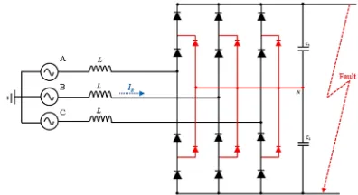
When a two-level or modular multilevel voltage source converter undergo a DC fault, the fault absorbs large current from the AC side once the DC voltage drops
Figure 5.7: Waveform at without three phase fault in power system (i) voltage and current of line (ii) Reactive power (iii) Measure and reference voltage (iv) DC voltage of shunt
By using the measured voltage and current data from both ends of the faulted DC line, the proposed fault location formulas can calculate the location of the fault
Reduced terminal capacitance and extra DC impedance are used to limit DC fault current and reduce the required converter current rating for medium power
Figure 5, Figure 6 and Figure 7 represents the voltage waveform, current at fault point and voltage of power side, respectively on fault phase and non-fault phase without SFCL to