A methodology for design of lightweight robotic arm links in harsh environments
Mr Thomas A. M. McMastera*, Prof. Xiu T. Yana
a Department of Design, Manufacture and Engineering Management, University of Strathclyde, Glasgow, Scotland,
UK, G1 1XQ, thomas.mcmaster@strath.ac.uk * Corresponding Author
Abstract
A methodology for the creation of functionally graded material (FGM) parts in harsh environments has been developed. It uses a two-stage optimisation approach that focusses first on the task-dependent material choice and then on the topological optimisation (TO) of the part. Constraints are in place to ensure the part can be manufactured, including the extent/smoothness of material blending and the minimum feature size and layer thickness. Thought is also put into space-specific concerns, such as radiation and cyclic thermal heating. The methodology assumes an initial design solution has already been generated, and covers from the beginning of the CAD phase to the end of the computational testing phase. Design constraints are created with additive manufacture (AM) in mind, and suggestions are made for material mixing processes for FGM, material layout strategies and manufacturability, including scanning strategies and surface finish.
Keywords: Lightweight, Additive Manufacture, Topology Optimisation, Methodology, Robotic Arm
1. Introduction
Lightweight design is crucial in today’s world to improve efficiencies, reduce costs and bring benefits to the environment. The use of robots is ever-increasing in various sectors of society, from use in industry to use in the home. There is therefore a need to understand how to extract the greatest benefit from robots as possible, including making them as light as possible. Work on lightweight robotic design has featured heavily on re-design of actuators and drive systems [1]–[3][4]–[6]. Links have not received as much attention [7]. The aim of this paper is to outline a methodology for the design of lightweight robotic arm links. The methodology has mechanisms for the inclusion of graded materials. Graded materials allow the designer to combine materials to take advantage of their different material properties. Advantages range from different densities to allow certain regions to be made from lighter materials, to different thermal conductivities to allow for different heat flow characteristics. The methodology differs from previous functionally graded material (FGM) methodologies ([8][9][10]), as it designs parts with the manufacturing constraints already in mind, rather than retro fitting the methodology around current parts.
2. Methodology Overview
The methodology assumes a design task is already in place. The first step is to elicit the design requirements and analyse the form (S1). Once done, the design task must be validated (S2), as this must be well defined before the part is modelled in CAD software (S3). Once
modelled, the part must be split up for assigning graded materials (S4). This is a step exclusive to FGM production, and thus marked in red in Figure 1, along with the theoretical material mixing in the next step (S5). Materials are chosen in the following step (S6). At this stage (S7), the part has enough information to be tested using FEA software. Techniques for graded material mixing (another exclusive FGM step) are discussed in the following section (S8) before suggestions for manufacture are made in the final stages (S9 and S10).
3. Breakdown of Methodology
3.1 Influence of Form
Before work on the form can be done, the design task must be read. The design task describes what the part is expected to do. The first step (S1.1) is to draw the design requirements from this, such as the reach of the arm link and the payload it will carry.
Figure 1: Methodology Overview
Figure 2: "Influence of Form" flowchart
The performance of circular, elliptical and rectangular cross sections is measured. These cross sections are chosen as they perform well in both bending and torsion – the two main forces on a robotic arm link. The circular cross section behaves consistently, independent of
orientation. The elliptical and rectangular cross sections either outperform or underperform the circular cross section, dependent on this orientation. To find this “breakeven orientation angle”, equation 1 (for the rectangle) is used:
α = cos−1(√
12I
bd − b2
d2− b2) (1)
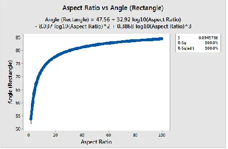
[image:2.612.158.226.70.333.2]Where “I” is the second moment of area, “b” is the breadth and “d” is the depth. This equation is the result of combining the identities for the second moments of area for the circle and rectangle. At the breakeven orientation angle, the arm link has the same mass and stiffness as a circular cross section. Above the breakeven angle, the mass stays the same, while the stiffness increases. Figure 3 shows the output of this equation.
Figure 3: Analysing the AR
When AR<10, the orientation angle varies significantly. Above 10, the influence of AR diminishes. A part with an AR of 10 or above would become very large in one dimension. For these two reasons, an AR of 10 (orientation range of ±70°) is set as a constraint.
Therefore, if the orientation range is greater than 140°, the arm cross section should be circular (S1.2 (a)). If below 140°, the arm section should be elliptical or rectangular (S1.2 (b)). An elliptical cross section with a range of 140° is shown in Figure 4.
[image:2.612.314.543.303.453.2]from failure due to plastic yield to failure due to local buckling. The maximum bending factor (and thus greatest shape efficiency) is given by:
(ϕBe)max≈ 2.3 (
E σf)
1 2 ⁄
(2)
Where E is the Young’s modulus and σf is the yield
strength.
Each cross sectional shape has a different ϕBe value, as listed in [11]. Plugging the values into equation (2) gives the maximum radius to thickness ratio the arm link can have without locally buckling.
[image:3.612.125.262.422.562.2]Ideally, the cross section will have no acute angles in it (to reduce stress concentrations – S1.4). If acute angles exist, they should be rounded.
Figure 4: 140° Orientation Range
3.2 Understanding Design Task
Figure 5: Understanding Design Task
With the design requirements found in step S1 and an initial form decided, validation of the design task is now done (step S2.1). To do this, an equation modelling a cantilever beam is used. The acceleration term is split to represent torque acceleration and gravity acceleration:
x = m(at+ ag)L
3
3EI (3)
Where “x” is the required accuracy of the tip of the arm, “m” is the payload, “at” is the acceleration due to
motor torque, “ag” is the acceleration due to gravity, “L”
is the arm length, “E” is the modulus of elasticity of the material and “I” is the second moment of area of the arm link. When more than one material is being used in the arm link, the modulus of elasticity value is the interpolation of the two constituent material values. If the design requirements elicited from the design task pass this equation, step S1 is finished. However, if when the values from the design task are plugged into equation (3) and the accuracy (x) output is not as required by the design task, the first step is to alter the form. If this is already optimal (as dictated by the steps in S1) the next step is to loosen the least feasible non-compulsory design requirement. This is repeated until equation (3) is satisfied. Depending on the harsh environment, certain parameters will be more important than others. For example, if working in space, the effects of microgravity will mean that weight becomes less of an issue but accuracy will increase in importance (as some arms are very large, such as Canadarm [12]).
3.3 Part Modelling
A CAD model of the robotic arm link is made at the part modelling stage. This step can only take place once the form of the arm link has been finalised.
At this stage, a decision as to whether cellular structures or topology optimisation (T.O) will be used must be made (S3.1).
Cellular structures can only be used if all the following constraints are met:
• Arm link must have at least four orders of rotational symmetry
• Loading must be symmetric (orientation range greater than 140°)
• Distance between two outer skins must be constant AND between 3mm and 15 mm.
This decision is significant to the design – if making an arm link with cellular structures, the cellular structures must be modelled at this stage (using circular/grid patterns). If using T.O., the arm link must be left as “blank” as possible – that is, it should be a solid piece, with only essential features accurately modelled (fixing points, etc). This means the design space is as flexible as possible for the T.O solver. Once this decision is finalised, the CAD model can be made (S3.2).
The following constraint must be fulfilled:
• Minimum feature size of three times the minimum feature size of the AM technology This will ensure that any feature will be sufficiently strong.
objects inside the arm link (wiring, etc) and provide bonding surfaces for the cellular structures or TO design.
Figure 6: "Part Modelling" flowchart
The CAD design must be a watertight model, with no under-defined features. If not watertight, extra definitions must be created on the model until it is watertight.
3.4 Part Segmentation
[image:4.612.109.276.98.345.2]Part segmentation is the first FGM-specific stage in the methodology. The first step (S4.1) is to define the “FGM extremity distance”, seen in Figure 7.
Figure 7: FGM Extremity Distance
This is the maximum distance that the FGM will be created over – typically one end of the arm link to the other. Once this is defined, an FGM extremity distance line can be plotted (S4.2).
The segmentation is done in two directions to allow for material gradation in both directions, if need be. The segmentation must follow two constraints (S4.3):
• Segmentation direction 1 must be perpendicular to the FGM extremity distance line
• Segmentation direction 2 must follow the longest contour on the part which is NOT an FGM extremity contour
Figure 8: "Part Segmentation" flowchart
This is shown in Figure 9. The purple lines show the first constraint, the green lines show the second constraint. These constraints ensure two things: 1) that the material will grade in the same direction as the environment (e.g, temperature) and 2) that each layer has constant material composition. Each area in Figure 9 represents a segment of unique material composition (SUMC) – an area where the material composition is constant, but different to any other area in the arm link. The material composition in a SUMC is the percentage value of the distance along the FGM extremity distance for both materials. Similar to the technique used in Step S1.2, the material properties for each SUMC are the interpolated values of the constituent materials.
Figure 9: FGM Segmentation Constraints
A final constraint is also put in place to ensure the smoothest blending of materials (and thus lowest stress concentrations) while ensuring manufacturability:
• Each SUMC must have a thickness which is exactly divisible by the AM minimum resolution (must be ≥3).
[image:4.612.321.544.466.539.2]3.5 Theoretical Material Mixing
There are several theoretical mixing constraints that must be followed (S5.1):
• Mixing must be to the nearest 0.5%
• Each SUMC layer must be at least three times the AM minimum resolution
• Each SUMC layer must have an integer number of AM minimum resolution layers within
• Materials must mix from a relative 100% of material A to a relative 100% of material B
• There must be as many SUMC layers as possible, with a maximum of 200 (due to the 0.5% mixing constraint)
Figure 10: "Theoretical Mixing" Flowchart
The overall blending distance is the next piece of information needed (S5.2). This is the distance that blending will occur over – not necessarily the FGM extremity distance (if the two faces are not parallel to one another – see Figure 11).
Figure 11: "Overall Blending Distance" compared to the "FGM Extremity Distance"
Depending on this distance, the arm link will have layers which change by 0.5% between each layer (above complete FGM distance) or layers which change by more than 0.5% between each layer (below complete FGM distance). Layer stacking rules (S5.4) are therefore needed. When there are ≥200 SUMCs, each 0.5% layer is stacked sequentially. However, when there are <200 SUMCs, the SUMCs with different percentage alterations have to be stacked in a particular sequence. The SUMCs in minority are placed at equal intervals along the length of the arm link, between the SUMCs in majority.
With current technology, the mixing of carbon fibre composite (fibres and matrix) with a third material is not feasible – the two constituents must be kept separate. To create an arm link that had 200 SUMCs, the total arm would be 12 m minimum in length. It is unexpected that any arm will be that length, hence non-homogeneous FGM design is not considered.
3.6 Material Choice
Choosing materials for the arm link is heavily dependent on the task of the arm. The first step (S6.1) is to convert the design requirements from S1.1 into material properties. This gives the constraints and objectives in terms of materials. The second step (S6.2) is to populate materials charts. The materials on the chart are only those which can be created using AM, as this is the technology that will be used to create the arm link. Two separate material charts are created (S6.3), based on manufacturability - in either group, all materials can be bonded to one another. One chart contains metals and composite fibres; the other contains polymers and composite fibres. One of the constraints in S5.1 stated that “materials must mix from a relative 100% of material A to a relative 100% of material B”. Therefore, there will be equal levels of both constituent materials in the FGM area of any arm link. As such, for a first approximation, materials that will be combined are represented on the material charts as average values of their properties (modulus of elasticity, density, etc).
[image:5.612.104.281.245.440.2] [image:5.612.82.282.548.665.2]on the chart will be: M = E^(1/2)/ρ. Once this is done, the final material can be read off the chart (S6.6).
Figure 12: "Material Choice" Flowchart
3.7 Computational Testing
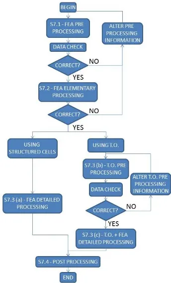
The first computational testing step (S7.1) is setting up the FE pre-processor with all relevant information already generated, including segmented CAD model, materials and loading conditions. This data is validated. If incorrect, alterations must be made. Once correct, the part is then coarsely meshed (S7.2). If results are as expected, work can continue. If not, alterations must be made in the pre-processor (most likely mistakes made in loading/boundary conditions). If the arm link is created with structured cells, the mesh is refined to the minimum AM resolution size, and the simulation run again with identical loading conditions to those used before (S7.3 (a)).
If T.O. is being used, pre-processing must be undertaken (S7.3 (b)). All variables which influence the arm should be included in the analysis. One shall be set as the objective function (the volume to minimise the mass), while the others will be set as absolute scalar values (displacement) while others will be minimised (natural frequency). Geometric restrictions (fixing points, internal and external skins) need defined to ensure the optimisation solver does not remove compulsory material. The T.O. input data should be validated at this stage to ensure the test will succeed.
Once the input data is correct, the mesh can be refined and the solver can be run (S7.3 (c)). The final stage (S7.4) is post processing. For structured cells, this is a simple FE test to ensure the part behaves as it should do. If the part deforms more/less than desired, the thickness of the structural cells can be increased/decreased, and the part re-tested. For T.O parts, the model should be smoothed
in preparation for manufacture and the final part re-tested in FE to ensure it conforms to the design requirements. The smoothing process may increase the mass from the minimum value found during the T.O cycle, however, it will reduce the stress concentrations that would have existed in the part immediately after T.O due to rough surface finishes.
3.8 Actual Material Mixing
This stage of the methodology is theoretical. The material mixing technique depends on the FGM extremity distance. If this is greater than the complete FGM distance possible with the AM technology being used (given by 200 x 3 x AM minimum resolution), “staged” (more accurate) mixing must be used. If the extremity distance is less than the complete distance, “continuous” (less accurate) mixing can be used.
Figure 13: "Computational Testing" Flowchart
[image:6.612.106.265.100.296.2] [image:6.612.349.521.289.573.2]Figure 14: "Physical Material Mixing" Flowchart
When under the complete FGM distance, each material changes its composition by at least 0.5%, (each layer is rounded to the nearest 0.5%, as stated by the constraint in step 5.1). Larger composition alterations between SUMCs do not need mixing to be as accurate to ensure gradation occurs as intended. For this reason, “continuous” mixing can be used. This is based on work by Muller et al [8][9][10], which calculates the delay in the deposition system (S8.2) and uses P.I controllers to correct for it (S8.3). This allows a constant flow of
material to the deposition head; however, the compositions are not as accurate compared to “staged” mixing.
3.9 Manufacturing: Processing
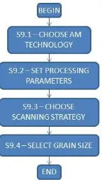
3.9.1 Choosing AM Technology
[image:7.612.71.283.68.312.2]The choice of technology (step S9.1) is both pre-emptive and permissive – minimum feature size is needed before the CAD modelling can begin (pre-emptive) while the choice of material dictates what technologies can and cannot be used (permissive). However, a large dictator in the decision is technology availability – many AM machines require significant financial investment, and the final choice may come down to realistic availability. Table 1 shows the parameters of several established AM technologies, and their suitability for use when creating a multi-material part.
3.9.2 Processing Parameters
Process parameters (laser power, scan speed, etc) must fully consolidate the powders of both materials, without damaging (e.g, overheating) any area. This is the reason material choice is split into two categories in step 6.3. Processing parameters will be set to fully consolidate the material with the higher melt temperature (step S9.2). Laser power will remain constant; however, scan speed will be reduced as the percentage of the higher melt temperature material increases. The slower scan speed will give the energy source more time to consolidate the higher melt temperature material.
Table 1: AM Technology Suitability
Technology Material Groups
Minimum Resolution
Multi Material Ability
Surface Finish
Lightweight Arm Link Suitability
SLS Metals,
Polymers, Ceramics
≈ 100 µm 2 Medium/High High
EBM Metals ≈ 300 µm 1 Medium Medium
LENS Metals,
Ceramics
≈ 100 µm 2 Medium High
FDM Polymers,
Ceramics
≈ 100 µm 3 Low Low
SLA Polymers
(Ceramics)
< 1 µm 3 High High
3DP Metals,
Polymers, Ceramics
[image:7.612.93.526.498.688.2]Figure 15: "Manufacturing: Processing" Flowchart
3.9.3 Scanning Strategies
The scanning strategy (step S9.3) can impart different mechanical properties and heat profiles into a part. For a FGM, the scanning path should complete each SUMC (or layer of SUMCs, if every SUMC in a layer have equal material composition) before moving onto the subsequent one. This will keep materials composition and process parameter changes to a minimum, reducing stress concentrations. If the arm link is large, the island scanning strategy is recommended within in SUMC, due to its low thermal gradient [13]. However, many arm links will have features too small to warrant the island scanning strategy – a straight forward spiral or unidirectional scan strategy will be used.
3.9.4 Thermal Gradient
The thermal gradient in the arm link is also affected by the technology used. Those which use an electron beam create lower thermal gradients, as the building substrate can be preheated in the vacuum, compared to those which use a laser (where preheating is not possible). Again, this decision may come down to realistic availability of AM technology.
3.9.4 Grain Size
Grains of material should be as small as possible to increase the theoretical density of the arm link (step S9.4). As part density increases, so does UTS, another benefit of smaller grain size. The grain size also minimises the staircase effect. There is a practical limitation to the grain size – once too small, cohesive forces impede grain flow. Grains cluster as they do not have enough mass to transport across the surface, and surface finish decreases.
3.10 Manufacturing: Post Processing
Post processing is required for three reasons:
- Remove support structures
- Further consolidate part (increase density) - Improve surface finish
Figure 16: "Manufacturing: Post Processing" Flowchart
Depending on the technology used, support structures (including loose powder) will need to be removed (step S10.1). Removal processes depend on the geometry of the arm link and/or the materials used for support – often they are soluble in solutions that the primary materials are inert towards.
Post processing consolidation (step S10.2) can be done using isostatic pressing. This pressure on the part increases the relative density. However, care must be taken not to damage complex features of parts, such as would be seen on the arm link.
Surface finish can be improved (step S10.3) using numerous methods, the most basic being sanding and polishing. Chemical treatments can be used for certain materials (polymers), but care must be taken that they do not weaken the arm link. Isostatic pressing, at a lower pressure than that used for increasing the density, is also used to improve surface finish.
4. Discussion and Conclusion
[image:8.612.149.221.73.200.2]suitable structure must be chosen. This depends on the loading conditions of the arm link. The first of the constraints to ensure consistent quality manufacture is also implemented here – the minimum feature dimension must be a multiple (≥3) of the minimum resolution of the AM technology being used. The use of AM in this methodology allows complex geometries to be created. These geometries are far more complex than those that could be created using more established manufacturing techniques, such as machining. However, the research showed that there are challenges between what is physically possible and what the underlying ideas in this methodology could produce. This is the reason that constraints are put in place. The demonstration of FGM in this paper differs from some others as it constrains the blending variability between each subsequent segment, as well as the size of the segments themselves – it is a finite blending method. These two constraints ensure that the arm link can be produced with current technology. The fourth step (S4) describes how to segment an arm link for FGM materials. It is important to differentiate between SUMC layers and AM layers. The two are intertwined, but very much distinct. Because mixing is constrained to 0.5% increments, there can be, at most, 200 SUMC layers. The thickness of each SUMC layer is dictated by the AM technology - it has been decided that there must be at least 3 AM deposition layers of any SUMC layer. Most AM technology has a minimum resolution of 0.1 mm, therefore most SUMC layers have a minimum thickness of 0.3 mm. However, each SUMC layer can have many AM layers - it is not limited to three. Indeed, many arm links will have 30 or 40 AM layers within each SUMC layer, as many arm links will be upwards of a metre in length. The material composition within each SUMC is constant – another constraint to ensure quality manufacture is possible. The segmentation rules in step S4 ensure that segments remain of a similar size. One downside of ensuring manufacturability is the increased stress concentrations that will appear because blending is not as smooth as theoretically possible (it is not altered at each gauss point within each finite element [14]. This was an issue that the research highlighted – the challenge between what is physically manufacturable and what could be possible if the methodology was written to take advantage of the theoretical possibilities of the concepts within (FGM blending, multi-material choices). The main objective of step S5 is to calculate the change in material composition between each SUMC. Calculations are used to determine if the change between each SUMC will be 0.5%, or higher (at increments of 0.5%). This constraint on the increment change is to ensure that physical material mixing will be possible – any lower, and accurate levels of each constituent material would be difficult to achieve.
Step S6 sets out how to choose materials. This technique can be implemented on any lightweight part. A large
limitation is the list of materials AM can reliably produce. As this list is relatively short, certain lightweight materials cannot be chosen. In the future as more materials become commercially available for AM, more FGM options will become available. A second limitation is the combination of dissimilar materials – evidence has shown this is possible, but extensive testing has not happened. The process of screening and ranking materials is well established [11]. This methodology uses the “traditional” blending approach of keeping each finite element a constant material value, rather than the “theoretical FGM” approach of altering material properties at gauss points within finite elements. The first assumption of interpolating material properties will be altered in future work.
Step S7 describes the computational testing procedure. The largest difficulty with this step is to correctly identify all forces on the arm link and ensure all units are compatible with one another. This is the reason for the repeated data checks. The researcher has developed a script for segmenting the arm link and assigning materials. All work is applicable to the ABAQUS FE solver. The outputs from the T.O solver are geometrically complex; however, the inputs from the designer are fairly straightforward. As mentioned in section 3.7, the designer only needs to input basic information (objective functions, geometric restrictions). Due to this simplicity, limited discussion is given, despite the fact the step is very important. The solver itself uses the SIMP method. Intuition on behalf of the arm link designer is needed to choose the appropriate mesh sizes.
The methodology has been verified up until the end of step S7 on two case studies, which show promising results.
Step S8 demonstrates how the materials will be physically mixed. Research into rheology is well established – mixing powders with paddles and air is currently done in other fields. The limitation to this method is the additional time it will take when compared to the “continuous” method outlined on the right-hand side of Figure 14.This method was written by Muller et al [9][15], and showed promise, however it is not as precise as pre-mixing materials in a separate hopper, as done on the left hand side of Figure 14.
Suggestions for manufacture are made in the final two steps (S9 - S10), however, these decisions are often constrained by technology availability. Bar suggestions on the choice of AM technology, all steps are generic additive manufacture “good practice”, as at this stage, the methodology-specific steps have finished.
allows the researcher to realise the greater potential of FGMs when compared to using more traditional manufacturing methods. The benefit of being able to incorporate FGMs with T.O is a further benefit of using AM.
5. Future Work
Future work will focus on creating physical parts. These parts can then be tested, and the complete methodology verified. Current weak points in the methodology are as follows:
- The assumption that the material property of any SUMC is the interpolation of the properties of the materials that constitute the SUMC. This assumption should be replaced with an alternative method. Remove material property combination first assumption
- The combination of dissimilar materials. The combinations need testing to validate whether they are structural or not.
6. Acknowledgements
This work acknowledges funding from the following sources: Engineering and Physical Sciences Research Council (EPSRC) Grant No. EP/IO15698/1, University of Strathclyde (including the faculty of engineering and the department of design, manufacture and engineering management (DMEM)) and the China Academy of Launch Vehicle Technology (CALT).
References
[1] A. Albu-Schäffer, S. Haddadin, C. Ott, A. Stemmer, T. Wimböck, and G. Hirzinger, “The DLR lightweight robot: design and control concepts for robots in human environments,” Ind. Robot An Int. J., vol. 34, no. 5, pp. 376–385, 2007.
[2] A. Albu-Schaffer and G. Hirzinger, “State feedback controller for flexible joint robots: A globally stable approach implemented on DLR’s light-weight robots,” IEEE Int. Conf. Intell. Robot. Syst., vol. 2, pp. 1087–1093, 2000. [3] A. Albu-Schäffer, O. Eiberger, M. Fuchs, M.
Grebenstein, S. Haddadin, C. Ott, A. Stemmer, T. Wimböck, S. Wolf, C. Borst, and G. Hirzinger, “Soft Robotics: From Torque Feedback Controlled Lightweight Robots to
Intrinsically Compliant Systems,” Robot. Res., vol. 70, pp. 185–207, 2011.
[4] P. Chedmail and M. Gautier, “Optimum Choice of Robot Actuators,” J. Manuf. Sci. Eng., vol. 112, no. 4, pp. 361–367, 1990.
[5] M. Pettersson and J. Ölvander, “Drive Train Optimization for Industrial Robots,” IEEE Trans. Robot., vol. 25, no. 6, pp. 1419–1424, 2009. [6] L. Zhou, S. Bai, and M. R. Hansen, “Design
optimization on the drive train of a light-weight robotic arm,” Mechatronics, vol. 21, no. 3, pp. 560–569, 2011.
[7] L. Zhou and S. Bai, “A New Approach to Design of a Lightweight Anthropomorphic Arm for Service Applications,” J. Mech. Robot., vol. 7, no. 3, pp. 31001-31001–12, 2015.
[8] P. Mognol, P. Muller, and J. Y. Hascoet, “Functionally Graded Material (FGM) Parts: From Design To The Manufacturing Simulation,” Proc. ASME 2012 11th Bienn. Conf. Eng. Syst. Des. Anal., pp. 1–9, 2012. [9] P. Muller, J. Y. Hascoët, and P. Mognol, “A
Method for the Manufacturing of Functionally Graded Material Parts,” Adv. Mater. Res., vol. 698, pp. 117–126, 2013.
[10] P. Muller, P. Mognol, and J. Y. Hascoet, “Modeling and control of a direct laser powder deposition process for Functionally Graded Materials (FGM) parts manufacturing,” J. Mater. Process. Technol., vol. 213, no. 5, pp. 685–692, 2013.
[11] M. F. Ashby, “Materials Selection in Mechanical Design,” Design, p. 624, 2005.
[12] B. A. Aikenhead, R. G. Daniell, and F. M. Davis, “Canadarm and the space shuttle,” J. Vac. Sci. Technol. A Vacuum, Surfaces, Film., vol. 1, no. 2, pp. 126–132, 1983.
[13] J.-P. Kruth, J. Deckers, E. Yasa, and R. Wauthle, “Assessing and comparing influencing factors of residual stresses in selective laser melting using a novel analysis method,” Proc. Inst. Mech. Eng. Part B J. Eng. Manuf., vol. 226, no. 6, pp. 980– 991, 2012.
[14] W. G. Buttlar, G. H. Paulino, and S. H. Song, “Application of graded finite elements for asphalt pavements,” J. Eng. Mech., vol. 132, no. 3, pp. 240–249, 2006.