UNIVERSITI TEKNIKAL MALAYSIA MELAKA
DEVELOPMENT OF SMART UNDER AND OVER VOLTAGE
PROTECTION SYSTEM FOR DOMESTIC APPLICATION
USING MICROCONTROLLER
This report submitted in accordance with requirement of the Universiti Teknikal Malaysia Melaka (UTeM) for the Bachelor Degree of Engineering Technology
(Industrial Power) (Hons.)
by
SITI MASTURA AINAA BINTI MOKHTAR B071310004
840926-01-6500
UNIVERSITI TEKNIKAL MALAYSIA MELAKA
BORANG PENGESAHAN STATUS LAPORAN PROJEK SARJANA MUDA
TAJUK: Development of Smart Under and Over Voltage Protection System for Domestic Application Using Microcontroller
SESI PENGAJIAN: 2015/16 Semester 2
Saya SITI MASTURA AINAA BINTI MOKHTAR
mengaku membenarkan Laporan PSM ini disimpan di Perpustakaan Universiti Teknikal Malaysia Melaka (UTeM) dengan syarat-syarat kegunaan seperti berikut:
1. Laporan PSM adalah hak milik Universiti Teknikal Malaysia Melaka dan penulis. 2. Perpustakaan Universiti Teknikal Malaysia Melaka dibenarkan membuat salinan untuk
tujuan pengajian sahaja dengan izin penulis.
3. Perpustakaan dibenarkan membuat salinan laporan PSM ini sebagai bahan pertukaran antara institusi pengajian tinggi.
4. **Sila tandakan ( )
SULIT
TERHAD
TIDAK TERHAD
(Mengandungi maklumat yang berdarjah keselamatan atau kepentingan Malaysia sebagaimana yang termaktub dalam AKTA RAHSIA RASMI 1972)
(Mengandungi maklumat TERHAD yang telah ditentukan oleh organisasi/badan di mana penyelidikan dijalankan)
Disahkan oleh:
__________________________
Cop Rasmi:
Tarikh:
** Jika Laporan PSM ini SULIT atau TERHAD, sila lampirkan surat daripada pihak berkuasa/organisasi berkenaan dengan menyatakan sekali sebab dan tempoh laporan PSM ini perlu dikelaskan sebagai SULIT atau TERHAD.
__________________________
Alamat Tetap:
11, Jalan Sri Aman
Taman Muzaffar Syah
75450 Ayer Keroh, Melaka
i
DECLARATION
I hereby, declared this report entitled “Smart Under and Over Voltage Protection System for Domestic Application Using Microcontroller” is the results of my own
research except as cited in references.
Signature : ……….
Author’s Name : SITI MASTURA AINAA BINTI MOKHTAR
ii
APPROVAL
This report is submitted to the Faculty of Engineering Technology of UTeM as a partial fulfilment of the requirements for the degree of Bachelor of Electrical Engineering Technology (Industrial Power) with Honours. The member of the supervisory is as follow:
……….………
iii
ABSTRAK
iv
ABSTRACT
v
DEDICATION
To my beloved husband
Nabil Fikri bin Aziz
Son and baby
Daniyal Haziq bin Nabil Fikri
Mother
Masyati binti Mail and Jamelah binti Baba
Father
Mokhtar bin Saad
Siblings
Siti Masiah ‘Awatif binti Mokhtar
Siti Musliha Ajmal binti Mokhtar
Siti Mashanis Aliya binti Mokhtar
Iza Nuriza binti Aziz
vi
ACKNOWLEDGEMENT
vii
TABLE OF CONTENT
Declaration i
Approval ii
Abstrak iv
Abstract v
Dedication vi
Acknowledgement vi
Table of Content vii
List of Tables x
List of Figures xi
List of Abbreviations, Symbols and Nomenclature xiii
CHAPTER 1: INTRODUCTION
1.0 Background of Project 1
1.1 Problem Statement 2
1.2 Objectives of Project 2
1.3 Scopes of Project 3
1.4 Organization of Report 3
1.5 Summary 4
CHAPTER 2: LITERATURE REVIEW
2.0 Introduction 5
2.1 Theory: Overview of Under and Over Voltage 5 2.1.1 Definition of Under and Over Voltage 5
2.1.2 Causes of Over Voltage 6
2.1.2.1 External Over Voltage 7
2.1.2.2 Internal Over Voltage 9
2.1.3 Causes of Under Voltage 10
2.2 Literature Review: Previous Study on Under and Over Voltage Protection 11 2.2.1 Hardware Implementation of Overvoltage and Under
viii 2.2.2 Implementation of Single Phasing, Over Voltage, Under
Voltage Protection of Three Phase Appliances without
Using Microcontroller 13
2.2.3 Development of a Low Cost Microcontroller Based Under and
Over Voltage Protection Device 15
2.2.4 Under and Over Voltage Protection with Sequential
Tripping Function 17
2.2.5 An Automatic Mains Voltage Switch Protector for
Domestic Appliances 20
2.2.6 Double Relay Based Sag, Swell, Over and Under Voltage
Protection and Detection Scheme 22
2.3 Summary 23
CHAPTER 3: METHODOLOGY
3.0 Introduction 24
3.1 Research Flow 25
3.2 Software Development 26
3.2.1 Schematic Circuit 26
3.2.2 Coding 28
3.2.3 Burning Coding to the Microcontroller 30
3.3 Hardware Development 31
3.3.1 Operation of the Circuit 32
3.3.2 Devices and Components Used in the Circuit 32
3.3.2.1 Isolator Switch 32
3.3.2.2 Step Down Transformer 33
3.3.2.3 Diode 35
3.3.2.4 Resistor 36
3.3.2.5 Microcontroller 37
3.3.2.6 Capacitor 39
3.3.2.7 Liquid Crystal Display 39
3.3.2.8 Transistor 40
3.3.2.9 Relay 41
ix
CHAPTER 4: RESULTS AND DISCUSSION
4.0 Introduction 44
4.1 Simulation Results for Reading AC Voltage 44 4.2 Simulation Results for Under and Over Voltage Protection 46 4.3 Hardware Testing Result for Reading AC Voltage 52
4.4 Summary 52
CHAPTER 5: CONCLUSION
5.0 Introduction 53
5.1 Summary of Research 53
5.2 Achievement of Research Objectives 54
5.3 Recommendation 54
APPENDIX A 55
APPENDIX B 61
APPENDIX C 73
APPENDIX D 85
APPENDIX E 90
APPENDIX F 95
APPENDIX G 98
x
LIST OF TABLES
2.2.6 Circuit Operation according Voltage Classification 22
3.3.2.7 Descriptions pins of LM016L LCD 40
xi
LIST OF FIGURES
1.3 Division of Work Scope 3
2.1.1 Under Voltage Waveform 5
2.1.1a Over Voltage Waveform 6
2.1.1b CBEMA Curve 6
2.1.2.1 Over Voltage due to Direct Lightning Stroke 8 2.1.2.1a Over Voltage due to Direct Lightning Discharge that Occur Close
to the Line 8
2.1.2.1b Over Voltage due to Presence of Charged Cloud 8 2.1.3 Graph of Under Voltage Condition during Engine Starting 10 2.2.1 Circuit Diagram of Overvoltage and Under Voltage Protection 12 2.2.2 Block Diagram of Over Voltage, Under Voltage, Protection of
Three Phase Appliances without Using Microcontroller 13 2.2.3 Block Diagram of Low Cost Microcontroller Based Under and
Over Voltage Protection Device 15
2.2.3a Relay Driver Circuit 16
2.2.4 Under and Over Voltage Protection Circuit 17
2.2.4a Sequential Tripping Block Diagram 18
2.2.4b Sequential Tripping Function Circuit Diagram 19 2.2.5 Block Diagram of an Automatic Switch Protector 21
3.1 Research Flow Activities 25
3.2 Schematic Circuit Constructed Using Proteus Software 26 3.2.2 Flow Chart Coding of Under and Over Voltage Protection System 28
3.2.3 SK40C 30
3.2.3a UIC00B 30
3.3 Block Diagram of Smart Under and Over Voltage Protection
System 31
3.3.2.1 Isolator Switch 32
xii
3.3.2.2a Symbol of Step Down Transformer 34
3.3.2.3 1N4007 Diode 35
3.3.2.3a Symbol of Diode 35
3.3.2.3b Connections of Four Diodes to Construct a Bridge Rectifier 35
3.3.2.4 Fixed Resistor 36
3.3.2.4a Symbol of Fixed Resistor 36
3.3.2.4b Potentiometer 36
3.3.2.4c Symbol of Potentiometer 36
3.3.2.5 Microcontroller 16F877A 37
3.3.2.5a Pin Diagrams of PIC16F877A 37
3.3.2.5b Configuration of Crystal Oscillator 38
3.3.2.5c Crystal 20MHz 38
3.3.2.6 22pF Ceramic Capacitor 39
3.3.2.6a Symbol of Capacitor 39
3.3.2.7 LM016L LCD 39
3.3.2.8 2N3904 Transistor 41
3.3.2.8a Symbol of NPN Type Transistor 41
3.3.2.9 Relay 41
3.3.2.9a Symbol of Relay 41
xiii
LIST OF ABBREVIATIONS, SYMBOLS AND
NOMENCLATURE
µC - Microcontroller
µF - micro Farad
AC - Alternating Current
ADC - Analogue to Digital Converter AVS - Automatic Voltage Switch BCD - Binary-Coded Decimal
CBEMA - Computer Business Equipment Manufacturers Association
DC - Direct Current
DVD - Digital Versatile Disc
EU - European Union
F - Farad
GSM - Global System for Mobile IC - Integrated Circuit
IEEE - Institute of Electrical and Electronics Engineers LCD - Liquid Crystal Display
LED - Light Emitting Diode mA - mili Ampere
MOV - Metal Oxide Varistor
MΩ - Mega Ohm
V - Voltage
VAC - Alternating Current Voltage VDC - Direct Current Voltage
W - Watt
1
CHAPTER 1
INTRODUCTION
1.0 Background of Project
Voltage abnormalities happen at any stages of power electrical system such as generation, transmission, distribution as well as end user due to various causes respectively. These irregularities such as under voltage, over voltage, sags, swells, short-term voltage fluctuations, voltage imbalance and intermittent supply failures produce different level of effects depend on scale of the faults. They can cause danger not only to human life such as burn, permanent disability and death but also damage to the equipment which lead to loss of property and money.
As under and over voltage also occur in distribution system, it exposed hazard to the consumer also to the domestic appliances. Most of the domestic applications are electronic-based thus, they are more sensitive to abnormal condition. Apart from that, it give losses to the consumer due to disruption of domestic appliances operation or destruction of the circuit as well as the domestic appliances itself. Hence, a protection from under and over voltage is need to be installed with the end circuit.
2
1.1 Problem Statement
Under voltage and over voltage are the main power quality issues nowadays. It might happens at any stage of power system including at the distribution area including at consumer’s house. The sudden over and under voltage results in decline power quality and damage to the equipment and domestic appliance(Manish et al. 2014). Consumers lost their moneys and properties due to under and over voltage problem. Chapman (2001), estimated that cost of loss about €10 billion per annum were faced by the industry and commerce in EU due to power quality problems.
In domestic area, whenever under and over voltage occur, it will face the power supply failure where the main switch at distribution board will turn off permanently and cause damage to the domestic appliances since there is no protection circuit or device towards under and over voltage problem. Turning the main switch without safety verification will cause hazard to the user. Thus, the user needs to call electricity utility to come and fix the problem. It costs of time while daily activities which consume mostly electricity are interrupted. If the power failure happens while the consumers are not in home or they do not aware to this problem, it will disrupt the operation of electrical home appliances such as refrigerator and safety devices like security camera and automated gate. Thus, this project is proposed to provide additional protection to the end circuit due to under and over voltage difficulties.
1.2 Objectives of Project
The specific objectives for this project are to:
Design a system to read single phase AC voltage by using microcontroller 16F877A
Design a control system for under and over voltage system by using microcontroller PIC16F877A.
3
1.3 Scopes of Project
[image:18.595.121.538.194.465.2]This assessment will be focusing in domestic area particularly at home distribution board. The project is divided into two parts, which are simulation of the software and development of the hardware.
Figure 1.3: Division of Work Scope
1.4 Organization of Report
This report consists of five chapters begin with report introduction and end with conclusion. The remainder chapters are literature review, methodology and results as well as discussions. Literature review covers overview and method to provide protection from under and over voltage. Meanwhile, methodology shows sequence of works in order to develop this project. Results of implementation of this project will be written in chapter four along with its discussion. Chapter five will delivers conclusion and recommendation for future planning. However, results with discussion and conclusion will be continued in Bachelor Degree Project II.
Scope
Hardware
Voltage sensor circuit
Step down transformer Rectifier Voltage sensor Voltage regulator Microcontroller PIC16F877A Output circuit Relay Liquid Crystal Display Software
4
1.5 Summary
5
CHAPTER 2
LITERATURE REVIEW
2.0 Introduction
This chapter elaborates the overview of under and over voltage; how these abnormalities happened continue with the literature review on under and over voltage protections. The information gained from this research will be used throughout the project assessment.
2.1 Theory: Overview of Under and Over Voltage
2.1.1 Definition of Under and Over Voltage
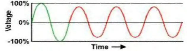
[image:20.595.178.494.612.698.2]According to IEEE Std. (1995) whenever the voltage lags 10 to 20 percent from the nominal voltage for duration more than 60 seconds, it is defined as under voltage while voltage that exceed 10 to 20 percent of the nominal voltage for more than 60 seconds, it is defined as over voltage. Figure 2 and 3 shows under and over voltage waveform respectively.
6 Figure 2.1.1a: Over Voltage Waveform (Kapoor et al. 2014)
Both of these circumstances that operate outside the acceptable power envelop are shown at CBEMA Curve in Figure 2.1.1b.
Figure 2.1.1b: CBEMA Curve
(Source: http://www.hersheyenergy.com/voltage_irregularitires.html n.d.)
2.1.2 Causes of Over Voltage
7
2.1.2.1 External Over Voltage
Atmospheric disturbances notably lighting is the main cause of these over voltages. These over voltages take form of a unidirectional impulse whose the highest possible amplitude has no direct relationship with the operating voltage of the system (Ram & Vishwakarma, 2011, pg592).
There are several factors that create the external voltages. (a) Direct lightning strokes.
(b) Lightning discharge that occur close to the line will electromagnetically induced over voltage (usually known as side stroke).
(c) Atmospheric condition that evolving along the line length will induced voltages.
(d) Charged cloud which presence nearby will electrostatically induced over voltages.
8 Figure 2.1.2.1 to 2.1.2.1b shows factors that creates external over voltage.
Figure 2.1.2.1: Over Voltage due to Direct Lightning Stroke
(Source: http://electrical-engineering-portal.com/overvoltages-caused-by-lightning 26/04/13)
Figure 2.1.2.1a: Over Voltage due to Lightning Discharge that Occur Close to the Line
(Source: http://electrical-engineering-portal.com/overvoltages-caused-by-lightning 26/04/13)
Figure 2.1.2.1b: Over Voltage due to Presence of Charged Cloud (Source:
9
2.1.2.2 Causes of Over Voltage: Internal Over Voltage
These over voltage are created by changes in the working conditions of the electrical system. According to Ram & Vishwakarma (2011) these internal over voltages are caused by either switching over voltages (transient over voltages of high frequency) or temporary over voltages (steady state over voltages of power frequency).
Transient over voltages happen when there is changed of network state by a switching operation or fault condition. They are generally oscillatory and in the form of damped sinusoid. Their frequencies may differ between several hundred Hz to several kHz and it is control by the immanent inductances and capacitance in the circuit. As an example, switching on or off equipment like switching a high rectors and a transformer while no load connected will render over voltages of transient nature.