DEVELOPMENT OF CUTTING TECHNOLOGY FOR
CUTTING POLYMER FOAM MATERIAL
MUHAMAD SHAFIQ BIN CHE ROIZIMI
B051310016
UNIVERSITI TEKNIKAL MALAYSIA MELAKA
UNIVERSITI TEKNIKAL MALAYSIA MELAKA
DEVELOPMENT OF CUTTING TECHNOLOGY FOR CUTTING
POLYMER FOAM MATERIAL
This report submitted in accordance with requirement of the Universiti Teknikal Malaysia Melaka (UTeM) for the Bachelor Degree of Manufacturing Engineering
(Manufacturing Process) (Hons.)
by
MUHAMAD SHAFIQ BIN CHE ROIZIMI
B051310016
920408-03-5875
FACULTY OF MANUFACTURING ENGINEERING
Alamat Tetap:
NO. 604,
Kg Pdg Sakar Salor,
15100 Kota Bharu, Kelantan
Tarikh: ________________________
UNIVERSITI TEKNIKAL MALAYSIA MELAKA
BORANG PENGESAHAN STATUS LAPORAN PROJEK SARJANA MUDA
TAJUK: Development of Cutting Technology for Cutting Polymer Foam Material
SESI PENGAJIAN: 2015/2016 Semester 2
Saya MUHAMAD SHAFIQ BIN CHE ROIZIMI
mengaku membenarkan Laporan PSM ini disimpan di Perpustakaan Universiti Teknikal Malaysia Melaka (UTeM) dengan syarat-syarat kegunaan seperti berikut:
1. Laporan PSM adalah hak milik Universiti Teknikal Malaysia Melaka dan penulis. 2. Perpustakaan Universiti Teknikal Malaysia Melaka dibenarkan membuat salinan
untuk tujuan pengajian sahaja dengan izin penulis.
3. Perpustakaan dibenarkan membuat salinan laporan PSM ini sebagai bahan pertukaran antara institusi pengajian tinggi.
4. **Sila tandakan ( )
SULIT
TERHAD
TIDAK TERHAD
(Mengandungi maklumat yang berdarjah keselamatan atau kepentingan Malaysia sebagaimana yang termaktub dalam AKTA RAHSIA RASMI 1972)
(Mengandungi maklumat TERHAD yang telah ditentukan oleh organisasi/badan di mana penyelidikan dijalankan)
Disahkan oleh:
Cop Rasmi:
Tarikh: _______________________
DECLARATION
I hereby, declared this report entitled “Development of Cutting Technology for Cutting Polymer Foam Material” is the results of my own research except as cited in references.
APPROVAL
This report is submitted to the Faculty of Manufacturing Engineering of UTeM as a partial fulfillment of the requirements for the degree of Bachelor of Manufacturing Engineering (Manufacturing Process) (Hons.). The member of the supervisory is as follow:
i
ABSTRAK
Projek ini memberi tumpuan untuk membangunkan teknologi dalam bentuk mesin gergaji menegak untuk pembuatan polymer foam. Fungsi utama teknologi pemotongan adalah untuk mengurangkan saiz polymer foam seperti 2m (panjang) x 1m (tinggi) x 0.0254m (ketebalan). Pembangunan awal teknologi pemotongan dengan menyatakan masalah untuk mengurangkan ketebalan kerana tidak ada mesin yang sesuai untuk mengurangkan ketebalan polymer foam. Oleh itu, teknologi pemotongan telah dibangunkan dengan melibatkan beberapa kaedah kejuruteraan seperti reka bentuk, proses dan penilaian produk. Dari segi reka bentuk, proses yang terlibat adalah penentuan spesifikasi mesin, memilih dan menganalisis konsep reka bentuk berdasarkan Kaedah Pugh dan membangunkan lukisan sebenar berdasarkan konsep dan spesifikasi yang dipilih. Di samping itu, teknologi pemotongan telah dihasilkan dengan beberapa proses seperti pemesinan, memotong, kimpalan dan pemasangan. Setelah teknologi pemotongan keseluruhan selesai, ia telah dinilai berdasarkan keupayaan fungsi, prestasi belting dan
Finite Element Analysis (FEA). Untuk keupayaan fungsi, sistem menunjukkan prestasi
ii
ABSTRACT
iii
DEDICATION
To my beloved parents
iv
ACKNOWLEDGEMENT
First and foremost, I would like to express my highest appreciation to my supportive academic supervisor, Dr. Mohd Hadzley B. Abu Bakar. His supervision and support that gave me truly helps during the period of conducting my thesis. His never-ending supply of valuable advice and guidance has enlightens me and deeply engraved in my mind.
Next, I would like to dedicate my thankfulness to machinery laboratory technicians, who has been so warmth and kind to provide sincere assistance and good cooperation during the training period. Their co-operation is much indeed appreciated. In addition, I would like to thanks to FKP lecturers, for their assistance, which really spends their time to teach me a lots of knowledge regarding to the design development.
v
TABLE OF CONTENT
Abstrak i
Abstract ii
Dedication iii
Acknowledgement iv
Table of Content v
List of Tables ix
List of Figures x
List Abbreviations, Symbols and Nomenclatures xiv
CHAPTER 1: INTRODUCTION 1
1.1 Background of Project 1
1.2 Problems Statement 3
1.3 Objective 4
1.4 Scope of Project 5
CHAPTER 2: LITERATURE REVIEW 6
2.1. Existing Product 6
2.2. Components of Vertical Bandsaw Machine 6
2.2.1.Gear System 6
2.2.1.1. Helical Gear 7
2.2.1.2. Spur Gear 8
2.2.1.3. Straight Bevel Gear 10
2.2.1.4. Worm Gear 11
2.2.1.5. Hypoid Gear 12
vi 2.2.2.1. Type of Belt Drive 14 2.2.2.2. V-Belt Drive 16 2.2.2.3. V-Belt Analysis 18 2.2.2.4. V-Belt Drive Design 19 2.2.2.5. Belt Tension 21
2.2.3. Bearing System 22
2.2.3.1. Rolling Contact Bearing 22 2.2.3.2. Thrust Bearing 24 2.2.3.3. Mounted Bearing 26
2.2.4. Shaft 27
2.2.5. Electric Motor 28
2.2.5.1. Type of Motor 28
2.2.5.2. Motor Selection Factor 29
2.2.5.3. Motor Size 30
2.2.5.4. Basic Information of AC Motor 30 2.2.5.5. AC Motor Performance 31 2.2.5.6. AC Motor Frame Types 32 2.2.5.7. Induction Motor 35
2.2.6. Band Saw Blade 37
2.2.6.1. Blade Selection 39
2.2.7. Pulley System 43
2.2.8. Finite Element Analysis (FEA) 45 2.2.8.1. Von Mises Stress Failure 46 2.2.9. Manufacturing Process 47
2.2.9.1. Drilling 47
2.2.9.2. Sawing 48
vii
CHAPTER 3: METHODOLOGY 50
3.1. Introduction 50
3.2. Fabrication Process Flow 51
3.3. Overall Methodology 53
3.3.1.Design Concept 54
3.3.1.1. Conceptual Design of Vertical Bandsaw Machine 54
3.3.2.Design for Assembly 57
3.3.3.Selection Component and Process 57 3.3.4.Best Design Concept 57 3.3.5.Design for Manufacture 57
3.3.6.Prototype 58
3.3.7.Suggestion for Simplification of Product 58 3.3.8.Identification Process 58 3.3.9.Detail Design for Minimum Manufacturing Cost 58
3.3.10. Production 58
3.4. Pugh Method 59
3.4.1.Concept Selection 59
3.5. Component Selection for Vertical Bandsaw Machine 61
3.5.1.Gear (Spur Gear) 61
3.5.2.Belting System (V-Belt) 61 3.5.3.Bearing (Double Row, Deep Groove Ball Bearing) 62 3.5.4.Electric Motor (Induction Motor) 62 3.5.5.Bandsaw Blade (Spring Tooth Bandsaw Blade) 62 3.6. Manufacturing Process Selection 63
3.6.1.Sawing Process 63
3.6.2.Drilling Process 63
viii
CHAPTER 4: RESULT AND DISCUSSION 71
4.1. Development and Fabrication Process 71 4.1.1.The Fabrication of Vertical Band Saw Machine 71 4.1.2.Components Assembly of Vertical Bandsaw Machine 74 4.2. Analysis on Vertical Bandsaw Machine 80
4.2.1.Test Cutting 80
4.3. Analysis on Belting Performance 82
4.3.1.New Belt 82
4.3.2.Broken Belt 83
4.3.3.Worm Belt 85
4.4. Analysis of FEA Result 86
4.4.1.Upper Load 86
4.4.2.Side Load 93
CHAPTER 5: CONCLUSION AND RECOMANDATION 102
5.1. Conclusion 102
5.2. Recommendation 103
5.3. Sustainability 104
REFERENCE 105
ix
LIST OF TABLES
3.1 Pugh method table for Vertical Bandsaw Machine 60
3.2 Type of material for each components of Vertical Bandsaw Machine 66
x
LIST OF FIGURES
1.1 Polymer foam material 1
1.2 Commercial Vertical Bandsaw Machine 2 1.3 The possible failure of bandsaw blade 3 1.4 The possible failure belting that normally occurred 4
2.1 Gear System 7
2.2 Helical Gear 8
2.3 Automotive Gearboxes 8
2.4 Spur Gear 9
2.5 Spur Gear with Spoked 9
2.6 Straight Bevel Gear 10 2.7 Differential of an automobile 11 2.8 Worm and Worm Gear Set 12 2.9 Single-enveloping Worm Gear Set 12
2.10 Hypoid Gear 13
2.11 Belt Drive 14
2.12 Basic belt drive geometry 14 2.13 Example of belt construction 15 2.14 Cross section of V-belt and sheave groove 16 2.15 Basic belt drive geometry 17 2.16 Heavy-duty industrial V-belts 20 2.17 Industrial narrow-section V-belts 20 2.18 Light-duty, fractional horsepower (FHP) V-belts 20
2.19 Automotive V-belts 21
2.20 Belt tension 21
xi 2.22 Double Row, Deep Groove Ball Bearing 24 2.23 Spherical Roller Thrust Bearing 24 2.24 Cylindrical Roller Thrust Bearing 25 2.25 Tapered Roller Bearings 25 2.26 Ball Bearing Pillow Block 26
2.27 Shaft Bearing 27
2.28 Single phase AC power 31
2.29 Three phase AC power 31
2.30 General form of motor performance curve 32
2.31 Foot mounted 33
2.32 Cushion base 33
2.33 C-face mounting 34
2.34 Induction motor cross section 35 2.35 Induction motor lamination 36 2.36 Squirrel cage rotor without laminations 36
2.37 Spring and swage set 37
2.38 Tooth Swaging Phases 38
2.39 Spring Tooth Blade 38
2.40 Raker Tooth Setting 39
2.41 Pitch of Teeth 40
2.42 Selection of Blade Pitch 41 2.43 Bandsawing Radius Guide 41 2.44 Angular Blade Guide Attachment 43
2.45 Pulley System 44
2.46 Pulley Wheel 44
2.47 Pulley Wheel with Keyed Shaft 45 2.48 Example of FEA analysis 46 2.49 The six stress components in 3-D state 46
2.50 Drilling Process 48
xii
2.52 Mechanical Assembly 49
3.1 Flow Chart of Project Planning 51 3.2 Flowchart for Overall Methodology 53
3.3 Concept Design 1 54
3.4 Concept Design 2 55
3.5 Concept Design 3 56
3.6 The main components of the vertical bandsaw machine 65 3.7 The complete sketch of Vertical Bandsaw Machine 66 3.8 The applied material for FEA analysis 67 3.9 The fixed location of FEA analysis 67 3.10 Upper load direction 68 3.11 Side load direction 69 3.12 The applying mesh for structure of machine 70
4.1 Measuring process by using measuring tape 72 4.2 Cutting process of aluminum steel bar 72
4.3 The drilling process 73
4.4 The components of Vertical Bandsaw Machine 76 4.5 The assembly process of Vertical Bandsaw Machine 79 4.6 The polymer foam material is placed at the jig 80
4.7 Cutting process 81
4.8 Feeding direction curing the cutting process 81 4.9 The burr at surface of new belt 83 4.10 The burr at surface of broken belt 84 4.11 The burr at surface of worm belt 85 4.12 The result of FEA analysis based on the load simulation from upper load
direction 88
4.13 The maximum stress at the upper junction between upper frame and
xiii 4.14 The displacement result of FEA analysis based on the load simulation
from upper load direction 92 4.15 The maximum displacement at the top upper frame and at the corner
between aluminium steel bar 92 4.16 The Stress result of FEA analysis based on the load simulation from
side load direction 95
4.17 The maximum stress between the joining for the both frame and
aluminium steel bar 96
xiv
LIST OF ABBREVIATIONS, SYMBOLS AND
NOMENCLATURE
AC - Alternative Current C - Center Distance D - Diameter DC - Direct Current
FEA - Finite Element Analysis FHP - Fractional Horsepower Hz - Hertz
HP - Horse Power kW - Kilowatts L - Pitch Length Mm - Millimeter mhp - Milihorsepower N - Newton
NEMA - National Electrical Manufacturers Association Pa - Pascal
R - Radius
tpi - Teeth per inch W - Watts
ω - Angular Velocity
1
1.1 Background of Project
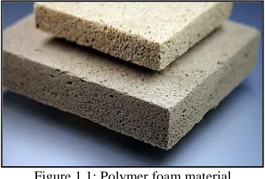
[image:22.612.234.420.563.689.2]Polymer foam is made up from solid and gas phase mixed together to form a foam. The polymer foam is found virtually everywhere in modem world and are used in a wide of application such as producing automotive components, aerospace part, construction material, the cushioning furniture, toys, games, packaging and decoration. Most of the polymer foam prepared with the size around 1m (length) x 2m (high) 0.0254m (thickness). Certain this polymer foam thickness need to reduce for specific propose. In this manner, the vertical band saw machine is the most suitable machine to cut the thickness of polymer foam with the minimum expense required. Figure 1.1 shows the example of polymer foam material.
Figure 1.1: Polymer foam material (Source: Okolieocha et al,2015)
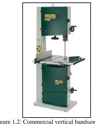
2 The bandsaw machine is the machine that produces continuous cutting process with teeth along one edge to cut many types of workpiece. The band saw blade is underpinned and determined by a drive wheel and an idler wheel. The bandsaw machines are divided into two classifications which are horizontal and vertical machines. On vertical machines, the position of cutting edge is vertical and cut into the side of the workpiece. The blade is rotated on the fixed track between the idler wheel mounted over the worktable while the drive wheel mounted underneath the worktable. The workpiece is moved by manually against the blade to make the cut.
[image:23.612.235.390.460.662.2]Two major components that controlled the performance of bandsaw in blade and belting. The function of blade is to cut the material according to the shape and precision required. There are many blades available for the bandsaw, consisted of high speed steel and coated high speed steel. The performance of the blade depended on the wear resistance of the tooth of blade. On the other hand, the belting of the bandsaw control the movement of the blade according to the ratio of motor belting rotation. The belting normally made from leather, available of various size according to the motor. Performance of belting influence by the strength of tooth that engage with the pulley form motor. Low performance of belting will reduce the durability of bandsaw. Figure 1.2 shows example of commercial vertical bandsaw machine.
3
1.2 Problems Statement
The polymer foam with the size 2m (length) x 1m (high) x 0.0254m (thickness) is supplied by the DK composite company. The material is used as the damper for the body aerospace part and for other thickness components. So, one machine must be produced to cut this thickness of material from 0.0254 m to 0.02 m and the machine that provide this process is Vertical Bandsaw. This type of machine does not exist at any industrial and it must be done by custom made. Commercial Vertical Bandsaw Machine is too small and it's not suitable to cut this thickness of material. Bandsaw blade in the market also small and the space between the blade guides for cutting is too short. Usually the operator load the workpiece through the cutting blade by manual using their hands and it very difficult to load a bigger size of workpiece.
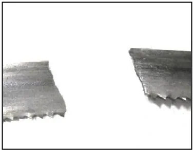
[image:24.612.233.421.488.634.2]On the other hand, there are no analysis of belting performance the available bandsaw. Normally failure will occur when one of the belting tooth distort. Such situation affected the bandsaw process as the cutting process will be interfered when the belting damaged. Figure 1.3 and Figure 1.4 shows the possible failure of bandsaw blade and belting that normally occurred. This project will fabricate a new bandsaw for polymer foam cutting, evaluate the function ability of machine in term of belting performance and demonstrate the structure performance of the machine by applying FEA analysis.