This is a repository copy of
Development of a vision system for TIG welding - a
work-in-progress study
.
White Rose Research Online URL for this paper:
http://eprints.whiterose.ac.uk/133358/
Version: Accepted Version
Proceedings Paper:
French, R., Yeadon, W., Kapellmann, G. et al. (1 more author) (2018) Development of a
vision system for TIG welding - a work-in-progress study. In: 2018 IEEE 23rd International
Conference on Emerging Technologies and Factory Automation (ETFA). IEEE 23rd
International Conference on Emerging Technologies and Factory Automation (ETFA 2018),
04-07 Sep 2018, Turin, Italy. IEEE , pp. 1193-1196. ISBN 978-1-5386-7108-5
https://doi.org/10.1109/ETFA.2018.8502461
© 2018 IEEE. Personal use of this material is permitted. Permission from IEEE must be
obtained for all other users, including reprinting/ republishing this material for advertising or
promotional purposes, creating new collective works for resale or redistribution to servers
or lists, or reuse of any copyrighted components of this work in other works. Reproduced
in accordance with the publisher's self-archiving policy.
[email protected] https://eprints.whiterose.ac.uk/
Reuse
Items deposited in White Rose Research Online are protected by copyright, with all rights reserved unless indicated otherwise. They may be downloaded and/or printed for private study, or other acts as permitted by national copyright laws. The publisher or other rights holders may allow further reproduction and re-use of the full text version. This is indicated by the licence information on the White Rose Research Online record for the item.
Takedown
If you consider content in White Rose Research Online to be in breach of UK law, please notify us by
Development of a Vision System for TIG Welding
-A Work-in-Progress Study
R. French
Physics & Astronomy The University of Sheffield
Sheffield, UK [email protected]
W. Yeadon
Physics & Astronomy The University of Sheffield
Sheffield, UK [email protected]
G. Kapellmann
Physics & Astronomy The University of Sheffield
Sheffield, UK
H. Marin-Reyes
Physics & Astronomy The University of Sheffield
Sheffield, UK
Abstract—The development of a Vision System for TIG Weld-ing has the potential to help realize a real time process monitorWeld-ing system for joining tasks which require automated welding. A key application of this technique is in the Nuclear Industry; where industrial components require several passes (layers of welding) to achieve robust joints. Through monitoring a welding process such as this in real time, material and time waste could be drastically reduced as faults could be instantly identified.
A TIG welding arc is a very intense source of both light and heat, making the creation of a vision system for it challenging. Higher currents result in; brighter TIG welding arcs, higher energy input and deeper and wider weld pools. Nuclear industry applications require deep penetration welding but bright TIG welding arcs can overwhelm the intensity of an auxiliary illumi-nation laser reducing the image clarity of an observing camera system. Thus, a balance between a wide weld bead with clear features applicable to deep penetration but without a brightness level which overwhelms that of the laser must be found.
This paper is a Work-in-Progress study of a vision system for TIG welding using an automated TIG welding system and a camera with a laser illumination system. Welding was performed using a Miller Dynasty 350 at 100A with a 3B class laser used to illuminate the weld pool.
Index Terms—Machine Vision, TIG Welding, Process Moni-toring
I. INTRODUCTION
Intelligent welding machines that can imitate human skills are still not a reality. But with new and improved measuring techniques, more accurate technology provides better quality automated welding machines. One interesting challenge is the measuring and visualization of the weld pool in real time. Mainly, the brightness of the arc does not allow a normal camera to capture any detail of the weld pool.
In every welding process, the generated weld pool contains relevant information regarding the ongoing welding process. For example, its geometry, shape and fluid dynamics can provide valuable information to modify the control parameters of an automatic welding machine. For arc welding, the arc geometry and behaviour can also contribute to these set of parameters. But measuring the arc and/or weld pool during TIG welding is not an easy task, specifically because of the high temperatures that the different materials need to reach to melt and also because of the level of brightness from the arc. Visual sensing can be effective as it is totally non-invasive. But for it to work, the excess of generated light from the
arc needs to be properly filtered and eliminated. Real time visual information will enable an instant reaction to weld pool mistakes or welding errors. This is especially important when welding takes a significant amount of time as real time identification of faults will allow for a process to be stopped and a mistake rectified compared to post hoc identification resulting in material and time waste.
II. RELATEDWORK
Some previous works have explored different techniques to measure different aspects of welding. For arc welding, the first attempt to observe the weld pool in real time was based on eliminating the brightness of the arc and using a pulsed laser synchronized with a camera [1]. In it, the pulsed laser was used only as a synchronous illumination source. The combination of a laser in a wavelength of an area of low intensity in the arc spectrum and a filtered camera has been further developed to improve image quality [2].
TIG Arcs produces a wide varying spectrum of high inten-sity light however for Laser Beam Welding (LBW), auxiliary light sources have successfully been eliminated in vision systems [3]. This is because the laser beams used for the welding in LBW can also be incorporated as the illumination for the camera system. Yet this has not made auxiliary illu-mination sources obsolete in LBW as their use has allowed for vision-based weld pool boundary extraction and width measurement [4] which is important for ensuring a common standard of quality in industrial welding situations. In addition to this, auxiliary light illumination has been incorporated in techniques for fluid flow observation in LBW [5]. Observation of the weld pool surface during LBW have been used to understand keyhole weld pool dynamics [6], observing and interpreting the surface of weld pools is a significant part of mimicking a human welder [7] and thus is important in automated welding systems.
A. Weld Pool Dynamics
Through the development of a vision system, specific weld pool effects have the potential to be identified. Thus, critically, an advanced vision system has the potential to become an extra ’eye’ in a verification of a computational model of a weld. An experimentally verified computational model may be able to accurately predict weld quality before any investments are made on physical apparatus thus reducing R&D costs.
The dominant forces in welding pool dynamics depend on the welding process. Specifically for Tungsten Inert Gas (TIG) welding, the dominant forces are The Marangoni Effect, The Lorentz Force and Arc Pressure. Arc Pressure is caused by the momentum transfer from the impinging electric arc onto the weld pool. The Lorentz force in an artifact of the electromagnetic fields within the welding arc and The Marangoni Effect is cause by the change of the surface tension of the weld pool with temperature and the subsequent surface tension gradient created on the weld pool surface.
[image:3.612.317.558.284.444.2]III. EXPERIMENTALSETUP
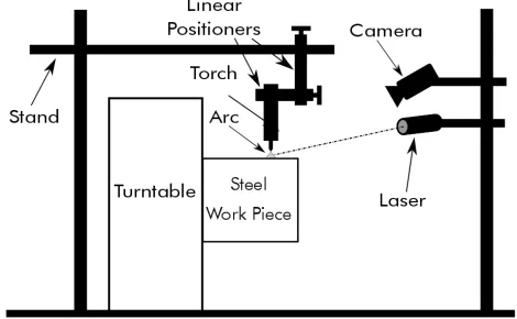
Figure 1 presents a diagram of the experimental setup. A USB camera, a 3B class laser and beam expander were positioned on a stand and targeted at an automated welding system. All of these components were secured on the same side of the set-up.
Fig. 1: Schematic of the experimental setup; a system of stands and linear positioners hold a weld torch above a cylindrical piece of steel pipe attached to a turntable. During welding, the steel pipe is rotated by the turntable. Note the camera and laser are positioned on the same side of the work piece, secured onto an independent stand.
A. Automated Welding System Setup
An automated TIG welding technique was used for the ex-periment. TIG welding is a fusion welding technique involving the generation of an electric arc between the TIG torch (torch) and the metal which is to be welded (work). The arc is shielded by an inert gas (usually argon or helium) creating an inert atmosphere for welding and removing impurities in the air and metal surface. For this study we used pure argon as firstly
it is the most cost effective choice and secondly it is the most popular choice when welding steel. The welding machine used was a commercial model Miller Dynasty 350 (Miller) set to 100 Amps.
The test pieces were cylinders of 316 stainless steel with 22 inch OD and 0.5 inch wall thickness . Figure 1 shows how the work piece was manipulated using a automated turntable with the torch held stationary via a system of linear positioners secured on a stand. The arc gap was fixed at3 mmfor all the welding tests.
B. Bandwidth Selection
[image:3.612.56.291.374.519.2]A set of readings were taken with an spectrometer to measure the spectrum of the welding arc. One of the lowest components of the spectrum was located around405 nm. For this reason, we decided to use a 405 nm laser to illuminate the welding area. Figure 2 shows a comparison between the measured spectrum of the arc against the measured spectrum of the laser.
Fig. 2: Comparison between the arc spectrum from the Miller welding machine and the laser. The laser spectrum is shown in black and is focused around 405 nm, the arc spectrum is shown in yellow. A resonance peak of the laser can also be seen focussed around810 nm.
C. Vision Hardware Setup
We used a black & white Imaging DMK U23K445 camera with a Computar Macro 10X amplification lens. In front of it, a405 nmband-pass filter (Thorlabs FB405-10) was installed. This filter allowed us to reject all the light except of that within the 405 nm±2 nm region. For this same reason, we used a 405 nm laser of 500W. The power of the laser was enough
to allow us to illuminate more area than just a spot, so we decided to expand the beam by a factor of XX. The expanded beam then was pointed between the electric arc and the formed welding bead to act as external illumination source for the camera.
D. Vision Software Setup
saturation and acquisition time of the camera. With it, we were able to save a set of images from every captured frame or record a video. Figure 3 shows the layout of the GUI designed for the capturing of the different video streams.
Fig. 3: Screen capture of the software GUI used for capturing the video streams. The upper panel shows a histogram of the current image. The lower two panels show the live video stream. Currently, both of the lower panels are identical but this will be changed in future work.
IV. CURRENTRESULTS
The principle goal of this vision system is to identify fea-tures of the weld in real time while avoiding the overwhelming brightness of the welding arc. Observing the raw video feed from the camera, the features of the weld pool can be easily identified especially if the observer is familiar with the TIG welding technique. Figure 4 shows an example image captured from one of the recorded videos of a moving weld. The image was taken approximately half way through the weld pass which was moving at35.9 cm/minand was5.76 cmlong. Here, the arc is at its peak brightness and the weld pool appears to be stable.
(a) Raw Image (b) Features Highlighted
Fig. 4: Images of the welding process taken with a welding current of 100A. 4a) Presents the raw image captured by the vision system. 4b) Presents the same image with the weld bead highlighted with a dashed white line.
A. Weld Pool Formation
[image:4.612.317.559.157.385.2]The understanding of the formation of the weld pool has been key in the development of advanced welding technologies such as K-TIG and PKAW. Figure 5 demonstrates how this vision system has a high enough frame rate to be capable of identifying the initial upslope of the arc (the increase in welding current once the arc has struck) and the formation of the weld pool.
Fig. 5: Images showing the upslope of the arc and the formation of the weld pool. The images are numbered to illustrate time progression from from first (1.) to last (4.)
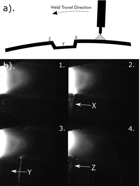
B. Welding over a Notch
To elucidate the potential of this work-in-progress system, welding was performed on both a reasonably smooth surface and then a surface with an artificial notch approximately1 mm deep. The notch was purposely machined onto the cylindrical steel work piece as a test method of the efficacy of the vision system.
A schematic of the notch welding process in shown in figure 6a) with 6b) showing a selection of images taken during the process. The images show key features that are easily identifiable to a human observer familiar with arc welding and, due to the image clarity, may also be identifiable to a computational image processing system. These key features are the noticeable fluctuations in arc shape as the distance between the electrode and work piece (the arc gap) is increased and distinguishable beginning and end of the notch as the light from the arc and the laser reflects off of it.
[image:4.612.48.299.530.649.2]Fig. 6: a) Schematic showing the direction of welding over the introduced notch. b) Select images showing the welding over the notch with the images numbered from first (1.) to last (4.) to show time progression. Points X,Y and Z show how images a) and b) relate, note how the edges of the notch can be identified using the vision system.
Fig. 7: Picture of one of the introduced notches Post-Welding.
V. CONCLUSIONS
A welding vision system has been developed for process monitoring. As evidenced from the results section, weld seam
features can be identified with this experimental set up. The combination of the light from the laser and the light from the arc allows for good illumination of the weld seam and a clearly distinguishable arc plasma. However, there is still room for optimization of the vision system to improve the images produced.
There is considerable potential for further expansion of the process monitoring set-up by including additional measuring apparatus. For instance, current and voltage measurements could be integrated with the vision system to allow for measurements ’inside’ the weld pool as well as the visual look of the ’outside’ of it. Current and voltage measurements could allow for an integrated system whereby deviations outside of expected values for current and voltages - indicative of a poor quality weld - would be able to ’tag’ images recorded by the vision system to be analyzed.
Overall, the combination of the laser and camera system creates a vision system with sufficient clarity to be used in computer vision systems and to use algorithms for real time processing.
VI. FUTURE WORK
Potential future work includes the identification and pro-cessing of the video stream computationally. This would work well with a the system which can control a reaction to possible errors in real time. Initially this may be simply stopping a multiple pass weld once a crack or damage is identified but this would be the basis for a future system where poor welds could be automatically corrected before they become large issues. Applying machine learning techniques to error detection may enhance this capability.
ACKNOWLEDGMENT
We are very grateful to Industrial 3D Robotics, especially Dr. Benjamin Crutchley for their invaluable support.
REFERENCES
[1] R. Kovacevic and Y. Zhang, “Real-time image processing for monitoring of free weld pool surface,” Journal of Manufacturing Science and Engineering, vol. 119, no. 2, pp. 161–169, 1997.
[2] B. Abdullah, J. Smith, W. Lucas, J. Lucas, and F. Malek, “Monitoring of tig welding using laser and diode illumination sources: A comparison study,” inElectronic Design, 2008. ICED 2008. International Conference on. IEEE, 2008, pp. 1–4.
[3] S. Lee and S. Na, “A study on automatic seam tracking in pulsed laser edge welding by using a vision sensor without an auxiliary light source,” Journal of Manufacturing Systems, vol. 21, no. 4, p. 302, 2002. [4] M. Luo and Y. C. Shin, “Vision-based weld pool boundary extraction
and width measurement during keyhole fiber laser welding,”Optics and Lasers in Engineering, vol. 64, pp. 59–70, 2015.
[5] I. Eriksson, P. Gren, J. Powell, and A. F. Kaplan, “New high-speed photography technique for observation of fluid flow in laser welding,” Optical Engineering, vol. 49, no. 10, p. 100503, 2010.
[6] A. Matsunawa, J.-D. Kim, N. Seto, M. Mizutani, and S. Katayama, “Dynamics of keyhole and molten pool in laser welding,” Journal of laser applications, vol. 10, no. 6, pp. 247–254, 1998.
[image:5.612.55.296.459.638.2]