flux reluctance machines
.
White Rose Research Online URL for this paper:
http://eprints.whiterose.ac.uk/139348/
Version: Accepted Version
Article:
Huang, L.R., Feng, J.H., Guo, S.Y. et al. (3 more authors) (2018) Rotor shaping method for
torque ripple mitigation in variable flux reluctance machines. IEEE Transactions on Energy
Conversion, 33 (3). pp. 1579-1589. ISSN 0885-8969
https://doi.org/10.1109/TEC.2018.2829493
© 2018 IEEE. Personal use of this material is permitted. Permission from IEEE must be
obtained for all other users, including reprinting/ republishing this material for advertising or
promotional purposes, creating new collective works for resale or redistribution to servers
or lists, or reuse of any copyrighted components of this work in other works. Reproduced
in accordance with the publisher's self-archiving policy.
http://www.ieee.org/publications_standards/publications/rights/rights_policies.html
[email protected] https://eprints.whiterose.ac.uk/ Reuse
Items deposited in White Rose Research Online are protected by copyright, with all rights reserved unless indicated otherwise. They may be downloaded and/or printed for private study, or other acts as permitted by national copyright laws. The publisher or other rights holders may allow further reproduction and re-use of the full text version. This is indicated by the licence information on the White Rose Research Online record for the item.
Takedown
If you consider content in White Rose Research Online to be in breach of UK law, please notify us by
Abstract—In this paper, four rotor shaping methods, i.e., eccentric circular, inverse cosine, inverse cosine with 3rd harmonic and multi-step shaping methods, are developed and compared for torque ripple mitigation in variable flux reluctance machines (VFRMs). By using a 6-stator-pole/7-rotor-pole (6/7) VFRM as an example, the design criterions and capabilities of these four methods are illustrated. It is found that all the rotor shaping methods are capable of torque ripple mitigation and applicable to all the VFRMs except those with 6k/(6i±2)k (k, i=1,2,3…) stator/rotor pole combinations. Moreover, the inverse cosine with 3rd harmonic and multi-step shaping methods are found to have the best performance. They are able to reduce the torque ripple by 90% at a cost of only 3% torque density reduction. A 6/7 VFRM with both conventional and shaped rotors is prototyped and tested for verification.
Index Terms—Average torque, rotor shaping, torque ripple, variable flux reluctance machine
NOMENCLATURE
rk k-th component of rotor radial permeance.
Ra Radius of the shaping arc in eccentruc circular
shaping method.
Rro Rotor outer radius.
Do Offset distance of the shaping arc in eccentruc
circular shaping method. Mechanical airgap length.
k Mechanical airgap length at the k
th
point for multi-step shaping method.
k Mechanical angle at the kth point for multi-step
shaping method.
Rrk Rotor radius at the k
th
point for multi-step shaping method.
g0 Minimum airgap length.
a, b, c Coefficients for inverse cosine and inverse cosine with 3rd harmonic shaping curves.
p Rotor pole pitch.
r Rotor pole arc
Rsi Stator inner radius
Idc DC current for field winding
L.R. Huang and Z.Q. Zhu are with the Electrical Machines and Drives Group, University of Sheffield, Sheffield S1 3JD, U.K. (e-mail: [email protected]; z.q.zhu@sheffield. ac.uk).
J.H. Feng, S.Y. Guo, Y.F. Li, and J.X. Shi are with the CRRC Zhuzhou Institute Co. Ltd, Shidai Road, Shifeng District, Zhuzhou, Hunan, China (e-mail: [email protected]; [email protected]; [email protected]; [email protected];).
(a) (b)
(c) (d)
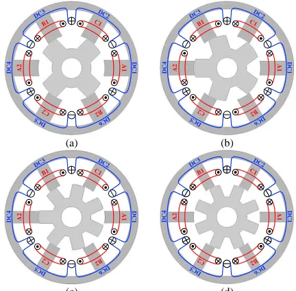
Fig. 1. Cross sections of the VFRMs with different stator/rotor pole combinations. (a) 6s/4r. (b) 6s/5r. (c) 6s/7r. (d) 6s/8r.
I. INTRODUCTION
ARIABLE flux reluctance machines (VFRMs) were developed as a type of stator-wound-field (SWF) magnetless electrical machines [1][2]. The configurations of four typical VFRMs, i.e., 6-stator-pole/4-rotor-pole (6/4), 6/5, 6/7, 6/8 VFRMs, are presented in Fig. 1. They have doubly-salient core structures, which are similar to those of switch reluctance machines (SRMs) [3][4] and vernier reluctance machines (VRMs) [5][6]. However, the two sets of stator-located concentrated windings, i.e., AC-excited armature winding and DC-excited field winding, distinguish the VFRMs from the SRMs and the VRMs, where only one set of excitation exists. In fact, the topology of VFRMs could originate from either dual-winding reluctance machine [7], SRM or VRM, yielding different names, i.e., multi-pole synchronous machine [1], VFRM [2], DC winding excited VRM [8]. They are actually the same machine due to their common operating principle and are generally denoted as VFRMs in this paper.
Compared with conventional SRMs, VFRMs share their compact core and winding structure, but exhibit significantly lower torque ripple, vibration and acoustic noise [9]. The electromagnetic performance of VFRMs is comprehensively investigated in [10]-[12]. In [13], the torque production mechanism of VFRMs is illustrated by magnetic gearing effect. Based on this theory, the torque characteristics of VFRMs with different stator/rotor pole combinations are investigated in [14].
A
1
A
2
B1
B2 C1
C2
D
C1
DC2
DC3
D
C4
DC
5 6 DC
A
1
A
2
B1
B2 C1
C2
DC
1
DC2
DC3
DC4
DC
5 6 DC
A
1
A
2
B1
B2 C1
C2
D
C1
DC2
DC3
D
C
4
DC5 6 DC
A
1
A
2
B1
B2 C1
C2
D
C1
DC 2
DC3
D
C4
DC
5 6 DC
Rotor Shaping Method for Torque Ripple
Mitigation in Variable Flux Reluctance Machines
L.R. Huang, J.H. Feng, S.Y. Guo, Y.F. Li, J.X. Shi, and Z.Q. Zhu, Fellow, IEEE
[image:2.612.331.547.176.388.2]With the purpose of boosting the torque quality of VFRMs for high performance applications, both the control and machine design techniques can be applied. In [15] and [16], an open-winding and a dual three-phase control method are proposed to successfully enhance the torque density of VFRM. In this paper, the potential utilization of rotor shaping methods for torque ripple mitigation in VFRMs is investigated. In fact, the rotor pole shaping methods, including the eccentric circular, inverse cosine and inverse cosine with 3rd harmonic shaping methods have already been widely used in rotor-wound-field, interior permanent magnet (IPM), surface mounted permanent magnet (SPM) synchronous machines to generate sinusoidal distributed airgap field and enhance electromagnetic performance [17]-[19]. In contrast, there are few existing pole shaping methods documented for machines with doubly-salient structures. Several attempts have been made to reduce the torque ripple in SRM by using relative eccentricity of the stator and rotor poles [20], rotor flux barriers [21], rotor notches [22], slant stator pole face [23][24], skewed rotor poles [25]. All of these methods make the pole shapes geometrically asymmetric and are specific for the torque profiles of SRMs, which makes them difficult for application in VFRMs. In [26], the eccentric circular rotor shaping method is employed in the DC-excited flux switching motor (SFM). This attempt is found to be successful in torque ripple mitigation, albeit with an inevitable reduction in average torque. This paper further presents a possible way to apply the inverse cosine, inverse cosine with 3rd harmonic and multi-step shaping methods to the VFRMs with redesigned shaping curves, which are different from those used in conventional synchronous machines.
The paper is organized as follows. In Section II, the relationship between average torque, torque ripple and rotor permeance harmonics is illustrated. In Section III, the design criteria of four rotor shaping methods are introduced. Then, in Section IV, by using the 6/7 VFRM as an example, the electromagnetic performance of different shaping methods are evaluated and compared. Further, the feasible stator/rotor pole combinations for rotor shaping methods are identified in Section V. Finally, a 6/7 VFRM with both conventional and shaped rotors is prototyped for experimental validation.
II. TORQUE CHARACTERISTICS OF VFRMS
By using magnetic gearing effect and harmonic analysis, the relationship between average torque, torque ripple and rotor permeance harmonics in VFRMs with different stator/rotor pole combination are identified in [7] and [8], and presented in Fig. 2. The torque characteristics can be defined as:
(a) The average torque is proportional to the 1st rotor radial permeance harmonic for all the VFRMs.
(b) For VFRMs with 6k/(6i±2)k (k, i=1,2,3…) stator/rotor pole combinations, their torque ripples are mainly from the reluctance torque and proportional to the 1st rotor radial permeance harmonic, which leads to large torque ripple in these machines. In contrast, the torque ripple of other VFRMs are related to the 4th, 5th and 6th rotor radial permeance harmonics and relatively small.
For verification, four VFRMs (6/4, 6/5, 6/7 and 6/8) were
designed using the global optimization method under the same constraints of stator outer radius and copper loss to reach the maximal output torque and the lowest torque ripple. Their configurations, specifications and torque profiles are presented in Fig. 1, Table I, and Fig. 3, respectively. As expected, the 6/5 and 6/7 VFRMs exhibit significantly smaller torque ripple (8%-9%) than the 6/4 and 6/8 VFRMs (>50%), which makes them preferable choices for some applications. However, an 8-9% torque ripple is still large for some advanced motor drive systems, where a smooth output torque is required. Hence, the potential utilization of the rotor shaping method for torque ripple mitigation in VFRMs is investigated in this paper.
The basic theory is as follows. It is known that the rotor shaping method is capable of modifying the harmonic content of rotor permeance. For 6k/(6i±2)k VFRMs, their average torque and torque ripple are both proportional to the 1st rotor permeance component. Thus, the torque ripple can only be mitigated by reducing the magnitude of the 1st rotor permeance component. However, the average torque will also decrease simultaneously. In contrast, the torque ripples of other VFRMs are related to the 4th, 5th and 6th rotor permeance components, as marked by a red dashed line in Fig. 2. In this case, the rotor shaping method can be applied to these machines to suppress the higher order harmonics in rotor permeance and mitigate their torque ripple. Meanwhile, the 1st permeance component is expected to be kept as large as possible to retain the average torque.
Fig. 2. Torque characteristics of VFRMs.
TABLEI
SPECIFICATIONS OF GLOBALLY OPTIMIZED VFRMS
Parameter Unit 6s/4r 6s/5r 6s/7r 6s/8r
Stator outer radius mm 45
Airgap length mm 0.5
Rated total copper loss W 30
DC-bus voltage V 20
Turns per coil (AC/DC) - 144/144
Packing factor - 0.4
Stack length mm 25
Shaft diameter mm 14
Split ratio - 0.5 0.52 0.56 0.58 Stator inner radius mm 22.5 23.4 25.2 26.1 Stator pole arc deg. 27 24 18.6 16 Stator pole height mm 17.2 16.8 15.5 14.4
Rotor pole arc deg. 34.6 26 18.8 16 Rotor pole height mm 9.5 9.4 9.2 8.7 Average torque Nm 0.55 0.64 0.72 0.69
Torque ripple - 101% 9.1% 8.3% 59.2%
VFRMs
6k/(6i±2)k VFRMs Other stator/rotor pole combinations
Average torque Torque ripple Average torque Torque ripple
5
, ,
r r r
1 r
1 r
1
*r
Fig. 3. Torque profiles of VFRMs with different stator/rotor pole combinations (Copper loss=30W).
III. ROTOR SHAPING METHOD
In this section, four rotor shaping methods are introduced. Since the 6/7 VFRM is a typical VFRM which does not have a 6k/(6i±2)k stator/rotor pole combination, it was chosen as an example in the following investigation to clearly illustrate the features and capabilities of the developed methods.
A. Method I: eccentric circular shaping method
[image:4.612.315.565.55.221.2]As can be seen from Fig. 4, the rotor pole outline can be defined by a single arc with a given radius. The relationship between the rotor structural parameters is governed by:
Fig. 4. Eccentric circular shaping method.
0 1 a ro ro D R R R
(1)
where Ra is the radius of shaping arc; Rro is the rotor outer
radius; Do is the offset distance of the shaping arc.
In this case, the minimum airgap length g0 is maintained
while the airgap length varies with an eccentric circle.
B. Method II: inverse cosine shaping method
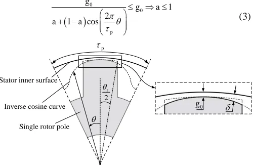
This method has been widely used in SPM and IPM synchronous machines. However, the electrical angle for one rotor pole is in synchronous machine but 2 in VFRMs. Hence, the equation of the shaping curve is modified into:
0 , , 2 2 2 1 cos r r p g a a (2)where g0 is the minimum airgap length; p is the rotor pole pitch;
a is a coefficient to be determined during design; and r is the
rotor pole arc.
The schematic of inverse cosine shaping method is shown in Fig. 5. In order to maintain the minimum airgap length in (2), a is governed by:
0 0 1 2 1 cos p g g aa a
(3)
Fig. 5. Inverse cosine shaping method.
C. Method III: inverse cosine with 3rd harmonic shaping method
The third method is reported in [12] and [13] to have enhanced torque density compared with the pure inverse cosine shaping method for SPM and IPM machines. The schematic of the inverse cosine with 3rd harmonic shaping for VFRM is shown in Fig. 6 and its shaping curve is governed by:
0 , , & 02 2 2 6 cos cos r r p p g c
a b c
(4)
where a, b and c are three coefficients to be determined. From (4), the minimum airgap length is obtained when:
12
2 3
0 cos
12
p
d c b
d c
(5)
And the minimum airgap length is:
0
min 3 1
2 2
1
3 3
3 g
a b c c
(6)
In order to maintain the minimum airgap length, the coefficients should satisfy:
0
min 3 1 0
2 2 2 1 3 3 1 3 3 3
3 1 , 1
g
g
a b c c
b a c c a
[image:4.612.48.301.331.485.2] (7)
Fig. 6. Inverse cosine with 3rd harmonic shaping method. D. Method IV: Multi-step shaping method
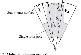
As shown in Fig. 7, the outline of the rotor pole is symmetrical and defined by several discrete points. The number of points can be chosen as any integer (6 points are
0 0.2 0.4 0.6 0.8 1
0 60 120 180 240 300 360
Tor
que
(
Nm
)
Rotor position (Elec. deg.)
6s/4r 6s/5r 6s/7r 6s/8r
ro R a R o D
Stator inner surface
Eccentric circle
Single rotor pole
0 g 2 r p
Inverse cosine curve Stator inner surface
Single rotor pole
0 g 2 r p
Stator inner surface
Inverse cosine with
3rd harmonic curve
Single rotor pole
0
[image:4.612.312.567.355.690.2]applied in this paper for example). Meanwhile, the adjacent points are connected by a straight line. The radius Rrk and
mechanical angle k of the k-th point are given by: 1
10
k r
k
(8)
0
,
rk si k k
R R g (9)
where Rsi is the radius of stator inner surface; k is the airgap
length at the kth point.
In order to obtain the optimal rotor pole shape, r and 1- 6
[image:5.612.57.230.176.293.2]are seven structural parameters to be optimized during design.
Fig. 7. Multi-step shaping method.
IV. ELECTROMAGNETIC PERFORMANCE EVALUATION
In this section, the electromagnetic performances of the proposed four rotor shaping methods are evaluated. For clarity, the original machine without rotor shaping is denoted as
“Original” in this section. The machines with the eccentric circular, inverse cosine, inverse cosine with 3rd harmonic and multi-step shaping methods are denoted as “Method I”,
“Method II”, “Method III”and “Method IV”, respectively. A. Global optimization method
Firstly, four 6/7 VFRMs with different shaped rotors are designed with the global optimization module of ANSYS Maxwell. For the sake of a fair comparison, their stators are identical to the original 6/7 VFRM shown in Table I and only the rotors are redesigned. The variables and constraints during the optimization are given in Table II.
Fig. 8 shows the optimization results of VFRM with rotor shaping method I. Each point represents the result of one specific set of structural parameters. Since the goal of the design is to minimize the torque ripple while maximizing the torque density, a Pareto front is added to each figure to indicate all of the optimal points which have the lowest torque ripple compared with other cases having the same average torque. Then, the knee point on the Pareto front, from which onwards the torque ripple starts increasing quickly, is chosen as the global optimal point. The same method can also be performed on the other three shaping methods. The detailed specifications of the four optimized rotors are listed in Table III and the cross sections of single rotor poles are shown in Fig. 9.
B. Rotor radial permeance
To investigate the performance of the different methods, the harmonic content of the rotor permeance is evaluated. By using the single-sided salience permeance calculation method developed in [13] and FEA, the radial permeance distribution and corresponding spectra of all the shaped rotors are obtained, as shown in Fig. 10. Compared with the conventional rotor,
some specific characteristics can be found:
(a) Although all of the fundamental permeance components of the shaped rotors are suppressed due to the increase in their equivalent airgap length, Method III and IV show much larger fundamental components than the other two methods, reaching 96% of the original one. According to the torque mechanism illustrated in Section II, the average torque of Method III and Method IV are expected to be much larger than those of Methods I and II, and only slightly smaller than the original motor.
(b) The magnitudes of ≥4th permeance harmonics are significantly suppressed using the rotor shaping methods. Hence, the torque ripples related to these components are expected to be mitigated as well.
TABLEII
CONSTRAINTS OF GLOBAL OPTIMIZATION FOR 6/7VFRMS WITH DIFFERENT SHAPING METHODS
Parameter Unit Rotor shaping method
I II III IV
Stator outer radius mm 45
Minimum airgap length mm 0.5
Stack length mm 25
Split ratio - 0.56
Stator pole arc deg. 18.6
Rotor pole arc ratio - 0.33 to 0.44
Rated total copper loss W 30
D0/Rr0 - 0 to 0.5 - - -
a - - -0.5 to 1 -0.5 to 1 -
c - - - 0 to 0.5 -
k mm - - - 0.5 to 2
TABLEIII
SPECIFICATIONS OF THE GLOBALLY OPTIMIZED ROTORS Parameter Unit Rotor shaping methods
I II III IV
Rotor pole arc ratio - 0.41 0.39 0.38 0.4
Rotor yoke thickness mm 9 9 8.8 8.8
D0/Rro - 0.49 - - -
A - - 0.25 0.295 -
C - - - 0.126 -
1, 2, 3, 4 mm - - - 0.5
5 mm - - - 0.56
6 mm - - - 0.8
Average torque Nm 0.637 0.643 0.70 0.70
Torque ripple - 2.8% 0.5% 0.9% 0.6%
Fig. 8. Global optimization results for VFRMs with eccentric circular shaping method.
k
2r
si
R
1 2 3 4 5
6 2 3 4 56
k
rk
R
Stator inner surface
Single rotor pole
0 0.5 1 1.5 2
0.64 0.642 0.644 0.646
T
o
rque
rippl
e
(%)
Average torque (Nm)
(a) (b) (c)
[image:6.612.51.296.48.246.2](d) (e)
Fig. 9. Single rotor poles of 6s/7r VFRMs with and without rotor shaping. (a) Original. (b) Method I. (c) Method II. (d) Method III. (e) Method IV.
(a)
[image:6.612.302.568.52.166.2] [image:6.612.323.557.195.477.2](b)
Fig. 10. Rotor radial permeance distributions of VFRMs with and without rotor shaping method. (a) Permeance distributions. (b) Spectra.
C. Flux linkage and magnetic field distributions
Then, the flux linkage and magnetic field of VFRMs with different rotor shaping methods are obtained. Since the rotor pole shape will affect the magnitude of the airgap field rather than the flux linkage pattern, the results of the original VFRM is presented in Fig. 11 as an example. Fig. 12 further compares the airgap magnetic fields of VFRMs with different rotor shaping methods. It can be seen that the airgap fields at the rotor tooth region are modified by different rotor pole shapes. Moreover, the amplitudes of all the harmonics are mitigated due to the reduction in airgap permeance when rotor shaping methods are used, which will help the reduction of iron loss in cores, as will be confirmed by the following investigations.
(a) (b)
Fig. 11. Flux linkage pattern and magnetic field distributions of original VFRM at initial position (copper loss is 30W). (a) Flux linkage distribution. (b) Field distribution.
(a)
(b)
Fig. 12. Airgap field distributions of VFRMs with different rotor shaping methods (copper loss is 30W). (a) Field distributions. (b) Spectra.
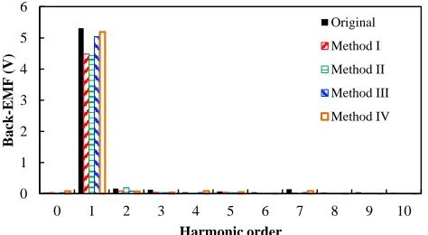
D. Back-EMF
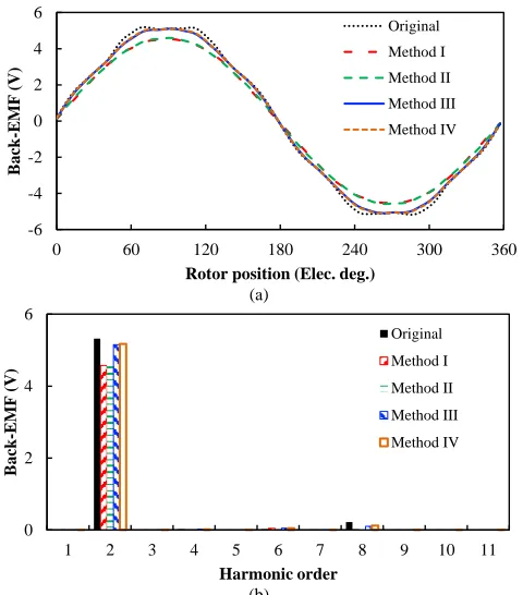
When the VFRMs operate in open-circuit mode and only the field winding is excited, the back-EMF can be calculated. Fig. 13 shows the waveforms and spectra of the back-EMFs. Meanwhile, the magnitudes of their fundamental components and THDs are compared in Table IV. It can be clearly seen that the shaped rotors can lead to more sinusoidal waveforms and significantly smaller THD in back-EMFs. However, the fundamental component of back-EMF will also witness a drop due to the reduction in rotor radial permeance. Specifically, Methods I and II have the most sinusoidal back-EMFs with the smallest THD. However, their fundamental components are only 86% of the original one. In contrast, Methods III and IV are able to maintain 97% of the fundamental back-EMF component of the original machine.
0 0.2 0.4 0.6 0.8 1 1.2
0 60 120 180 240 300 360
R
ot
or
perm
eance
(
p. u
.)
Electrical angle (deg.) Original
Method I
Method II Method III
Method IV
0 0.1 0.2 0.3 0.4 0.5 0.6
0 1 2 3 4 5 6 7 8 9 10
R
ot
or
radi
al
perm
eance
(
p.
u.)
Harmonic order
Original Method I
Method II Method III Method IV
0.2 0.4 0.6 0.8 1.0 1.2 1.4 1.6 1.8
0.0 2.0 B (T)
-2 -1 0 1 2
0 60 120 180 240 300 360
F
lux
densi
ty
(T
)
Mechanical position (deg.) Original
Method I Method II Method III Method IV
Rotor tooth regions
0 0.05 0.1 0.15 0.2 0.25 0.3
0 1 2 3 4 5 6 7 8 9 10
F
lux
densi
ty
(T
)
Harmonic order
Original Method I
Method II Method III
[image:6.612.55.293.279.550.2](a)
(b)
Fig. 13. Back-EMFs of 6s/7r VFRMs with and without rotor shaping (field current is 2A, rotating speed is 400rpm). (a) Waveforms. (b) Spectra.
TABLEIV
FUNDAMENTAL COMPONENT AND THD OF THE BECK-EMFS Parameter Unit Original Rotor shaping method
I II III IV
1st component
(Percentage) V
1.6
(100%)
1.37
(86%)
1.38
(86%)
1.54
(97%)
1.55
(97%)
THD - 4.3% 1.1% 0.7% 2.3% 2.6%
(a)
(b)
Fig. 14. Torque performances of VFRMs with and without rotor shaping method (copper loss is 30W). (a) Torque wavefroms. (b) Comparison of average torque and torque ripple.
E. Output torque
When the machines operate at rated condition, the output torques of the original and the redesigned VFRMs are calculated, as shown in Fig. 14. All of the shaping methods are shown to have the capabilities of mitigating torque ripple, albeit with a sacrifice in average torque. The performance can be concluded as:
(a) Methods III and IV are the best of the four methods, managing to reduce the torque ripple to only 8-10% of the original one, with 97% average torque maintained.
(b) Method II has the best performance in torque ripple mitigation, with only 6% torque ripple remaining. However, its average torque is also reduced to only 90% of the original.
(c) Method I is the weakest one among these four method, only managing to reduce the torque ripple to 34% of the original at a cost of 11% average torque.
F. Core losses and efficiency
Another advantage of the rotor shaping methods is the reduction in iron loss. Due to the switching of flux linkages in the rotor, the rotor iron loss of VFRM is much larger than that of the regular synchronous machines, which will degrade the efficiency of VFRMs. In the foregoing investigations, the rotor permeance harmonics, especially the high order ones, are proved to be suppressed with the rotor shaping methods, which is surely good for iron loss reduction.
By using the JMAG software package, the iron losses of the VFRMs with and without rotor shaping methods are calculated at 1000rpm, as presented in Table V. It can be seen that both the stator and rotor iron losses are reduced using the shaping methods. In comparison with the original, Methods I, II, III and IV present only 90%, 88%, 97% and 97% total core losses, respectively. However, considering the reduction in output power when rotor shaping methods are applied, the efficiencies of VFRMs with rotor shaping methods are slightly suppressed.
TABLEV
IRON LOSSES AND EFFICIENCIES FOR VFRMS WITH DIFFERENT ROTOR SHAPING METHODS AT 1000RPM
Parameters Original Rotor shaping method
I II III IV
Copper loss (W) 30
Stator iron loss (W) 2.6 2.4 2.3 2.5 2.5 Rotor iron loss (W) 1.7 1.5 1.5 1.7 1.7 Total core loss (W)
(Percentage)
4.3
(100%)
3.9
(90%)
3.8
(88%)
4.2
(97%)
4.2
(97%)
Output power (W)
(Percentage)
75.4
(100%)
66.7
(89%)
67.3
(90%)
73.3
(97%)
73.3
(97%) Efficiency
(Percentage)
0.69
(100%)
0.66
(96%)
0.67
(97%)
0.68
(99%)
0.68
(99%)
G. Vibration and acoustic noise
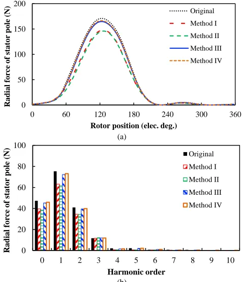
It is known that the rotor pole shape is closely related to the radial force distribution in electrical machines, which will eventually influence the vibration and acoustic noise in VFRMs. Fig. 15 compares the variations of average radial force of one stator tooth with rotor position in VFRMs with and without the rotor shaping method. It can be seen that the peak value of radial force and the harmonic amplitudes are reduced using the rotor shaping method.
Further, the acoustic noise and vibration of VFRMs with and
-6 -4 -2 0 2 4 6
0 60 120 180 240 300 360
B
ack
-E
MF
(
V
)
Rotor position (Elec. deg.) Original
Method I
Method II
Method III
Method IV
0 2 4 6
1 2 3 4 5 6 7 8 9 10 11
B
ack
-E
MF
(
V
)
Harmonic order
Original
Method I
Method II
Method III
Method IV
0.6 0.63 0.66 0.69 0.72 0.75 0.78
0 60 120 180 240 300 360
O
utput
torque
(N
m
)
Rotor position (Elec. deg.)
Original Method I Method II
Method III Method IV
0 0.2 0.4 0.6 0.8 1 1.2 1.4
Original Method I Method II Method III Method IV
P
er
uni
t
va
lue
Average torque Torque ripple
100%
89%
34% 90%
6% 97%
10% 8%
[image:7.612.54.294.48.321.2]without the rotor shaping method are also evaluated by a 3D model, created using the JMAG software package, as shown in Fig. 16. Both the machine and case are taken into account. The windings are treated as weights on the stator teeth. The natural frequency of VFRM can be calculated by eigenmode analysis and the vibration and noise response can be obtained by frequency analysis. Fig. 16(a) shows the 3D model of one kind of vibration mode 2 (8.9kHz) and Fig 16(b) shows the corresponding vibration distribution. Then, the acoustic noise responses of VFRMs with and without rotor shaping methods are obtained and compared in Fig. 17. It can be seen that all of the rotor shaping methods are able to reduce the acoustic noise of VFRMs. Specifically, Methods I and II manage to reduce the acoustic noise of the original motor by 5~9dB over the frequency range. Methods III and IV are able to reduce the acoustic noise by 2~3dB in the 0~10kHz region but have an even lower noise level than Methods I and II. Since the low frequency region is more critical to noise of electrical machines, Methods I and II are the best for noise reduction.
(a)
[image:8.612.313.550.52.175.2] [image:8.612.53.292.280.558.2](b)
Fig. 15. Variation of average torque radial force on one stator tooth with rotor position (copper loss is 30W). (a) Radial force. (b) Spectra.
(a) (b)
Fig. 16. Vibration mode 2 and corresponding vibration distribution for VFRM with original rotor (8.9kHz). (a) Vibration mode 2. (b) Vibration distribution.
Fig. 17. Noise level of VFRMs with and without rotor shaping methods.
V. STATOR/ROTOR POLE COMBINATION CONSIDERATION
In Section II, it was predicted that the rotor shaping method cannot be applied to 6k/(6i±2)k VFRMs. In this section, this conclusion is further verified by FEA.
Based on the global optimization method, the rotor shaping methods are also performed on 6/4, 6/5 and 6/8 VFRMs. The torque performance are presented in Table VI. It can be clearly seen that the rotor shaping methods work well in 6/5 VFRM for torque ripple mitigation while they have no effect in 6/4 and 6/8 VFRMs. This phenomenon confirms the conclusion that the proposed rotor shaping methods are not applicable to 6k/(6i±2)k VFRMs
TABLEVI
TORQUE PERFORMANCE OF GLOBALLY OPTIMIZED VFRMS WITH DIFFERENT STATOR/ROTOR POLE COMBINATIONS
Parameters Shaping method 6/4 6/5 6/7 6/8
Average torque (Nm)
Original 0.55 0.64 0.72 0.69 Method I 0.52 0.59 0.64 0.68 Method II 0.51 0.58 0.64 0.68 Method III 0.54 0.63 0.70 0.69 Method IV 0.55 0.63 0.70 0.69
Torque ripple
Original 101% 9.1% 8.3% 59.2% Method I 97% 3.3% 2.8% 59% Method II 97% 1.0% 0.5% 60% Method III 99% 1.7% 0.9% 60% Method IV 101% 1.4% 0.6% 60%
(a)
(b)
Fig. 18. 6/7 VFRM Prototype and rotors with and without shaping method. (a) Prototype. (b) Rotors.
0 50 100 150 200
0 60 120 180 240 300 360
R
adial
f
orc
e
of
st
at
or
pole
(
N
)
Rotor position (elec. deg.)
Original
Method I
Method II
Method III
Method IV
0 20 40 60 80 100
0 1 2 3 4 5 6 7 8 9 10
R
adial
f
orc
e
of
st
at
or
pole
(
N
)
Harmonic order
Original
Method I
Method II
Method III
Method IV
20 40 60 80 100 120 140 160 180
0 200 Accel. (m/s2
)
0 20 40 60 80 100 120 140
0 2 4 6 8 10 12 14 16 18 20
N
oi
se
(
dB
)
Frequency (kHz)
Original Method I Method II
[image:8.612.47.302.591.707.2]Fig. 19. Test rig.
VI. EXPERIMENTAL VERIFICATION
For experimental verification, a 6/7 VFRM is prototyped, as shown in Fig. 18. One stator and five rotors are manufactured. The detailed specifications can be found in Tables I and III. Fig. 19 shows the construction of the test rig. In order to measure the on-load torque performance of the prototype, the torque transducer is installed. During the test, the excitations of armature winding and field winding are fed by a standard three-phase inverter and a DC power supply, respectively.
A. Back-EMF
Firstly, the back-EMF of 6/7 VFRM with different rotors are measured when only the field winding is excited. The prototype is forced to rotate at 400rpm by the DC machine. The measured back-EMFs are shown in Fig. 20. It can be seen that the measured profiles agree well with the FEA results, albeit with minor distortions caused by the measurement error.
Fig. 21 shows the spectra of the measured back-EMFs. Similar to the conclusion in Section IV, the fundamental components of Methods III and IV are larger than the other two methods, while being slightly smaller than the original machine.
B. Output torque
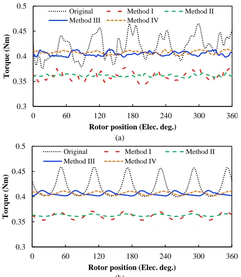
By using the torque transducer, the transient torque waveforms of VFRMs with different rotors are measured, as shown in Fig. 22. During the experiment, the AC current Iq and
DC current Idc are kept the same. It can be clearly observed that
the torque ripple of the original machine is significantly mitigated by the rotor shaping methods. Fig. 23 further compares the average torque under different currents. It is confirmed that the average torque of Methods III and IV are larger than those of Methods I and II, and slightly smaller than that of the original machine. Fig. 24 compares the variation of torque ripple against current. It can be seen that the measurement results are slightly larger than those predicted by FEA, especially at light load. This is mainly due to noise in the transient torque caused by the test rig. Nevertheless, the torque ripple is significantly reduced with the proposed rotor shaping methods. As expected, Methods II, III and IV show better performance than Method I. Regarding the variation of torque ripple with load, the torque ripples in machines with shaped rotors keep stable, whereas that of the original machine is continuously increasing with the current. Under rated load condition, the rotor shaping methods have even better torque
ripple mitigation performance.
C. Torque-speed curves
Finally, the torque-speed curves of the prototypes are measured, as shown in Fig. 25. The measured results are slightly smaller than the FEA predicted ones, especially in the flux weakening region. This is mainly due to the end effect and minor distortion in excitation in the high speed region. It can be found that:
(a) Due to the reduced back-EMFs, the constant torque regions of the VFRMs with rotor shaping methods I and II are slightly wider than those of the original VFRM and the VFRMs with rotor shaping methods III and IV.
(b) It is confirmed that the VFRMs with rotor shaping methods III and IV have equivalent output torque performance as the original VFRM regardless of the operation speed.
(a)
[image:9.612.321.558.248.517.2](b)
Fig. 20. Measured and FEA predicted waveforms of back-EMFs for VFRMs with different rotors (Idc=2A, rotating speed is 400rpm). (a) Measured. (b) FEA
predicted.
Fig. 21. Spectra of measured back-EMFs for VFRMs with different rotors. (Idc=2A, rotating speed is 400rpm).
-6 -4 -2 0 2 4 6
0 60 120 180 240 300 360
B
ack
-E
MF
(
V
)
Rotor position (Elec. deg.) Original
Method I
Method II
Method III
Method IV
-6 -4 -2 0 2 4 6
0 60 120 180 240 300 360
B
ack
-E
MF
(
V
)
Rotor position (Elec. deg.) Original
Method I
Method II
Method III
Method IV
0 1 2 3 4 5 6
0 1 2 3 4 5 6 7 8 9 10
B
ack
-E
M
F
(
V
)
Harmonic order
Original
Method I
Method II
Method III
[image:9.612.322.559.561.691.2](a)
(b)
Fig. 22. Measured and FEA predicted torque waveforms for VFRMs with different rotors. (Idc=2A, rotating speed is 80rpm). (a) Measured. (b) FEA
predicted.
(a)
[image:10.612.55.292.48.320.2](b)
Fig. 23. Variations of average torque against current (Iq=Idc). (a) Measured. (b)
FEA predicted.
VII. CONCLUSION
In this paper, four novel rotor shaping methods, i.e., eccentric circular, inverse cosine, inverse cosine with 3rd harmonic and multi-step shaping methods, were proposed and investigated for torque ripple mitigation in VFRMs. Their design criteria were illustrated and their electromagnetic perfo-
(a)
[image:10.612.322.558.50.318.2](b)
Fig. 24. Variations of torque ripple against current (Iq=Idc). (a) Measured. (b)
FEA predicted.
Fig. 25. Torque-speed curves of VFRMs with and without rotor shaping methods (Copper loss is 30W).
rmance were comparatively investigated. It was found that: (a) All the methods are capable of mitigating torque ripple, improving THD of back-EMF, reducing core loss and suppressing acoustic noise, albeit with a sacrifice of average torque.
(b) The inverse cosine shaping method is the best one in torque ripple mitigation. It is able to reduce the torque ripple of VFRMs to only 6% of the original machine, but at a cost of 10% average torque.
The inverse cosine with 3rd harmonic and multi-step shaping methods are able to reduce the torque ripple to 8-10% of the original machine at a cost of only 3% average torque. They are the best methods among the four.
The eccentric circular shaping method is the weakest one, only managing to reduce the torque ripple to 34% of the original machine with an 11% reduction in the average torque.
(c) The proposed rotor shaping methods are not applicable to VFRMs with 6k/(6i±2)k stator/rotor pole combinations.
All the analyses were verified by both FEA and experimental
0.3 0.35 0.4 0.45 0.5
0 60 120 180 240 300 360
T
orque
(N
m
)
Rotor position (Elec. deg.)
Original Method I Method II
Method III Method IV
0.3 0.35 0.4 0.45 0.5
0 60 120 180 240 300 360
Tor
que
(
Nm
)
Rotor position (Elec. deg.)
Original Method I Method II
Method III Method IV
0.15 0.25 0.35 0.45 0.55
1.2 1.5 1.8 2.1 2.4 2.7
A
ver
age
torque
(N
m
)
Current (A) Original
Method I
Method II
Method III
Method IV
0.15 0.25 0.35 0.45 0.55
1.2 1.5 1.8 2.1 2.4 2.7
A
verage
torq
ue
(N
m
)
Current (A) Original
Method I
Method II
Method III
Method IV
0 20 40 60 80 100 120
1.2 1.5 1.8 2.1 2.4 2.7
T
orque
ri
pp
le
(m
N
m
)
Current (A)
Original Method I
Method II Method III
Method IV
0 20 40 60 80 100 120
1.2 1.5 1.8 2.1 2.4 2.7
T
orque
ri
pp
le
(m
N
m
)
Current (A)
Original Method I
Method II Method III
Method IV
0 0.1 0.2 0.3 0.4 0.5 0.6 0.7 0.8
0 400 800 1200 1600 2000
Tor
que
(
Nm
)
Speed (rpm)
Original-FEA Original-Measure
Method I-FEA Method I-Measure
Method II-FEA Method II-Measure
Method III-FEA Method III-Measure
[image:10.612.322.561.354.477.2] [image:10.612.55.291.360.632.2]tests on a 6/7 VFRM prototype. It is worth noting that the analyses and methods presented in this paper are applicable to other salient pole reluctance machines and VFRMs with integrated AC and DC excitation [9][10], as well as using other number of points in the multi-step shaping method.
REFERENCES
[1] T. Fukami, Y. Matsuura, K. Shima, M. Momiyama, and M. Kawamura,
“Development of a low-speed multi-pole synchronous machine with a
field winding on the stator side,” in Proc. Int. Conf. Elect. Mach., Rome,
Italy, 2010, pp. 1–6.
[2] X. Liu, Z. Q. Zhu and Z. P. Pan, “Analysis of electromagnetic torque in
sinusoidal excited switched reluctance machines having DC bias in
excitation,” in Proc. Int. Conf. Elect. Mach., Sept. 2012, pp. 2882-2888.
[3] T. J. E. Miller, Electronic Control of Switched Reluctance Machines. Oxford, 2001.
[4] P. J. Lawrenson, J. M. Stephenson, P. T. Blenkinsop, J. Corda, and N. N.
Fulton, “Variable-speed switched reluctance motors,” Inst. Elect. Eng.
Elect. Power Appl., vol. 127, no. 4, pp. 253–265, Jul. 1980.
[5] C. H. Lee, “Vernier motor and its design,” IEEE Trans. Power App. Syst.,
vol. 82, no. 66, pp. 343–349, Jun. 1963.
[6] K. C. Mukherji, “Vernier reluctance motor,” Proc. Inst. Elect. Eng., vol.
121, no. 9, pp. 965–974, Sep. 1974.
[7] O. Ojo and Z. Wu, “Synchronous operation of a dual-winding reluctance
generator,” IEEE Trans. Energy Convers., vol. 12, no. 4, pp. 357-362,
Dec. 1997.
[8] S. Jia, R. Qu, J. Li, and D. Li, “Principles of stator DC winding excited
Vernier reluctance machines,” IEEE Trans. Energy Convers., vol. 31, no.3, pp. 935-946, Sept. 2016.
[9] X. Liu, Z. Q. Zhu, M. Hasegawa, A, Pride, and R. Deodhar, “Vibration
and noise in novel variable flux reluctance machine with DC-field coil in
stator,” in Proc. Int. Conf. Power Electron. Motion Control, Jun. 2012,
pp.1100-1107.
[10] J. Shaofeng, Q. Ronghai, and L. Jian, “Design considerations and
parameter optimization of stator wound field synchronous machines
based on magnetic the gear effect,” in Proc. ECCE, Sept. 2015, pp.
5195-5202.
[11] X. Liu and Z. Q. Zhu, “Electromagnetic performance of novel variable
flux reluctance machines with DC-field coil in stator,” IEEE Trans. Magn., vol. 49, no. 6, pp. 3020-3028, Aug. 2012.
[12] T. Fukami, Y. Matsuura, K. Shima, M. Momiyama, and M. Kawamura,
“A multi-pole synchronous machine with nonoverlapping concentrated
armature and field winding on the stator,” IEEE Trans. Ind. Electron.,
vol. 59, no. 6, pp. 2583–2591, Jun. 2012.
[13] L.R. Huang, J.H. Feng, S.Y. Guo, J.X. Shi, W.Q. Chu, and Z.Q. Zhu,
“Analysis of torque production in variable flux reluctance machine,”
IEEE Trans. Energy Convers., vol. 32, no.4, pp. 1297-1308, Apr. 2017. [14] L.R. Huang, Z.Q. Zhu, J.H. Feng, S.Y. Guo, J.X. Shi, and W.Q. Chu,
“Analysis of stator/rotor pole combinations in variable flux reluctance
machines using magnetic gearing effect”, in IEEE Energy Conversion
Congress and Exposition (ECCE2017), pp. 3187-3194, Oct. 2017. [15] Z. Q. Zhu, B. Lee, Xu Liu, “Integrated field and armature current control
strategy for variable flux reluctance machine using open winding,” IEEE
Trans. Ind. Appl., vol. 52, no. 2, pp. 1519–1529, Mar./Apr. 2016. [16] Z. Q. Zhu, B. Lee, “Integrated field and armature current control for dual
three-phase variable flux reluctance machine drives,” IEEE Trans. Energy Convers., vol. 32, no.2, pp. 447-457, Jun. 2017.
[17] S. A. Evans, “Salient pole shoe shapes of interior permanent magnet
synchronous machines,” in XIX Int. Conf. on Electrical Machines
(ICEM), Rome, Italy, Sept. 6-8, 2010, pp. 1-6.
[18] K. Wang, Z. Q. Zhu, G. Ombach, and W. Chlebosz, “Optimal rotor shape
with third harmonic for maximizing torque and minimizing torque ripple
in IPM motors,” in Proc. 20th ICEM, Marseille, France, Sep. 2012, pp.
397–403.
[19] K. Wang, Z. Q. Zhu, and G. Ombach, “Torque improvement of
surface-mounted permanent-magnet machine using 3rd order harmonic,” IEEE Trans. Magn., vol. 50, no. 3, Mar. 2014.
[20] N. K. Sheth, K. R. Rajagopal, “Variations in overall developed torque of a
switched reluctance motor with airgap nonuniformity,” IEEE Trans.
Magn., vol. 41, no. 10, pp. 3873–3795, Oct. 2005.
[21] J. Hur, G.H. Kang, J. Y. Lee, and J. P. Hong, “Design and optimization of
high torque, low ripple switched reluctance motor with flux barrier for
direct driving,” in Proc. 39th IAS Annu. Meeting, 2004, pp. 401–408.
[22] J. W. Lee, H. S. Kim, B. I. Kwon, and B. T. Kim, “New rotor shape design
for minimum torque ripple of SRM using FEM,” IEEE Trans. Magn., vol.
40, no. 2, pp. 754–757, Mar. 2004.
[23] N. K. Sheth and K. R. Rajagopal, “Torque profiles of a switched
reluctance motor having special pole face shapes and asymmetric stator
poles,” IEEE Trans. Magn., vol. 40, no. 4, pp. 2035–2037, Jul. 2004.
[24] Y. K. Choi, H. S. Yoon, and C. S. Koh, “Pole-shape optimization of a switched-reluctance motor for torque ripple reduction,” IEEE Trans. Magn., vol. 43, no. 4, pp. 1797–1800, Apr. 2007.
[25] T. Ogasawara, H. Goto, and O. Ichinokura, “A study of rotor pole shape
of in-wheel direct drive SR motor,” in Proc. of the Power Electronics and Applications (EPE), Lille, France, Sep. 2013, pp. 1–7.
[26] S. D. Chishko, Y. Tang, J. J. H. Paulides, and E. A. Lomonova, "DC excited flux-switching motor: Rotor structural optimization," in 17th International Conference on Electrical Machines and Systems (ICEMS), Hangzhou, China, Oct. 2014, pp. 2867-2871.
L.R. Huang received the B.Eng. and M.Sc.
degrees in electrical engineering from Zhejiang University, Hangzhou, China, in 2012 and 2015, respectively. Since 2015, he has been working toward the Ph.D. degree in the Department of Electronic and Electrical Engineering, University of Sheffield, U.K.
His major research interests include design and application of reluctance machines and permanent magnet machines.
J.H. Feng (S’06) received his B.S. and M.S.
degrees in Electrical Machinery Control from Zhejiang University, China in 1986 and 1989, respectively, and Ph. D. degree in Control Theory and Control Engineering from Central South University, China in 2008. Since 1989, he has been with CRRC Zhuzhou Institute Co. Ltd., Zhuzhou, China, where he is presently the Vice President and Chief Technology Officer. He has published a number of journal and conference proceedings papers. His research interests are modeling, control, and communication of electrical systems, rail networks and high-speed trains. He is also a Guest Professor in Southwest Jiaotong University, Tongji University and Central South University.
S.Y. Guo is a professorial senior engineer. She graduated from Central South University in December 1981, and serves as the chief technical expert in CRRC Zhuzhou Institute Co., Ltd. in the field of R&D of the electric machine systems for railway locomotive and electrical vehicle applications.
J.X. Shi received the B. Eng. and M. Sc. degrees in electrical engineering from South China University of Technology, Guangzhou, China in 2010 and 2013, respectively. Since 2013, he has been with CRRC Zhuzhou Institute Co., Ltd.
His major research interests include design and application of permanent magnet machines for electrical vehicle applications.
Z.Q. Zhu (M’90–SM’00–F’09) received the B.Eng. and M.Sc. degrees in electrical and electronic engineering from Zhejiang University, Hangzhou, China, in 1982 and 1984, respectively, and the Ph.D. degree in electrical and electronic engineering from The University of Sheffield, Sheffield, U.K., in 1991.