Shear Panel in the Vicinity of Beam-Column Connections
- Component-Based ModellingGuan Quana, Shan-Shan Huanga, Ian Burgessa
aUniversity of Sheffield, Department of Civil and Structural Engineering, UK [email protected], [email protected], [email protected]
INTRODUCTION
The investigation of the “7 World Trade” collapse [1] in New York City indicated that the building was largely unaffected by the aircraft impacts, but collapsed due to the effect of prolonged fires. This was triggered by the failure of beam-to-column joints as a result of large thermal expansions of beams. Joints are among the key elements of buildings in fire. Their failure may initiate fire spread, and may lead to progressive collapse of a whole building.
[image:1.595.185.409.424.573.2]Several of the full-scale Cardington Fire Tests [2] indicated that shear buckling at the ends of the steel sections of composite beams (shown in Fig. 1) is very prevalent under fire conditions. This phenomenon, which has not been extensively studied, can have significant effects on the joints, as well as on the beams. In this paper, as a preliminary background study of beam-end buckling behaviour at elevated temperatures, shear buckling of the beam web of Class 1 beams has been studied at ambient temperature. The force-deflection relationship of the shear panel, from the initial post-buckling stage to failure, can be modelled by a simple component-based model. A range of 3D finite element simulations has been created using the ABAQUS software, in order to validate the component-based model over a range of geometries. Comparisons between the simple and FE models have shown that the proposed method provides sufficient accuracy to be developed further, and in due course to be embodied in global modelling of composite structures in fire conditions.
Fig. 1. Shear buckling phenomenon in Cardington Fire Test [2]
1 DEVELOPMENT OF THE THEORETICAL MODEL
two transverse stiffeners. These factors have been taken into account when creating the theoretical model.
The calculation is based on the principle of equality of the internal and external plastic work,
w f e
W W W (1) where Ww is the internal work of the beam web,
Wf is the internal work of the flanges,
We is the external work.
[image:2.595.337.492.287.432.2]For Class 1 cross-sections at ambient temperature it is reasonable to assume that the formation of plastic hinges on the flanges occurs before the web buckles inelastically. It is also assumed that the beam webs are composed of tensile and compressive strips. The total internal work done in the collapse (fracture) stage is the sum of the internal work of the web and the flanges. The external work is that done by displacement of t the external forces. At the failure stage, a fracture strain of 0.15 is used. When the equivalent plastic strain is 0.15, there is assumed to be fracture within the shear panel. The theoretical model is shown in Fig. 3.
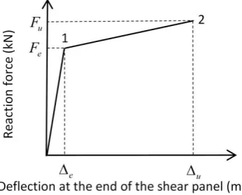
Fig. 2. Bi-linear force-deflection curve of shear panels Fig. 3. Theoretical model
2 FINITE ELEMENT ANALYSIS USING ABAQUS
The commercial finite element software ABAQUS was used to simulate the behaviour of beam web shear buckling in the vicinity of beam-column connections at ambient temperature. The S4R element [4] of ABAQUS was adopted. This is a four-noded shell element, which is capable of simulating buckling behaviour, and shows reasonable accuracy. A mesh sensitivity analysis was carried out, andan element size of 20mm x 20mm was found to provide optimum accuracy and efficiency. The Riks approach was used in order to identify the descending part of the force-displacement curve after inelastic buckling occurs.
2.1 Geometry of the beam
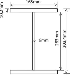
[image:2.595.81.254.288.427.2]Fig. 4. Image of finite element model Fig. 5. Cross section dimensions
2.2 Boundary conditions
Since the geometry under consideration is symmetric, only half of the beam was modelled. The whole beam is assumed to be fixed at both ends; boundary conditions for an axis of symmetry were applied to the mid-span of the beam except that restraint to thermal expansion (horizontal movement) was relaxed. Two rigid ‘plates’ were applied to the beam end and mid-span, and the boundary conditions were achieved by applying constraints to the reference point (the mid-point) of each rigid plate. The boundary conditions are shown in Fig. 6 and Table 1.
2.3 Material properties
The stress-strain relationship at room temperature, shown in Fig. 7, is based on the EC3 [5] constitutive model for structural steel at elevated temperatures. Since the strain hardening of steel is negligible at high temperature, it has been ignored in this study. To be consistent with the assumed stress-strain relationships at high temperatures, the same limiting strain at yield strength y, and ultimate strain u, are applied to the stress-strain curve at ambient temperature. The details of the material properties used in the ABAQUS models are shown in Table 2.
Reference Point 2
Reference Point 1
Beam end Mid span
Table 1. Boundary conditions Reference
point 1
Reference point 2
U1 1 1
U2 1 0
U3 1 0
UR1 1 1
UR2 1 1
UR3 1 1
[image:3.595.88.383.108.174.2]Note: U1, U2 and U3 are the translational degrees of freedom (DoF) in the x, y and z directions, respectively. UR1, UR2 and UR3 are the rotational DoFs in the x, y and z directions, respectively. ‘0' represents that a DoF is free, whereas ‘1’ means a DoF is restricted.
[image:3.595.85.550.405.620.2]Table 2. Material Properties
fy,θ (N/mm2)
εy,θ (%)
εt,θ (%)
εu,θ (%)
E
(N/mm2) 275 2 15 20 2.10×e5
Fig. 7.Stress-strain relationship of structural steel at ambient temperature used in modelling
3 VALIDATION AGAINST FINITE ELEMENT MODELLING
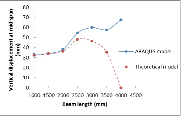
[image:4.595.133.437.581.774.2]Figs. 8 and 9 show a comparison of the load capacities (as applied vertical forces), and corresponding mid-span vertical displacements, between the theoretical model and the finite element analysis for beams of different lengths. In the theoretical model, the mid-span vertical deflection due to the transverse drift of the shear panel, as well as that caused by the bending of the beam, have been considered.
Fig. 9. Vertical displacement comparison for different beam lengths
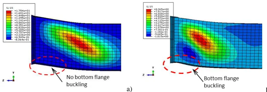
As can be seen from Fig. 8, the theoretical model compares well with the numerical model at ambient temperature. For the particular beam section analysed, the vertical displacements given by the two models agree well for beams shorter than 2.5m, whereas for longer beams the results given by the two models diverge. This happens because the failure mode switches from shear buckling of the web to bottom flange buckling as the beam length increases, as shown in Fig. 10. The scale in Fig. 10 shows the out-of-plane deflections given by ABAQUS. For a short (1.5m span) beam, shown in Fig. 10(a), the deflection of the web at fracture is about 18mm, which means that shear buckling can develop sufficiently. The bending moment at the end of the beam is relatively small, and little bottom flange buckling occurs. However, for a longer (4m span) beam, shown in Fig. 10(b), the beam-end bending moment is significant. The out-of-plane deflection at fracture is only about 8mm, which means that shear buckling of the beam web cannot develop sufficiently. Bottom flange bucking is much clearer in this case than for the short beam. The bottom flange buckling can result in rotation of the beam end, and has not so far been included in the theoretical analysis. This is probably the reason why the mid-span vertical deflections given by the two models diverge when the beam length is longer than a certain value (4m in this case).
[image:5.595.73.515.307.460.2]a) b)
Fig. 10. Out-of-plane deflection at failure point: a) Beam length = 1500mm; b) Beam length = 4000mm
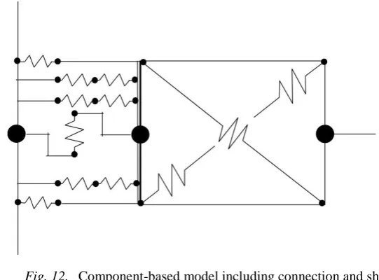
4 COMPONENT-BASED MODEL IN VULCAN
Fig. 11. Component-based model of shear panel
Fig. 12. Component-based model including connection and shear panel
5 CONCLUSIONS
A component-based theoretical model, based on tension field theory, has been created to predict the shear capacity and vertical deflection of shear panels for Class 1 beams, from the initial post-buckling stage to failure at ambient temperature. This model has been validated with finite element modelling using ABAQUS. For short beams, the main ‘failure’ mode is beam web shear bucking. Comparisons between the theoretical and FE models have shown that the proposed method provides satisfactory accuracy for short beams. For long beams, the main ‘failure’ mode is bottom flange buckling, which is not yet considered in the theoretical model. This leads to divergence of the vertical displacements between the theoretical and FE models when the beam is longer than 4m, for the particular cross-section analysed. The theoretical component-based model has been implemented in the software Vulcan, and shows sufficient accuracy to be developed further; in due course it will be embodied in global modelling of composite structures in fire.
REFERENCES
[1] Gann RG, 2008, Final Report on the Collapse of World Trade Center Building 7, Federal Building and Fire Safety Investigation of the World Trade Center Disaster, The National Institute of Standards and Technology (NIST), USA.
[2] Newman G, Robinson JT and Bailey CG, 2006, Fire safe design: A new approach to multi-storey steel-framed buildings, Second Edition, The Steel Construction Institute, Berkshire, UK.
[3] Rockey K and Skaloud M., 1972, “The ultimate load behaviour of plate girders loaded in shear”, Structural Engineering, Vol. 50, pp. 29-47.
[4] Hibbit D, Karlsson B and Sorenson P, 2005, ABAQUS reference manual v6.7, ABAQUS Inc, Pawtucket, USA.
[5] BS EN 1993-1-2, 2005, Eurocode 3. Design of steel structures. Part 1-2: General rules-Structural fire design, British Standards Institution, UK.
SHEAR PANEL IN THE VICINITY OF BEAM-COLUMN CONNECTIONS
- Component-Based Modelling Guan Quana, Shan-Shan Huanga, Ian Burgessa
aUniversity of Sheffield, Department of Civil and Structural Engineering, UK [email protected], [email protected], [email protected]
KEYWORDS: Shear buckling; Connections; Component-based model; Fire
6 ABSTRACT
The Cardington composite frame fire tests [1] indicated that shear buckling of beams in the vicinity of the beam-column joints, is very prevalent under fire conditions. This phenomenon can have significant effects on the adjacent connections at high temperatures. Firstly, shear buckling of the beam web can cause force redistribution in the column-face bolts. Secondly, transverse drift of the shear panel can contribute to its deflection. Previous researchers have investigated the behaviour of joints at high temperature, but buckling in the vicinity of connections has not so far been studied. As the most important part of a background study of beam-end buckling behaviour at elevated temperatures, shear buckling of the beam web of Class 1 beams has been studied at ambient temperature. A component-based analytical model of plastic buckling of the beam web shear panel has been created. This theoretical model has been extended to elevated temperatures. The force-deflection relationship of the shear panel from the initial post-buckling stage to failure can be predicted by the theoretical model. A range of 3D finite element models have been created using the ABAQUS software, in order to validate the component-based model over a range of geometries. Comparisons between the theoretical and FE models have shown that the proposed method provides a sufficient accuracy to be developed further, and in due course to be embodied in global modelling of composite structures in fire.
7 CONCLUSIONS
A component-based theoretical model based on the tension field theory has been created to predict the shear capacity and vertical deflection of shear panels for Class 1 beams, from the initial post-buckling stage to failure at ambient temperature. This model has been validated with finite element models using ABAQUS. For short beams, the main failure mode is beam web shear bucking. Comparisons between the theoretical and FE models have shown that the proposed method provides a good accuracy for short beams. For long beams, the main failure mode is bottom flange buckling, which is not yet considered in the theoretical model. This leads to the divergence of the vertical displacements between the theoretical and FE models when the beam is longer than 4m for the particular cross-section analysed. The theoretical component-based model has been implemented in the software Vulcan, and is with sufficient accuracy to be developed further, and in due course to be embodied in global modelling of composite structures in fire.
REFERENCES
[1] Gann RG, 2008. Final Report on the Collapse of World Trade Center Building 7, Federal Building and Fire Safety Investigation of the World Trade Center Disaster, The National Institute of Standards and Technology (NIST), US.
[2] Newman G, Robinson JT, Bailey CG, 2006. Fire safe design: A new approach to multi-storey steel-framed buildings, Second Edition, The Steel Construction Institute, Berkshire.
[3] Rockey K., Skaloud M., 1972. “The ultimate load behaviour of plate girders loaded in shear”, Structal Engineering, Vol. 50, pp. 29-47.
[4] Hibbit D, Karlsson B, Sorenson P, 2005. ABAQUS reference manual 6.7, ABAQUS Inc, Pawtucket. [5] CEN. BS EN 1993-1-2, 2005. Eurocode 3. Design of steel structures. Part 1-2: General rules-Structural
![Fig. 1. Shear buckling phenomenon in Cardington Fire Test [2]](https://thumb-us.123doks.com/thumbv2/123dok_us/7957733.198211/1.595.185.409.424.573/fig-shear-buckling-phenomenon-cardington-test.webp)