Control of spatially rotating structures in
diffractive Kerr cavities
A
LISONM. Y
AO,
1,*C
HRISTOPHERJ. G
IBSON,
1 ANDG
IAN-L
UCAO
PPO11SUPA and Department of Physics, University of Strathclyde, Glasgow G4 0NG, Scotland, UK *[email protected]
Abstract: Turing patterns in self-focussing nonlinear optical cavities pumped by beams carrying orbital angular momentum (OAM)mare shown to rotate with an angular velocityω=2m/R2on
rings of radiiR. We verify this prediction in 1D models on a ring and for 2D Laguerre-Gaussian
and top-hat pumps with OAM. Full control over the angular velocity of the pattern in the range
−2m/R2 ≤ ω ≤ 2m/R2 is obtained by using cylindrical vector beam pumps that consist of
orthogonally polarized eigenmodes with equal and opposite OAM. Using Poincaré beams that consist of orthogonally polarized eigenmodes with different magnitudes of OAM, the resultant angular velocity isω=(mL+mR)/R2, wheremL,mRare the OAMs of the eigenmodes, assuming good overlap between the eigenmodes. If there is no, or very little, overlap between the modes then concentric Turing pattern rings, each with angular velocityω = 2mL,R/R2 will result. This can lead to, for example, concentric, counter-rotating Turing patterns creating an optical peppermill-type structure. Full control over the speeds of multiple rings has potential applications in particle manipulation and stretching, atom trapping, and circular transport of cold atoms and BEC wavepackets.
© 2019 Optical Society of America under the terms of theOSA Open Access Publishing Agreement
1. Introduction
Pattern formation is ubiquitous in nonlinear dynamical systems, the most famous examples being Turing patterns in reaction-diffusion systems [1] and Benjamin-Feir modulational instability in water waves [2]. In propagation through self-focusing nonlinear media with optical vortex beams, an azimuthal modulational instability leads to beam fragmentation as described in [3–6]. In optical cavities, instead, spontaneous spatial pattern formation results due to the Turing instability deriving from the interplay of nonlinearity, cavity detuning and a spatial coupling, such as diffraction or dispersion. Such systems are very well described by the Lugiato-Lefever equation for optical cavities with plane-plane mirrors [7]. In this paper we consider the effect of pumping optical cavities containing a self-focussing Kerr medium with beams carrying optical angular momentum (OAM) and show the formation of rotating Turing structures. We derive analytical expressions that fully describe these two-dimensional rotating Turing structures in single field (scalar) Kerr resonators and confirm our predictions numerically using pumps consisting of Laguerre-Gaussian modes or top-hat beams carrying OAM. In particular, we demonstrate that the number of intensity peaks in the patterns is determined by the power and OAM of the input pump, as well as the cavity detuning. We also demonstrate that the angular velocityωof the patterns is fully determined by the OAMmof the pump and the radiusRof the ring structure according
toω=2m/R2. Spatial structures rotating on a transverse ring including cavity solitons can be
considered as slow light pulses with fully controllable speed and structure for use in optical quantum memories and delay lines. These studies complete early investigations that focused on optical parametric oscillators, semiconductor heterostructures and photorefractive materials, respectively [8–10].
Fully-structured light consisting of a vector superposition of two scalar OAM-carrying Laguerre-Gaussian eigenmodes with orthogonal circular polarizations [11–13], has attracted increasing
#374411 https://doi.org/10.1364/OE.27.031273
attention for a number of applications [14–17]. The inclusion of a second field component in the light-matter interaction inside the cavity offers further degrees of control in the shape and polarization of the pump and the resultant nonlinear structures. In particular we show how the use of fully-structured light to pump the cavity allows us full control over the angular velocity of the Turing structures. Using numerical simulations we demonstrate how biasing cylindrical vector (CV) beam pumps - orthogonally polarized eigenmodes with equal and opposite OAM (mL=−mR) - allows us to produce patterns with angular velocity−2m/R2 ≤ω≤2m/R2and that Poincaré pumps - orthogonally polarized eigenmodes with different magnitudes of OAM - produce patterns with angular velocityω =(mL+mR)/R2. Applications of these rotating structures to particle manipulation, optical beam shaping and photonic devices is discussed. Finally we give examples of fields with counter-rotating Turing patterns that we refer to as an optical peppermill, that may be of particular interest in trapping, manipulating and deforming biological specimens.
2. Lugiato-Lefever case
We start with the description of Kerr media in plane-plane optical cavities through the well-known Lugiato-Lefever equation (LLE) in two transverse dimensions [7]:
∂tE=P− (1+iθ)E+iβ|E|2E+i∇2E (1)
whereEis the intracavity field,Pis the amplitude of the input pump,θis the detuning between
the input pump and the closest cavity resonance,βis proportional to the Kerr coefficient of the nonlinear material, and the term with the transverse Laplacian∇2describes diffraction and can
be written in either Cartesian or polar coordinates. The time scale has been normalised byτpthe mean lifetime of photons in the cavity given by 2L/cT for a unidirectional ring cavity and by
4L/cT for a Fabry-Perot cavity, withLbeing the cavity length,T the (intensity) transmission
coefficient of the cavity mirrors andcthe speed of light in vacuum. The transverse spatial scale
(x,y) has been normalised by
a= cτp
2K 1/2
= cλτ
p 4π
1/2 =
L kT
1/2
(2)
wherekandλare the wavevector and wavelength of the input light, respectively.
In order to derive some analytical results, we note that LG modes withm>0 can be considered
as rings of fixed radiusRmnormalised via (2). We therefore express the transverse Laplacian in polar coordinates(R,ϕ)and, asRcan be considered a constant, we can write the LLE Eq. (1) in
one angular transverse dimension:
∂tE=P− (1+iθ)E+iβ|E|2E+
i R2
∂2E
∂ϕ2 . (3)
As the focus of this work is the effect of pumping the ring with light carrying orbital angular momentum (OAM), we consider pumps of the form:
P=Pmeimϕ (4)
wherePmis a complex amplitude independent ofϕ, andmis an integer corresponding to the topological charge of the optical vortex. In this case we consider solutions of the form:
E(ϕ, t)=F(ϕ, t)eimϕ (5)
that satisfy the equation: ∂F
∂t =Pm−
1+i
θ+m2
R2 F+iβ|F|
2F−2m R2
∂F
∂ϕ +
i R2
∂2F
One effect of the OAM-dependent solution (5) is that the detuning is modified by an amount
m2/R2. We note that this phase shift is independent of the sign of OAM (i.e. left- or right-hand
phase circulation) and the overall effect is to increase the cavity off-tuning for positiveθand to (partially) compensate the detuning in the case of negativeθ. Moreover, this OAM-dependent detuning increases when the radius of the ring decreases.
2.1. Homogeneous stationary states
For any value ofm, the homogeneous stationary solutionsFsare obtained from:
Pm=Fs
1+i
θ+m2
R2 −βIs (7)
whereIsis the intensity of the stationary solutionIs=|Fs|2 =|Es|2. Once the stationary intensity
Isis selected, the amplitude and phase of the pump field are obtained from (7) implicitly. We highlight the radial dependent detuning term that comes from the OAM associated with the helical phase of the stationary solution (5) and note that form,0, homogeneous stationary states
of Eq. (6) correspond to stationary states for the fieldEthat are not homogeneous in the phaseϕ.
2.2. Turing instabilities on the ring: m=0
Form=0,F=Eand Eq. (6) is equivalent to Eq. (3). Both Eqs. (1) and (3) are well known to
display a Turing instability of the homogeneous stationary state. In order to analyze the stability of the solutions we introduce a small perturbation with wavevectork:E=Eseλ(k)δEand neglect terms nonlinear inδE,δE∗. Performing a linear stability analysis (LSA) we find that above the
Turing instability, both Eqs. (1) and (3) withm=0 experience the linear growth of a perturbation
with wavevectorkgiven by [7,18] :
λ(k)=−1± q
4∆βIs−3β2I2s −∆2 . (8)
where∆=θ+k2. It is clear from Eq. (8) that if the square root is imaginary, there are no
instabilities since both eigenvalues have negative real part. For a real eigenvalue to be positive, the quantity in the square root has to be larger than one. The instability boundary where the square root in (8) is exactly equal to one, provides a relation between the detuning∆(which
contains the wavevectork) and the stationary intensityIs:
∆=2βIs±
q
β2I2
s −1 . (9)
This shows that there is an instability threshold in the stationary intensity given byIsc=1/β. For
a givenIs>Ics =1/βthe most unstable wavevector is obtained by finding the maximum of the square root in (8) when changing∆:
kc=
p
2βIs−θ. (10)
Above threshold,Npeaks appear along the ring separated by a distance given by, or close to, the
wavelength of the Turing structureΛc=2π/kc. Note that for a ring of circumference 2πR, the
number of peaks isN=2πR/Λc=Rp2βIs−θ, and exactlyNpeaks fit inside a ring of radiusR to satisfy the periodic boundary conditions.
2.3. Rotating solutions:m,0
We now consider the case of pumps carrying OAM, i.e.m,0. Above the instability threshold
velocity. We start by rearranging Eq. (6) such that the first order derivatives are on the l.h.s.: ∂F
∂t +
2m R2
∂F
∂ϕ =Pm−
1+i
θ+m2
R2 F+iβ|F| 2F+ i
R2
∂2F
∂ϕ2 . (11)
Note that this is the generalization of the analysis of a tilted wave front [19] to polar coordinates on a ring. We then consider travelling wave solutions to Eq. (11) of the formF(q)that depend on
the variablesϕandtthrough
q=ϕ−ωt, (12)
whereωis the angular velocity. In this case we can write the l.h.s. of Eq. (11) as ∂F
∂t +
2m R2
∂F
∂ϕ = ∂F(q)
∂q
−ω+2m R2
. (13)
Clearly this equals zero when
ω=2m
R2 , (14)
and thus there exist rotating solutionsF(q) with angular velocity ω = 2m/R2 that can be
determined via
Pm=
1+i
θ+m2
R2 F−iβ|F| 2F− i
R2
∂2F
∂q2 . (15)
Apart from a renormalization of the detuning, Eq. (15) is equivalent to the stationary solutions of Eqs. (6) and (3) form=0. This means that all the results of them=0 case can be applied to
them,0 case starting from the trivial homogeneous state that we have already seen in Eq. (7).
These travelling wave solutions are equivalent to stationary solutions found using the retarded timeτ=t−ϕ/ω, as described in Appendix A.
Among these travelling waves solutions we can identify Turing patterns form,0 arising from
Eq. (15) by analogy with them=0 case. Travelling wave Turing patterns are rotating solutions
of Eq. (11) satisfying (8) upon the redefinition of the space-dependent detuning
∆=θ+m 2
R2 +k
2 (16)
and most unstable wavevector:
kc=
r
2βIs−θ−
m2
R2 . (17)
The wavelength of the Turing structureΛc=2π/kcand the number of peaks
N=2πR/Λc=R
r
2βIs−θ−
m2
R2 (18)
now both depend on the OAM and the radius of the ring. Note that for detuningθdifferent from 2βIsand form2/R2small, e.g. for small magnitudes of OAM and large radii, the critical wavevectors from (10) and (17), and hence the number of peaks, are approximately the same. We also note that, at difference from the case of pure propagation [3–6], the number of intensity peaks is crucially dependent on the cavity detuningθand the input pump intensityIs. Historically,
expressions for the angular velocity similar to (14) had been obtained and applied to rotating domain walls in optical parametric oscillators [8] and used as numerical ansatz for self-trapped necklace-ring beams in a self-focusing nonlinear Schrödinger equation [20].
3. Numerical simulations
Although the analysis in the previous section assumed a quasi-1D geometry (rings of fixed radius), all of our numerical simulations are performed in 2D.
3.1. Laguerre-Gaussian pumps
We start by using the well-known split-step Fourier method to numerically integrate Eq. (1) using a Laguerre-Gaussian pump with radial indexp=0 [21]:
LGm0(r,φ)= s
2 π|m|!
1
w0 r√2
w0 !|m|
exp −r2
w20 !
eimϕ=Pmeimϕ, (19)
wheremis the OAM andw0is the beam waist. All the results that we present are independent of
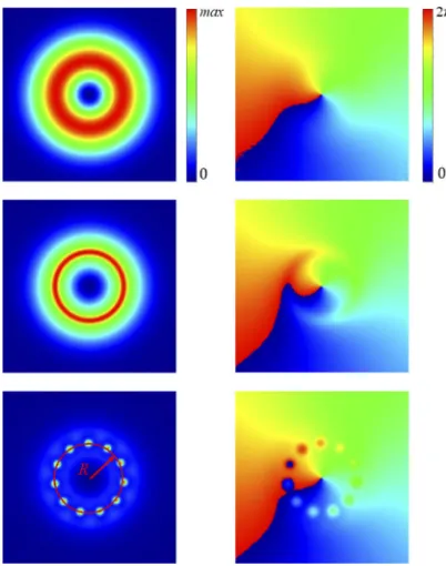
[image:5.612.204.405.286.541.2]the numerical method used for integration. In Fig.1we show the time evolution of the field from an LG mode-like ring to a number of bright peaks equally spaced around a ring of maximum intensity.
Fig. 1.Density plot of intensity (left) and phase (right) during evolution to pattern formation form = 1. Parameters are: Is = 1.44,θ = 1,β =2/3,w0 = 15.0 (normalised units). Top-Bottom:t=2, 30, 500.
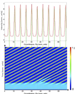
For our given parameters,Is=1.44,θ=1,β=2/3,w0=15.0 (normalised units), we find that 11 peaks form on a ring of radiusR=11.0±0.5, as shown in the top panel of Fig.2. This is in
accordance with the closest integer value from our predicted value, using Eq. (18), of 10.5±0.5.
From Eq. (14) we predict that the peaks should rotatecounter-clockwiseat a constant angular
velocityω=0.0164±0.0003. To calculate the angular velocity in the numerical results we plot
the time evolution of the field at radiusR, as shown in the bottom panel of Fig. 2, where the
diagonal red lines correspond to the peaks of intensity. Angular velocityω=∆ϕ/∆t=∆s/(R∆t)
where∆sis the distance a peak travels around the circumference of the circle in a time∆t.
Fig. 2. (Top) Intensity of the field at radiusRatt=1000 showing 11 peaks. (Bottom)
Time evolution of the intensity at radius R fromt = 0 tot = 1000. Parameters are: Is=1.44,θ=1,β=2/3,w0=15.0,m=1.
We repeated our simulations for an LG pump withm=−1, and found that the now peaks
rotatedclockwiseat the same speed,ω =0.0164±0.0003, again as predicted from Eq. (14).
However, when we measured the angular velocities form=2, 3, 4 & 5 numerically we found that
in each caseω=0.0164±0.0003, as shown by the blue line in Fig. 3i.e. the angular velocity
was constant and apparently independent of the OAM of the beam. We can explain this result by noting that the radius of maximum amplitude of the field is OAM-dependent: the red line in Fig.3shows our numerical results are in good agreement with the predicted angular velocities calculated using the measured values ofRfor each OAM.
For any LG mode the radius of maximum amplitude isrmax=w0
p
|m| /2. Substituting this
into the angular velocity we findω=2m/r2=±4/w20. We therefore expect the angular velocity
of LG modes to be independent ofmbut inversely proportional to the beam waist,w0.
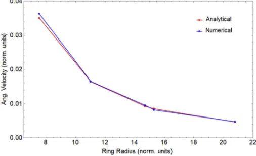
To confirm this we numerically integrated Eq. (1) using LG pumps withm=1 and beam
waists of 10.0, 15.0, 20.0, which formed rings of bright spots at radii 19.23, 28.11, 37.5, and with a beam waist of 25.0, which formed two rings of bright spots at radii 39.0, 53.0. Figure4 shows that we have very good agreement between the angular velocity of the rings measured numerically (blue line) and the predicted values from Eq. (14) using the measured radii (red line).
These measurements simultaneously confirm the direct proportionality of the angular velocity to the OAM indexmand inverse proportionality to the square of the radius of the input ring
Fig. 3. Angular velocityω vs OAM index mfor LG input pumps. Parameters are: Is=1.44,θ=1,β=2/3,w0=15.0,m=1−5. The blue line corresponds to numerical simulations of Eq. (1), the red line to the analytical result Eq. (14).
Fig. 4.Angular velocityωvs the radius of LG input pumps withm=1. Parameters are: Is=1.44,θ=1,β=2/3,w0=10.0−25.0,m=1. The blue line corresponds to numerical
simulations of Eq. (1), the red line to the analytical result Eq. (14).
solitons in semiconductor microresonators [9] and on rotating patterns in photorefractive media in single mirror feedback configurations [10], the pump radius and the OAM index where changed simultaneously leading to weak dependencies of the angular velocity on the OAM index (see Fig. 3. We believe that both these investigations provide support to the universality of Eq. (14) when one includes the changing radius of the input pump of LG modes with different OAM.
3.2. Top-hat pumps carrying OAM
We next consider the case where the input pump has a top-hat shape amplitude multiplied by an azimuthal phase:
P=Pm
2 [1−tanh(S(r−rt))]eimϕ. (20) HerePmis a spatially independent complex amplitude,Sandrtcontrol the steepness of the sides and the radius of the top-hat, respectively, andmis an integer corresponding to the topological
[image:7.612.179.432.315.469.2]Diffraction due to the finite size of the pump induces concentric rings, whose amplitude decreases from the outer ring inwards form= 0, as shown in Fig. 5(a). The amplitude of
the outermost ring increases with the steepness of the sides of the pump and this can allow its intensity to trigger the Turing instability, see the red line in Fig.6in a comparison withIsc=1/β,
and an azimuthal pattern forms on the ring. Once the pattern has formed on the outer ring (left panel Fig.7), we observe a sequence of azimuthal instabilities from the outer to the inner ring. Each patterned ring forms a number of peaks separated by the critical wavelength corresponding to the radius of the particular diffraction ring. The final patterns form=0 are stationary and
close to the centre of the pump they have a hexagonal structure, see Fig. 5(b), typical of that found for plane-waves [7]. Patterns on the outermost diffraction rings, however, are similar to the well-known daisy or sunflower patterns as observed, for example, in VCSELs with an electronic pump with a steep oxide confinement [22–26]. When the pump carries OAM, i.e.m,0, the
phase at the centre of the pump is undefined and hence the field at the origin has to be zero, as is typical for Laguerre-Gaussian modes [27]. The physical effect of this on-axis vortex is the induction of diffractive rings close to the centre of the beam, see the dashed blue line in Fig. 6. In this case the intensity of theinnerring may exceedIcs and undergo an azimuthal Turing
instability. The distance between the concentric rings is close to the critical wavelengthΛcalong
the radial direction. Once the Turing pattern has formed on the inner ring we observe a sequence of azimuthal instabilities taking place from the inner to the outer ring. As before, azimuthal peaks are separated by the critical wavelength corresponding to the radial length of the particular diffraction ring, modified by the factorm2/R2as shown in Eq. (17). Note: The effect of the
factorm2/R2on the wavelength is stronger towards the centre of the beam where the radius is
smaller. Moreover, the size of the central vortex, and hence radius of the first diffraction ring, increases with increasing OAM,m. These effects alter the radial wavevector in the vicinity of the
[image:8.612.206.399.402.585.2]vortex and can prevent regular patterns from forming on the innermost rings.
Fig. 5.Time evolution of the intensity of a top-hat pump withm=0 (a)-(b) andm=1 (c)-(d).
Left-hand-side shows initial development of diffraction rings att=500, right-hand-side
shows the final intensity structure att=60, 000 form=0 and att=2, 000 form=1. When
the pump carries OAM (bottom) the diffraction rings have maxima on both outer and inner rings, there is a vortex in the centre, and the Turing patterns are arranged in concentric rings and rotate atω=2m/R2. Parameters are:Is=1.44,θ=1,β=2/3,S=3.0.
As mentioned above, the steepness of the top-hat pump, determined bySin Eq. (20), and also
Fig. 6. Cross-section of intensity of pump (black) and fields form=0 (red) andm=1
(blue) both displaying the radial modulation at the critical wavevectorkc. Green line is pump intensity threshold for Turing instability. Parameters are: Is =1.44,θ=1,β=2/3,S= 3.0,t=500.
Fig. 7. Formation of pattern for top-hat pump with OAMm =1 and steepnesses of S=3.0, 1.8, 1.9 left to right. ForS=3.0 the sides of the pump are steeper than the vortex
and so the pattern forms first on the outer ring (left image). ForS=1.8 the sides of the vortex
are steeper than the pump and so the pattern forms first on the inner ring (middle image). ForS=1.9 the steepnesses are almost balanced and so the pattern can form on the inner and
outer rings almost simultaneously (right image). Parameters are:Is=1.44,θ=1,β=2/3.
steepness, and/or the OAM of the pump we can control if the Turing instability first occurs on the inner or the outer ring, or even on both simultaneously. This is demonstrated in Fig.7for a top-hat pump with OAMm=1 and steepnesses ofS=3.0, 1.8, 1.9 from left to right. ForS=3.0
the sides of the pump are steeper than the vortex and so the pattern forms first on the outer ring (left image). ForS=1.8 the sides of the vortex are steeper than the pump and so the pattern
forms first on the inner ring (middle image). ForS=1.9 the steepnesses are almost balanced and
so the pattern can form on the inner and outer rings almost simultaneously (right image). Ring by ring azimuthal instabilities can occur from the outside to the inside, or vice versa depending on where the pattern is first formed, or may even collide.
Whatever the mechanism of ring excitation (innermost or outermost), form,0 Turing patterns
appear on the first excited ring and start to rotate before the next ring is excited. This leads to concentric Turing pattern rings where the peaks are seen to rotate at exactly the angular frequency given by (14) withRequal to the radius of the specific diffraction ring. It is interesting to compare
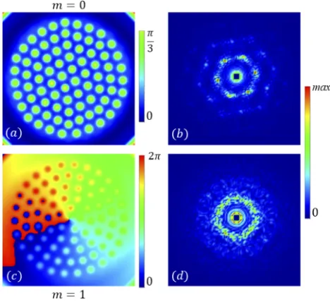
the final phase and final far-field distributions for them=0 andm=1 cases, as shown in Fig.8.
In both cases there are phase peaks where the local intensity also displays peaks. Form,0, the
[image:9.612.135.476.285.399.2]presence of rotating rings. Form=0 the hexagonal structure of the near-field is reflected in the
peaks of the far-field distribution (see Fig.8(b)) while the intensity peaks in the near field for
[image:10.612.188.422.189.403.2]m,0 are separated by the critical wavelengthΛcbut do not display any specific 2D geometry since they are located on rotating rings (see Fig.8(d)). Each ring is decoupled from the rest of the structure, meaning that they behave as independent 1D azimuthal structures although embedded in a fully 2D field. These rings maintain a fixed structure and rotation speed ad infinitum, unlike the case of optical vortices propagating in Kerr media.
Fig. 8. Final phase (a), (c) and final far-field distributions (b), (d) associated with the intensity structures of Fig.5(b) withm=0 and (d) withm=1, respectively. Parameters are: Is=1.44,θ=1,β=2/3,S=3.0.
In Fig. 9we plot the angular velocity of each ring that forms versus its radius for top-hat pumps withm=1 (red/cyan),m=2 (blue/magenta) andm=3 (green/orange). The numerical
results (solid lines) show excellent agreement with the analytical results (dashed line) calculated using (14) provided with the measured radii of the rotating rings. This confirms that scalar pumps carrying OAMmform independent Turing patterns on concentric rings of radiusReach
rotating with constant angular velocityω=2m/R2(see Fig. 5). For completion, we note that the
dynamics leading to the asymptotic ring rotation form,0 is much faster than that ofm=0
Fig. 9. Angular velocity vs ring radius for top-hat pumps withm=1 (red/cyan),m=2
(blue/magenta) and m = 3 (green/orange). Solid lines are numerical results, dashed
lines are calculated using (14) with measured radii of rotating rings. Parameters are:
Is=1.44,θ=1,β=2/3,S=3.0. Rotation on individual rings can be seen inVisualization
1.
4. Fully-structured pumps
Vector, or fully structured light (FSL), beams [11–13] have attracted increasing attention for a number of applications. These beams consist of a vector superposition of two scalar orbital angular momentum (OAM) carrying Laguerre-Gaussian (LG) eigenmodes with orthogonal circular polarizations:
®
E(r,φ)=cos(γ)LGmL
0 (r,φ) ®el+eiαsin(γ)LGm0L(r,φ) ®er, (21) whereγandαgive the relative amplitudes and phase, respectively, of the two modes. We assume throughout that each of the spatial modes takes the form of a Laguerre-Gaussian beam with radial indexp=0 as given in (19). The resultant beam has non-uniform spatial intensity, phase
and polarization distributions. To investigate the effect of using an FSL pump we usecoupled
Lugiato-Lefever equations [28]:
∂tEL,R=PL,R− (1+iθ)EL,R+i∇2EL,R+iβ
|EL,R|2+2|ER,L|2
EL,R. (22)
Note that if eitherELorERis zero, then the resultant beam is ascalarLG mode with spatially uniform right- or left-handed circular polarisation, respectively, and Eq. (22) reduces to the scalar LLE (1) that we have considered so far.
4.1. Cylindrical vector beam pumps
If the two modes have equal butoppositeOAM the resultant beam is know as acylindrical vector
(CV) beam [11,13]
®
E(r,φ)=cos(γ)LG−0m(r,φ) ®el+eiαsin(γ)LG0+m(r,φ) ®er. (23)
If the two modes have equal amplitude (γ=π/4), the pump will have no net OAM and a spatially
varyinglinearpolarization, as shown in Fig.10for eigenmodes with|m|=3. In this case we
but this time there is no rotation as the net OAM is zero. By changingγin (23) we change the relative amount of the two eigenmodes, i.e. the bias between the eigenmodes. Forγ=0(π/2)
the pump is a scalar left (right) circularly polarized beam with−m(+m)and we find exactly the
same behaviour as earlier; in particular, the output Turing pattern rotates atω=∓2m/R2. For
γ=π/4 the polarization is linear and the Turing pattern is stationary, as mentioned above. For
0<γ<π/4 the left circularly polarized mode dominates. The pump polarization is left ellptical
and the output field rotates clockwise (as we would expect form<0). Forπ/4<γ<π/2 the right
circularly polarized mode dominates. The pump polarization is right ellptical and the output field rotates counter-clockwise (as we would expect form>0). Note that the polarization structure
[image:12.612.178.429.224.333.2]does not rotate as there is no free propagation [29].
Fig. 10. Cylindrical vector beam with OAM ±3 with transversely structured linear polarization distribution shown by short red lines. Parameters are: Is=1.44,θ=1,β= 2/3,w0=15.0,γ=π/4,α=0.0.
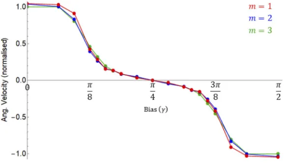
In Fig. 11we plot the angular velocity (normalised to 2m/R2) versus the bias parameterγ
for cylindrical vector (CV) beams with|m|=1 (red),|m| =2 (blue) and|m|=3 (green). By
controlling the bias (γ) between the two eigenmodes of the CV beam, we can fine tune the angular velocity of the output field from
−2m r2 ≤ω≤
2m
r2 . (24)
(Recall that LG modes all have the same angular velocity for any given beam waistw0.)
[image:12.612.162.452.482.648.2]4.2. Poincaré pumps
If the two modes havedifferentmagnitudes of OAM, the resultant beam is know as a Poincaré
beam [12]:
®
E(r,φ)=cos(γ)LGmL
0 (r,φ) ®el+eiαsin(γ)LGm0R(r,φ) ®er. (25) This carries a net OAM and the polarization can cover all polarization states on the Poincaré sphere. In Fig.12we plot the numerically measured values ofωR2against net OAM for different
Poincaré modes(mL,mR)=(−1, 1),(0, 1),(−1, 2),(1, 2),(−1, 3),(1, 3),(−2, 3),(2, 3)(red circles). We keepγ=π/4,α=0. We can see that there is very good agreement between our numerical
results and the blue line formL+mR, suggesting that for Poincaré beams, the angular velocity of the output field depends on the net OAM according to:
ω=mL+mR
[image:13.612.179.438.230.437.2]R2 . (26)
Fig. 12.Numerically measured values ofωR2against net OAM for different Poincaré modes
(mL,mR)=(−1, 1),(0, 1),(−1, 2),(1, 2),(−1, 3),(1, 3),(−2, 3),(2, 3)(red circles). Blue line ismL+mR. Parameters are:Is=1.44,θ=1,β=2/3,w0=15.0,γ=π/4,α=0.0.
4.3. Optical peppermill
Up until now we have only considered vector beams with some degree of spatial overlap. By considering eigenmodes with significantly different transverse radii such that there is very little interaction between them we can create, for example, counter-rotating rings of spots such as the optical peppermill shown in Fig.13. In this case the pump consists of a left -circularly polarized mode withmL=−1 and right-circularly polarized mode withmR=8. The output field has two rings of peaks, with the outer ring rotating counter-clockwise and the inner clockwise with the same angular velocityω=0.0375±0.0015. In principle we can produce even more complex
superpositions of modes as shown:
®
E(r,φ)=cos(γ)EL(r,φ) ®el+eiαsin(γ)ER(r,φ) ®er;
EL(r,φ)= nL
Õ
i=0
AiLGmi
q ÍnL
i=0A2i
;ER(r,φ)= nR
Õ
j=0
BjLGmj
q ÍnR
j=0B2j
, (27)
whereAiandBjare the contributions of left- and right-circularly polarized LG modes with OAM
in Fig. 13but with full and individual control over the speeds of each of the rings simply by biasing each with modes of opposite OAM and orthogonal polarisation, as in Fig.11.
Fig. 13.Optical peppermill constructed from orthogonally polarized modes withmL=−1 andmR=8. The inner ring rotates clockwise while the outer ring rotates counter-clockwise at the same angular velocity. Parameters are: Is =1.44,θ=1,β=2/3,w0 =10.0,γ= π/4,α=0.0. SeeVisualization 2.
5. Conclusion
We have demonstrated formation and rotation of spatio-temporal patterns in self-focussing nonlinear optical cavities pumped by beams carrying orbital angular momentum,m. For scalar
pumps we see the formation of a ring, or concentric rings, around an optical vortex that rotate at angular velocityω. Using a 1D Lugiato-Lefever model we find thatω=2m
R2, whereRis the radius of each ring. For a 1D azimuthal model this formula is exact but we confirm numerically that these angular velocities extend to the 2D case and demonstrate this using input pumps that are Laguerre-Gaussian modes and top-hat shaped pumps with OAM. We note that the radius of maximum intensity of an LG mode scales with the OAM s.t. LG beams with the same beam waistw0have the same angular velocity,ω=±4/w20. This means that we can control the angular
velocity of the patterns by the choice of: • OAM,m
• beam waist of LG pump,w0
• radius of top-hat pump,R.
Note that the numer of independent concentric rings that can form inside the top-hat depends on its diameter and the Turing pattern wavelength. Our analysis confirms earlier results on rotating domain walls in optical parametric oscillators and self-trapped necklace-ring beams in a self-focusing nonlinear Schrödinger equation.
Further control over the angular velocity of the pattern can be achieved using vector pumps with orthogonally polarization eigenmodes with good spatial overlap.
• Using cylindrical vector beams, that have eigenmodes with equal and opposite OAMm,
• Using Poincaré beams, that have eigenmodes with different magnitudes of OAMmL,mR,
the resultant angular velocity isω=(mL+mR)/R2.
If there is no, or very little, overlap between the modes then concentric Turing pattern rings, each with angular velocityω=2mL,R/R2will result. This can lead to concentric, counter-rotating Turing patterns creating, for example, an optical peppermill-type structure with full and individual control over the speeds of each counter-rotating ring of pattern. This has potential applications in particle manipulation by using the rotating peak intensities to dipole trap atoms, molecules and small particles. The differential rotation of concentric rings can also be applied to stretching and breaking of cells in a way analogous to optical stretchers [30]. Finally, rotating Turing patterns can be used to induce circular transport of cold atoms and BEC wavepackets using opto-mechanic nonlinearities instead of Kerr [31].
Appendix A. Retarded time transformation
Equation (11) is the LL equation on a ring for the fieldF(ϕ,t). By using the angular velocity (14)
it is possible to introduce retarded time transformations
ζ =ϕ; τ=t− ϕ
ω. (28)
s.t we can write
∂ ∂ϕ = ∂ ∂ζ − 1 ω ∂ ∂τ ; ∂ ∂t =
∂
∂τ. (29)
We can then write the l.h.s of Eq. (11) in the retarded time variables: ∂F
∂t +ω
∂F
∂ϕ = ∂F
∂τ +ω
∂F ∂ζ − 1 ω ∂F ∂τ =ω∂F
∂ζ and so we can write Eq. (11) as
ω∂F
∂ζ =Pm−
1+i
θ+m2
R2 F+iβ|F| 2F+ i
R2 ∂2
∂ζ2 +
1 ω2
∂2
∂τ2 −2
1 ω ∂ ∂ζ ∂ ∂τ
F. (30)
Steady states in the retarded variableζ, obtained by imposing∂F/∂ζ =0 in Eq. (30), correspond
exactly to the rotating solutions (15). Equation (30) can then be used to study the instabilities of the rotating solutions via, for example, appropriate linear stability analyses.
Appendix B. Rotating Turing patterns away from threshold
Here we investigate azimuthal Turing patterns on a ring due to pump fields carrying OAM well above threshold. From the analysis close to threshold, Turing patterns are spatially modulated structures with wavelengthΛc=2π/kcwherekcis the critical wavevector given by Eq. (17). We consider spatially modulated solutions of the ring LLE (3) of the form
E(ϕ, t)=F(ϕ, t)eimϕ=A[Q(ϕ, t)]exp{iΦ[Q(ϕ, t)]+iψ}eimϕ (31)
whereψis a constant phase andAandΦare amplitude and phase functions that are periodic in
the variableq=ϕ−ωtand spatially normalised for Turing patterns of wavevectorskc, given by: Q(ϕ, t)=kcR q=kcR(ϕ−ωt) (32)
whereωis the angular frequency. By replacing (31) in the ring LLE (6) one obtains:
−kcRω
∂ A
∂Q+iA
∂Φ
∂Q
exp(iΦ+iψ)= +Pm+
−
1+i
θ+m2
R2 A+iβA 3
+k2c "
i∂ 2A
∂Q2 −A
∂2Φ
∂Q2 −2
∂A
∂Q
∂Φ
∂Q−iA ∂
Φ
∂Q 2#
− 2mkcR R2
∂ A
∂Q+iA
∂Φ
This demonstrates that above threshold, Turing patterns with an amplitude and a phase that are spatially modulated at the critical wavevectorkcare solutions of Eq. (6) provided that they rotate at an angular velocityω=2m/R2and that they satisfy
Pmexp(−iψ)= 1+i
θ+m2
R2 A−iβA 3
−k2c "
i∂ 2A
∂Q2 −A
∂2Φ
∂Q2 −2
∂A
∂Q
∂Φ
∂Q−iA ∂
Φ
∂Q 2# )
exp(iΦ).
(34)
We have verified condition (34) by integrating Eq. (3) well above the threshold of pattern formation and for a variety of OAM indicesm. In all of these tests, the numerically found rotating
Turing patterns are of the form (31) and satisfy condition (34) with an error smaller that 2% up to stationary intensities almost twice the pattern formation threshold.
Funding
Leverhulme Trust (RPG-2017-048); Horizon 2020 Framework Programme (721465).
Acknowledgments
We acknowledge support from the Leverhulme Trust Research Project Grant No. RPG-2017-048, the European Training Network ColOpt, which is funded by the European Union (EU) Horizon 2020 programme under the Marie Sklodowska-Curie action, grant agreement 721465, and the Engineering and Physical Sciences Research Council DTA Grant No. EP/M506643/1.
Disclosures
The authors declare that there are no conflicts of interest related to this article.
References
1. A. M. Turing, “The Chemical Basis of Morphogenesis,”Phil. Trans. R. Soc. Lond. B237(641), 37–72 (1952).
2. T. B. Benjamin and J. E. Feir, “The disintegration of wave trains on deep water. Part 1. Theory,”J. Fluid Mech.27(3),
417–430 (1967).
3. W. J. Firth and D. V. Skryabin, “Optical Solitons Carrying Orbital Angular Momentum,”Phys. Rev. Lett.79(13),
2450–2453 (1997).
4. M. S. Bigelow, P. Zerom, and R. W. Boyd, “Breakup of Ring Beams Carrying Orbital Angular Momentum in Sodium Vapor,”Phys. Rev. Lett.92(8), 083902 (2004).
5. A. Vinçotte and L. Bergé, “Femtosecond Optical Vortices in Air,”Phys. Rev. Lett.95(19), 193901 (2005).
6. L. T. Vuong, T. D. Grow, A. Ishaaya, A. L. Gaeta, G. W. ’t Hooft, E. R. Eliel, and G. Fibich, “Collapse of Optical Vortices,”Phys. Rev. Lett.96(13), 133901 (2006).
7. L. A. Lugiato and R. Lefever, “Spatial Dissipative Structures in Passive Optical Systems,”Phys. Rev. Lett.58(21),
2209–2211 (1987).
8. G.-L. Oppo, A. J. Scroggie, and W. J. Firth, “Characterization, dynamics and stabilization of diffractive domain walls and dark ring cavity solitons in parametric oscillators,”Phys. Rev. E63(6), 066209 (2001).
9. R. Kheradmand, L. A. Lugiato, G. Tissoni, M. Brambilla, and H. Tajalli, “Rotating and Fugitive Cavity Solitons in semiconductor microresonators,”Opt. Express11(26), 3612–3621 (2003).
10. V. Caullet, N. Marsal, D. Wolfersberger, and M. Sciamanna, “Vortex Induced Rotation Dynamics of Optical Patterns,”
Phys. Rev. Lett.108(26), 263903 (2012).
11. Q. Zhan, “Cylindrical vector beams: from mathematical concepts to applications,”Adv. Opt. Photonics1(1), 1–57
(2009).
12. A. M. Beckley, T. G. Brown, and M. A. Alonso, “Full Poincaré beams,”Opt. Express18(10), 10777–10785 (2010).
13. E. J. Galvez, S. Khadka, W. H. Schubert, and S. Nomoto, “Poincaré-beam patterns produced by nonseparable superpositions of Laguerre-Gauss and polarization modes of light,”Appl. Opt.51(15), 2925–2934 (2012).
14. A. V. Nesterov and V. G. Niziev, “Laser beams with axially symmetric polarization,”J. Phys. D: Appl. Phys.33(15),
1817–1822 (2000).
16. R. Dorn, S. Quabis, and G. Leuchs, “Sharper Focus for a Radially Polarized Light Beam,”Phys. Rev. Lett.91(23),
233901 (2003).
17. F. Bouchard, H. Larocque, A. M. Yao, C. Travis, I. De Leon, A. Rubano, E. Karimi, G.-L. Oppo, and R. W. Boyd, “Polarization Shaping for Control of Nonlinear Propagation,”Phys. Rev. Lett.117(23), 233903 (2016).
18. A. J. Scroggie, W. J. Firth, G. S. McDonald, M. Tlidi, R. Lefever, and L. A. Lugiato, “Pattern Formation in a Passive Kerr Cavity,”Chaos, Solitons Fractals4(8-9), 1323–1354 (1994).
19. W. J. Firth and A. J. Scroggie, “Optical Bullet Holes: Robust Controllable Localized States of a Nonlinear Cavity,”
Phys. Rev. Lett.76(10), 1623–1626 (1996).
20. M. Soljačić and M. Segev, “Integer and Fractional Angular Momentum Borne on Self-Trapped Necklace-Ring Beams,”Phys. Rev. Lett.86(3), 420–423 (2001).
21. S. M. Barnett and R. Zambrini, “Orbital Angular Momentum of Light,” in “Quantum Imaging,” pg. 284, K. I.
Kolobov, ed. (Springer, Singapore, 2007).
22. H. Li, T. L. Lucas, J. G. McInerney, and R. A. Morgan, “Transverse modes and patterns of electrically pumped vertical-cavity surface-emitting semiconductor lasers,”Chaos, Solitons Fractals4(8-9), 1619–1636 (1994).
23. Y. G. Zhao and J. McInerney, “Transverse-mode control of vertical-cavity surface-emitting lasers,”IEEE J. Quantum Electron.32(11), 1950–1958 (1996).
24. S. F. Pereira, M. B. Willemsen, M. P. van Exter, and J. P. Woerdman, “Pinning of daisy modes in optically pumped vertical-cavity surface-emitting lasers,”Appl. Phys. Lett.73(16), 2239–2241 (1998).
25. C. Degen, I. Fischer, and W. Elßer, “Transverse modes in oxide confined VCSELs: Influence of pump profile, spatial hole burning, and thermal effects,”Opt. Express5(3), 38–47 (1999).
26. F. Lemke, C. Kropla, A. Mischok, R. Brückner, H. Fröb, and K. Leo, “Nonlinearity-induced Laguerre-Gauss modes in organic vertical cavity lasers,”Appl. Phys. Lett.111(6), 063303 (2017).
27. A. M. Yao and M. J. Padgett, “Orbital angular momentum: origins, behavior and applications,”Adv. Opt. Photonics 3(2), 161–204 (2011).
28. J. B. Geddes, J. V. Moloney, E. M. Wright, and W. J. Firth, “Polarisation patterns in a nonlinear cavity,”Opt. Commun. 111(5-6), 623–631 (1994).
29. C. J. Gibson, P. Bevington, G.-L. Oppo, and A. M. Yao, “Control of polarization rotation in nonlinear propagation of fully structured light,”Phys. Rev. A97(3), 033832 (2018).
30. J. Guck, R. Ananthakrishnan, H. Mahmood, T. J. Moon, C. C. Cunningham, and J. Käs, “The Optical Stretcher: A Novel Laser Tool to Micromanipulate Cells,”Biophys. J.81(2), 767–784 (2001).