City, University of London Institutional Repository
Citation
:
Youplao, P., Pornsuwancharoen, N., Amiri, I. S., Jalil, M. A., Aziz, M. S., Ali, J.,
Singh, G., Yupapin, P. and Grattan, K. T. V. ORCID: 0000-0003-2250-3832 (2018). Microring
stereo sensor model using Kerr–Vernier effect for bio-cell sensor and communication. Nano
Communication Networks, 17, pp. 30-35. doi: 10.1016/j.nancom.2018.06.002
This is the accepted version of the paper.
This version of the publication may differ from the final published
version.
Permanent repository link:
http://openaccess.city.ac.uk/20074/
Link to published version
:
http://dx.doi.org/10.1016/j.nancom.2018.06.002
Copyright and reuse:
City Research Online aims to make research
outputs of City, University of London available to a wider audience.
Copyright and Moral Rights remain with the author(s) and/or copyright
holders. URLs from City Research Online may be freely distributed and
linked to.
City Research Online:
http://openaccess.city.ac.uk/
[email protected]
Microring Stereo Sensor Model using Kerr-Vernier Effect for
Bio-Cell Sensor and Communication
P. Youplao
1, N. Pornsuwancharoen
1, I.S. Amiri
2, M.A. Jalil
3, M.S. Aziz
4, J. Ali
4, G. Singh
5, P. Yupapin
6, 7*,
and K.T.V. Grattan
81Department of Electrical Engineering, Faculty of Industry and Technology, Rajamangala University of Technology Isan,
Sakon Nakhon Campus, Sakon Nakhon 47160, Thailand;
2Division of Materials Science and Engineering, Boston University, Boston, MA, 02215, USA; 3Department of Physics, Faculty of Science, Universiti Teknologi Malaysia, 81310 Johor Bahru Malaysia; 4Laser Center, Ibnu Sina Institute for Industrial and Scientific Research, Universiti Teknologi Malaysia (UTM), 81300
Johor Bahru, Malaysia;
5Department of Electronics and Communication Engineering, Malaviya National Institute of Technology Jaipur, 302017,
India;
6Computational Optics Research Group, Advanced Institute of Materials Science Ton Duc Thang University, District 7,
Ho Chi Minh City, 700000, Vietnam;
7
Faculty of Electrical & Electronics Engineering, Ton Duc Thang University, District 7, Ho Chi Minh City, 700000, Vietnam;
8Department of Electrical & Electronic Engineering, School of Mathematics, Computer Science & Engineering, City,
University of London, EC1V 0HB, United Kingdom;
*Corresponding author e-mail:[email protected])
Abstract— In this paper, a micro-stereo sensor is proposed using two-identical Panda-ring resonators, which are coupled by jointed drop ports. When light from the identical coherent sources is fed into the system via the input ports, the coupling outputs are obtained at the drop port at the resonant condition. These are mixed signals in the form of stereo signals. By using different input power between the right and left systems, the phase difference generated by the Kerr-Effect in the non-linear medium leads to the shift in the coupling outputs. The shift in the center wavelength is the primary measurement of interest along with coupling crosstalk signals that are also visible at the output. The measurement self-calibration of the two channels is confirmed by the mixed channel signals. In the manipulation, the crosstalk signals can be used to interpret the cross-communication of bio-cells. The crosstalk results have shown the optical crosstalks of ~2.0 and ~2.5 dB are calculated and obtained, respectively. The stereo sensor sensitivity of ~5.70 nmW-1 is noted.
Keywords: Bio-cell sensors; Cell communications; Microring stereo sensors; Kerr-Vernier effects;
1. Introduction
the optical path of light (optical path difference, OPD) within the propagation system. The slight change in the OPD is the similar effect to the Vernier effect [17]. By using the Kerr-Vernier effect, we propose to design a system to accomplish stereo sensors. By varying the input identical light sources a change in the refractive index of the device is caused by the nonlinear effect [18-20]. We have attempted to describe cell communication using our proposed stereo sensors, which is one of the current research areas of interest in the scientific community [21-23]. The system is simulated by introducing non-identical input light power into the systems and record the shift in the center wavelength of both systems. In manipulation, the variation of the input power of the stereo sensor sensitivity of the two live cells within the two different systems is discussed. The coupling signals (mixed signals) of the systems are presented by the cross-talk output, which is the coupling of the two living cell systems. The shift in the output coupling signals from the initial values mean the live cells of the two systems can communicate with each other. There are some investigations by the mathematical modeling aspects, however, the live cell communication research has not realized the practical demonstration yet, which would be interesting to see [23]. The device parameters are at realistic scales, in which current technology can be used for the fabrications [24, 25]. The theoretical description is rearranged and given. The Optiwave and Matlab software are used to perform the simulation results.
2. Theoretical Background
Upon inputting a coherent light into the Panda-ring resonator, the electrical output field (𝐄𝐖𝐆𝐌) is in the cylindrical coordinates [10]. To simplify the equation, the reflection from the reflector surface is neglected, where the reflection output can be obtained by 𝐈𝐖𝐆𝐌𝐑 = −𝐑𝐖𝐆𝐌𝐈𝐖𝐆𝐌𝐑. 𝐑𝐖𝐆𝐌. Here, 𝐑𝐖𝐆𝐌, is the reflectivity of the applied material [26]. Several types of optical filter devices can be utilized in sensor communication applications in such a way, the circuiting power can be combined with the power reflected from the reflector surfaces and finally can be detected in the output ports of the device. The simulation if such optical systems can be performed using the parameters utilized in practical and experiments [24, 25]. The used parameters are given in the captions of relevant figures. In Figure1, a selected light source is fed into the system via an input port, which is represented as the input electric field (𝑬𝒊𝒏 ). The electric fields are circulated within the system and described by the equations (1)-(3) [12], the input electric field is fed into the z-axis, where 𝑬𝒊𝒏= 𝑬𝒁= 𝑬𝟎𝒆−𝒊𝒌𝒛𝒁−𝝎𝒕+𝝋, 𝑬𝟎 is the initial electric field amplitude, Where 𝑬𝟎 is the electric field amplitude (real), 𝒌𝒛 is the wave number in the direction of propagation (z-axis) and 𝝎 is the angular frequency [27-29], where 𝜑 is the initial phase.
𝑬𝒅𝒓𝟏= √𝟏 − 𝜸𝟑 (√𝟏 − 𝜿𝟑 𝑬𝒂𝒅𝒅+ 𝒋√𝜿𝟑 𝑬𝟏𝟐 𝒆−𝜶𝟐 𝑳𝒅𝟏
𝟒 −𝒋𝒌𝒏𝑳𝒅𝟏𝟒 ) 1
𝑬𝒕𝒉𝟏= √𝟏 − 𝜸𝟏 (√𝟏 − 𝜿𝟏 𝑬𝒊𝒏𝟏+ 𝒋√𝜿𝟏 𝑬𝟏𝟒 𝒆−𝜶𝟐 𝑳𝒅𝟏
𝟒 −𝒋𝒌𝒏𝑳𝟒𝒅𝟏 ) 2
𝑬𝒐𝒖𝒕𝟏= √𝟏 − 𝜸𝟑 (√𝟏 − 𝜿𝟑 𝑪𝟏𝑬∗𝒅𝒓𝟏+ 𝒋√𝜿𝟑 𝑪𝟐𝑬𝟏𝟐 𝒆−𝜶𝟐 𝑳𝒅𝟏
𝟒 −𝒋𝒌𝒏𝑳𝒅𝟏𝟒 3
𝑬𝒅𝒓𝟐= √𝟏 − 𝜸𝟕 (√𝟏 − 𝜿𝟕 𝑬𝒂𝒅𝒅+ 𝒋√𝜿𝟕 𝑬𝟐𝟐 𝒆−𝜶𝟐 𝑳𝒅𝟐
𝟒 −𝒋𝒌𝒏𝑳𝒅𝟐𝟒 ) 4
𝑬𝒕𝒉𝟐= √𝟏 − 𝜸𝟓 (√𝟏 − 𝜿𝟓 𝑬𝒊𝒏𝟐+ 𝒋√𝜿𝟓 𝑬𝟐𝟒 𝒆−𝜶𝟐 𝑳𝒅𝟐
𝟒 −𝒋𝒌𝒏𝑳𝟒𝒅𝟐 ) 5
𝑬𝒐𝒖𝒕𝟐= √𝟏 − 𝜸𝟕 (√𝟏 − 𝜿𝟕 𝑪𝟏𝑬∗𝒅𝒓𝟐+ 𝒋√𝜿𝟕 𝑪𝟐𝑬𝟐𝟐 𝒆−𝜶𝟐 𝑳𝒅𝟐
𝟒 −𝒋𝒌𝒏𝑳𝒅𝟐𝟒 6
Here, 𝑬𝒅𝒓∗ = −𝒏𝑬𝒅𝒓 [26]. Where n is the reflection ratio, 𝐸𝑜𝑢𝑡 is the electric field output from the add port, 𝐸12, 𝐸14, 𝐸22, and 𝐸24 are the electric fields in the system. 𝛾𝑖𝑠 are the intensity insertion loss coefficients of the 3dB couplers, and 𝜅𝑖𝑠 are the coupling constants. 𝛼 is the attenuation loss of light in the waveguide, and 𝑘𝑛= (2𝜋 𝜆⁄ )𝑛𝑒𝑓𝑓.𝐶1and 𝐶2 is the coupling crosstalk power. The out outputs are obtained by the coupled equations between equations (3) and (6). 𝐿𝐷𝑖is the circumference of the center ring.
The coupling crosstalk (C) of the signals in equations (3) and (6) present the communication among cells between the two systems, which are described by the following equations [30].
𝐶𝑗(𝜆𝑖) = 10 Log[𝑃𝑗(𝜆𝑖)𝑃𝑖(𝜆𝑖)] (7)
Figure 1: A schematic of the on-chip Si-ChG microring circuits, where 𝑅𝑎1, 𝑅𝑑1, 𝑅𝑏1 are the ring radii of the center ring and two side rings of the left system (system1) and 𝑅𝑎2, 𝑅𝑑2, 𝑅𝑏2 are for the right system (system2). 𝐸𝑆𝑢𝑏𝑠 are the electrical fields in the related system.
3. Simulation Results and Discussion
Considering the phase delay as 𝜑 = 2𝜋∆𝑛𝑒𝑓𝑓𝜆 , the only variations of the refractive indices can change the phase delay though the other parameters such as the λ and L are constant. The refractive index varies with respect to the changes in the light path. The other effects such as the electron mobility in the microring resonator system can change the refractive index. The variation of the refractive index can be described by n = 𝑛0+𝑛2I = 𝑛0+𝑛2𝑃 𝐴⁄ 𝑒𝑓𝑓. In this formula, the linear and nonlinear
refractive indices are defined as n0 and n2 respectively [31, 32]. The optical intensity and power are defined as I and P, where
the Aeff which varies between 0.1 to 0.5 µm 2
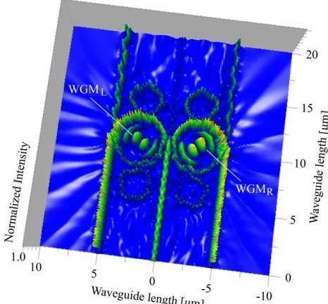
is the effective mode core area of the proposed device [24, 25]. The Optiwave computational software is used to perform the simulations utilizing the graphical method, where the selected parameters were used to obtain the whispering gallery mode at the center ring of the microring stereo system as shown in Figure 1, the graphical plot is shown in Figure 2. The used parameters are given in the figure captions. There are more parameters given in the related figure captions. The perfect stereo system output is plotted in Figure 3, the simulation tool is the Matlab program, where the completely mixed signals of the two systems from the right and left hands are obtained. In this case, the input power of the two system is the same and varied from 1-5 W. In case of the difference input power, the plot is shown in Figure 4, where the plot of the wavelength shift(∆𝜆) and the input light source wavelength(𝛌) has shown that the trend of the linearity is seen, the sensitivity of ~5.70 nm𝑊−1 is obtained. In Figure 5, the plot of Figure 4 in terms of the two-channel crosstalk is presented, which is more suitable for the description, when the system is filled by the two cell samples for both sensor and communication investigation. In the manipulation, the same cell (live cell) samples are put on the center of the Panda-ring resonators, where the cell samples interact with the WGM beams of each system, the reflected light beams are reverted to the stereo sensor system, which will be coupled to each other and the results obtained at the coupled drop port. By using the coupled equations between equations (3), (6), and (7), the center wavelengths of both systems and the crosstalk results are obtained. The change in the optical intensity will cause changes in the refractive index due to the Kerr effects. Therefore, a variation of the optical intensity will lead to changes in the OPD of the light in the system. Changing the light’s phase within the system can be due to the electron mobility caused by mixing the ChG ring with the metallic material, for an instant, silver, thus, the electron mobility (µ) in the ChG-silver can be changed [34, 35], from which the excited electrons are affected to the system output, which is related to the group velocity (Vd) of the waves, therefore the device acts as sensor. The
light intensity can be described by I=𝐸2 = ( 𝑉𝑑 𝜇)
2 as the V
d=µE and E is the applied electric field to the transducer as the
sensing system in which an electric current can be established with a density of Js as Js=σE. Generally, the electrical signal is
Figure 2: The graphical results of the wave propagation in the system in Figure 1 using the Optiwave program, where the input light source wavelength cenetr is at 1.55 µm, 𝑅𝑎1 = 𝑅𝑏1 = 𝑅𝑎2 = 𝑅𝑏2 = 1.2 µm, 𝑅𝑑1 = 𝑅𝑑2 = 2.0 µm, each of the coupling constant, 𝜅1 to 𝜅8 is 0.5, the
Figure 3: Plot of the stereo signal obtained from the tow systems, where (a) the left channel signal, (b) the right channel signal, (c) the mixed stereo signals.
Figure 4 : The plot the shift in phase of the stereo sensor system due to the Kerr-Vernier effect, which leads the shift in the center
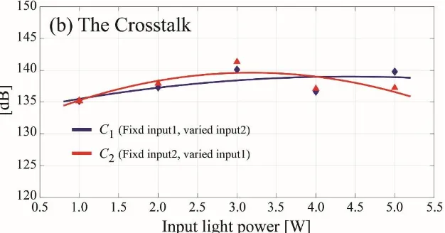
[image:6.612.153.460.261.427.2]Figure 5: Plot of the relationship of the change in the crosstalk and the input power, from which the Kerr-Vernier effect lead the shifted wavelength of the two channels, where one of the input power is fixed to 1 W, the another one is varied from 1 W to 5 W and the crosstalks of the two-channels in terms of 𝐶1 and 𝐶2 in an equation (7), which present the cell communication by the cross-coupling signals can be calculated and obtained.
Moreover, the large scale of the bio-cell communications called cellular automata can be implemented [38]. The comparative results of the microring stereo system are obtained at the coupling drop port as shown in Figure 1, from which the shift in the center peak signals from the stereo mixed signal outputs are the required measurement values. The stereo sensor is confirmed when the perfect mixing output is obtained. From the difference output variation, the coupling of the two-channel signals is occurred, which is the crosstalk signals of the two stereo channels. The crosstalk variation from both channels can be used to present the communication among the live cells. The optimum of the Kerr-Vernier effect depends on the ChG ring resonator length which is increased with the input power. The maximum change of 6 µm of ChG length could be obtained when the applied input power of 500 W was reported, the output wavelength was ranged from 1.5-4.5 µm[39]. However, in the proposed bio-cell sensor system, the applied input power is fixed while the small changed from the cell electrical transient of the stereo sensor is the required measurement quantity. The variation of the input power to obtain the change in the ChG is only for manipulation. There is an alternative method that can be used to study the proposed bio-cell communication when a similar system with two identical Panda-ring resonators are embedded by the plasmonic islands. A plasmonic island consisted of the stacked layers of silicon-graphene-gold materials[40-42], where the electron mobility sensitivity of ~ 2x10⁻¹⁴ 𝑚 𝑉−1𝑠−1 was obtained. The bio-cell samples are placed on the islands of each system, the coupling of the electrical transient of the two bio-cells samples caused the change in the island mobility that can be monitored and seen at the sensor outputs. The embedded island and its function within the system can be found in the reference[42].
The strong coupling of electromagnetic waves within an electric or magnetic dipole-carrying excitation generates the polaritons, are the quasiparticles [43]. It is the expression of the level of repulsion, which is the crossing of the dispersion of light with any interacting resonance. From the obtained results, the high energy light pulses of the coupling channels generated by the two different cell systems can be obtained by the nonlinear effect of the two side rings coupled to the center ring, which can present the strong coupling fields. The polariton is a bosonic quasiparticle, which is an electron plus an attached phonon cloud. A major feature of polaritons is a strong dependency of the propagation speed of light through the crystal on the frequency of the photon, which is the Rabi frequency. In human body is required by the network links between the brain and cell membrane signals, which involve the ion channels generated by the strong coupling between the photons and the excited ions(dipole-carrying excitation). The transmission of the polaritons with the specific Rabi oscillation can make the link between cell membrane-cell membrane and brain, where the cell communication can be performed.
4. Conclusion
[image:7.612.152.465.73.237.2]The initial crosstalks of the two systems are calculated and plotted. The stereo sensor sensitivity of ~5.70 nmW-1, the maximum crosstalk of 𝐶1 and 𝐶2 are ~2.0 and ~2.5 dB is calculated and obtained respectively.
Acknowledgement
The authors would like to give their acknowledgements to Ton Duc Thang University, Ho Chi Minh City, Vietnam for the use of laboratory and computer facilities. M.S. Aziz would like to acknowledge for the support and facilities under the UTM Shine Program. K. T. V. Grattan acknowledges the support of the George Daniels Educational Trust and the Royal Academy of Engineering.
References
[1] Z. Yang, S. Lu, T. Wu, G. Yuan, and Y. Tang, "Detection of morphology defects in pipeline based on 3D active stereo omnidirectional vision sensor," IET Image Processing, vol. 12, no. 4, pp. 588-595, 2018.
[2] S.-I. Oh and H.-B. Kang, "Fast Occupancy Grid Filtering Using Grid Cell Clusters From LIDAR and Stereo Vision Sensor Data,"
IEEE Sensors Journal, vol. 16, pp. 7258-7266, 2016.
[3] S. Kim, H. Kim, W. Yoo, and K. Huh, "Sensor fusion algorithm design in detecting vehicles using laser scanner and stereo vision,"
IEEE Transactions on Intelligent Transportation Systems, vol. 17, pp. 1072-1084, 2016.
[4] S. Koyama, K. Onozawa, K. Tanaka, S. Saito, S. M. Kourkouss, and Y. Kato, "Multiocular image sensor with on-chip beam-splitter and inner meta-micro-lens for single-main-lens stereo camera," Optics Express, vol. 24, pp. 18035-18048, 2016.
[5] M. Y. Kim, H. Lee, and H. Cho, "Dense range map reconstruction from a versatile robotic sensor system with an active trinocular vision and a passive binocular vision," Applied Optics, vol. 47, pp. 1927-1939, 2008.
[6] B. Sun, J. Zhu, L. Yang, Y. Guo, and J. Lin, "Stereo line-scan sensor calibration for 3D shape measurement," Applied Optics, vol. 56, pp. 7905-7914, 2017.
[7] K. Yang, K. Wang, H. Chen, and J. Bai, "Reducing the minimum range of a RGB-depth sensor to aid navigation in visually impaired individuals," Applied Optics, vol. 57, pp. 2809-2819, 2018.
[8] F. Zhou, X. Chai, X. Chen, and Y. Song, "Omnidirectional stereo vision sensor based on single camera and catoptric system,"
Applied Optics, vol. 55, pp. 6813-6820, 2016.
[9] Y. Sun, X. Yuan, and S. Pang, "Compressive high-speed stereo imaging," Optics Express, vol. 25, pp. 18182-18190, 2017.
[10] P. Phatharacorn, S. Chiangga, and P. Yupapin, "Analytical and simulation results of a triple micro whispering gallery mode probe system for a 3D blood flow rate sensor," Applied Optics, vol. 55, pp. 9504-9513, 2016.
[11] K. Chaiwong, K. Tamee, S. Punthawanunt, F. Suhailin, M. Aziz, J. Ali, et al., "Naked-eye 3D imaging model using the embedded micro-conjugate mirrors within the medical micro-needle device," Microsystem Technologies, pp. 1-5, 2017.
[12] N. Sarapat, T. Frank, and P. Yupapin, "Conjugate mirror design and simulation using a nonlinear coupling microring circuit," Journal of Nonlinear Optical Physics & Materials, vol. 22, p. 1350024, 2013.
[13] T. Saktioto, D. Irawan, P. P. Yupapin, and P. Phatharacorn, "A single eye 3D image perception device using vertical double ring resonator construction," Microwave and Optical Technology Letters, vol. 57, pp. 1802-1805, 2015.
[14] N. Thammawongsa and P. P. Yupapin, "Remote artificial eyes using micro-optical circuit for long-distance 3D imaging perception,"
Artificial cells, nanomedicine, and biotechnology, vol. 44, pp. 106-110, 2016.
[15] N. Pornsuwancharoen, P. Youplao, M. Aziz, J. Ali, I. Amiri, S. Punthawanunt, et al., "In-situ 3D micro-sensor model using embedded plasmonic island for biosensors," Microsystem Technologies, pp. 1-5, 2018.
[16] W. Wang, S. T. Chu, B. E. Little, A. Pasquazi, Y. Wang, L. Wang, et al., "Dual-pump Kerr micro-cavity optical frequency comb with varying FSR spacing," Scientific Reports, vol. 6, p. 28501, 2016.
[17] M. Bahadoran, J. Ali, and P. P. Yupapin, "Graphical approach for nonlinear optical switching by PANDA vernier filter," IEEE Photonics Technology Letters, vol. 25, pp. 1470-1473, 2013.
[18] I. Amiri and J. Ali, "Generating highly dark–bright solitons by Gaussian beam propagation in a PANDA ring resonator," Journal of Computational and Theoretical Nanoscience, vol. 11, pp. 1092-1099, 2014.
[19] I. Amiri, S. Alavi, M. Soltanian, N. Fisal, A. Supa’at, and H. Ahmad, "Increment of access points in integrated system of wavelength division multiplexed passive optical network radio over fiber," Scientific Reports, vol. 5, p. 11897, 2015.
[20] M. Soltanian, I. Amiri, S. Alavi, and H. Ahmad, "All optical ultra-wideband signal generation and transmission using mode-locked laser incorporated with add-drop microring resonator," Laser Physics Letters, vol. 12, p. 065105, 2015.
[21] S. Tunsiri, N. Thammawongsa, S. Mitatha, and P. P. Yupapin, "Molecular transport network security using multi-wavelength optical spins," Artificial Cells, Nanomedicine, and Biotechnology, vol. 44, pp. 240-247, 2016.
[22] F. D. Zainol, N. Thammawongsa, S. Mitatha, J. Ali, and P. Yupapin, "Nerve communication model by bio-cells and optical dipole coupling effects," Artificial Cells, Nanomedicine, and Biotechnology, vol. 41, pp. 368-375, 2013.
[23] G. B. Ferreira, M. Scheutz, and M. Levin, "Introducing simulated stem cells into a bio-inspired cell-cell communication mechanism for structure regeneration," in Computational Intelligence (SSCI), 2017 IEEE Symposium Series on, 2017, pp. 1-8.
[24] A. M. Prabhu, A. Tsay, Z. Han, and V. Van, "Extreme miniaturization of silicon add–drop microring filters for VLSI photonics applications," IEEE Photonics Journal, vol. 2, pp. 436-444, 2010.
[26] M. J. Faruki, M. Z. Ab Razak, S. R. Azzuhri, M. T. Rahman, M. R. K. Soltanian, G. Brambilla, et al., "Effect of titanium dioxide (TiO2) nanoparticle coating on the detection performance of microfiber knot resonator sensors for relative humidity measurement,"
Materials Express, vol. 6, pp. 501-508, 2016.
[27] I. Amiri, P. Naraei, and J. Ali, "Review and theory of optical soliton generation used to improve the security and high capacity of MRR and NRR passive systems," Journal of Computational and Theoretical Nanoscience, vol. 11, pp. 1875-1886, 2014.
[28] I. Amiri, S. Alavi, N. Fisal, A. Supa'at, and H. Ahmad, "All-Optical Generation of Two IEEE802. 11n Signals for 2$\times $2 MIMO-RoF via MRR System," IEEE Photonics Journal, vol. 6, pp. 1-11, 2014.
[29] I. Amiri, A. Nikoukar, and J. Ali, "GHz frequency band soliton generation using integrated ring resonator for WiMAX optical communication," Optical and Quantum Electronics, vol. 46, pp. 1165-1177, 2014.
[30] J. Neitzel and M. Rasband, "Cell Communication," Cell Biology. Nature Education, 2011.
[31] I. Amiri, M. Soltanian, S. Alavi, and H. Ahmad, "Multi wavelength mode-lock soliton generation using fiber laser loop coupled to an add-drop ring resonator," Optical and Quantum Electronics, vol. 47, pp. 2455-2464, 2015.
[32] S. Alavi, I. Amiri, H. Ahmad, A. Supa’at, and N. Fisal, "Generation and transmission of 3× 3 w-band multi-input multi-output orthogonal frequency division multiplexing-radio-over-fiber signals using micro-ring resonators," Applied Optics, vol. 53, pp. 8049-8054, 2014.
[33] F. Smektala, C. Quemard, L. Leneindre, J. Lucas, A. Barthélémy, and C. De Angelis, "Chalcogenide glasses with large non-linear refractive indices," Journal of Non-Crystalline Solids, vol. 239, pp. 139-142, 1998.
[34] S. Etienne, J. Perez, S. Peytavin, and M. Ribes, "Degrees of freedom and ionic mobility in silver chalcogenide glasses," Journal of Solid State Chemistry, vol. 92, pp. 27-38, 1991.
[35] S. Soysouvanh, M. Jalil, I. Amiri, J. Ali, G. Singh, S. Mitatha, et al., "Ultra-fast electro-optic switching control using a soliton pulse within a modified add-drop multiplexer," Microsystem Technologies, pp. 1-6, 2018.
[36] I. Timoshkin, S. MacGregor, R. Fouracre, B. Crichton, and J. Anderson, "Transient electrical field across cellular membranes: pulsed electric field treatment of microbial cells," Journal of Physics D: Applied Physics, vol. 39, p. 596, 2006.
[37] E. Niebur, "Electrical properties of cell membranes," Scholarpedia, vol. 3, p. 7166, 2008.
[38] D. Green, "Cellular automata models in biology," Mathematical and Computer Modelling: An International Journal, vol. 13, pp. 69-74, 1990.
[39] M. Karim, B. Rahman, and G. P. Agrawal, "Mid-infrared supercontinuum generation using dispersion-engineered Ge 11.5 As 24 Se 64.5 chalcogenide channel waveguide," Optics express, vol. 23, pp. 6903-6914, 2015.
[40] N. Pornsuwancharoen et al., “Micro-current source generated by a WGM of light within a stacked silicon-graphene-Au waveguide”, IEEE Photon. Technol. Lett. Vol. 19, no. 21, pp. 1768-1771, 2017.
[41] N. Pornsuwancharoen, P. Youplao, I.S. Amiri , M.S. Aziz, Q.L. Tran, J. Ali, and P. Yupapin, K.T.V. Grattan, "Multifunction interferometry using the electron mobility visibility and mean free path relationship", Microscopy Research and Techniques, pp. 1-7, 2018, inpress.
[42] N. Pornsuwancharoen, P. Youplao, I.S. Amiri, M.S. Aziz, J. Ali, G. Singh, P. Yupapin, V. Koledov, K.T.V. Grattan, "Electron mobility sensor scheme based on a Mach Zehnder interferometer approach", IEEE Photon. Technn. Lett., vol. 30, no. 10, pp. 887-890, 2018.