Rochester Institute of Technology
RIT Scholar Works
Theses
Thesis/Dissertation Collections
2006
Routing in Anhinga
Aakash Chauhan
Routing in Anhinga
Master’s Project Report
Aakash Chauhan
Department of Computer Science,
Rochester Institute of Technology
Chairman
:
Prof.
Hans-Peter
Bischof
Date
Reader: Prof. Alan Kaminsky Date
1. Abstract ... 3
2. Overview... 4
2.1 Architecture of Anhinga Infrastructure ... 4
2.2 Why this project is needed ... 4
2.3 MANET
protocols ... 5
3. Proposed Protocol and Working ... 6
3.1 What is DSR Protocol... 7
3.2 Working Of DSR Protocol... 7
3.2.1 Route
Discovery... 8
3.2.2 Route
Maintenance ... 9
4. Architectural Overview ... 10
4.1 Existing M2MP Architecture... 11
4.2 Existing M2MI Architecture ... 12
4.3 Project
Architecture ... 13
4.4 Routing
Algorithm ... Error! Bookmark not defined.
5. Design Specifications ... 22
5.1 Class Description package edu.rit.m2mp.dsr ... 22
5.2 Modification in package edu.rit.m2mp... 30
5.3 Modification in package edu.rit.m2mi... 34_Toc147122631
5.4 Package
edu.rit.m2mi.chat2 ... Error! Bookmark not defined.
6 User
Guide ... 40
6.1 System
Requirements... 40
6.2 How to Configure... 40
6.3 How to Start ... 42
6.3.1 Running
M2MP Daemon ... 42
6.3.2 Running
DSR Router ... 42
6.3.3 Running
Test Application ... 43
7 Testing and Benchmarking... 44
7.1 DSR Test Results ... 44
1.
Abstract
2.
Overview
2.1
Anhinga
3The Anhinga Project is the distributed computing infrastructure designed with
supporting collaborative applications running in mobile ad hoc networks.
Anhinga provides infrastructure for mobile wireless computing devices such as
laptop computers, cell phones, pocket PCs that runs completely on the mobile
device. Unlike traditional middleware infrastructure for networking technologies
which require central servers and wired connections, anhinga runs on mobile
devices and does not require central server to run collaborative applications in
mobile environment.
Anhinga is built on two major components, Many-to-Many Protocol (M2MP) and
Many-to-Many Invocation (M2MP). M2MP is a message broadcasting protocol
designed with serverless ad hoc networks of small devices in mind. M2MI is built
on top of M2MP. M2MI is object oriented abstraction of broadcast method
invocation. M2MI allows a method invocation across the devices and through out
the network. M2MI can simply be described as “All the devices out there who
implement this interface, execute this method.”
The architecture of Anhinga and M2MP & M2MI in particular is described in detail
in later sections.
2.2
Why this project is needed
This project takes aim at combining these two. Meaning putting an existing
MANET routing protocol into anhinga and make two nodes in geographically
dispersed network communicate via M2MP.
2.3
Various MANET protocols
Ad hoc network is a collection of wireless mobile hosts that dynamically form a
temporary network where any node can join or leave the network without any prior
notification. It has no fixed infrastructure. It is formed and deformed on the fly,
depending on the need of the mobile users. There is extensive research being done
in routing in these Mobile Ad Hoc Networks (MANET). In such mobile networks
battery power and bandwidth are very limited. The research done concentrates on
minimum protocol overhead with quick adaptability to rapidly changing network
topology.
Major categorization of MANET protocols is as follows:
1.
Pro-active (Table- Driven) -
Pro-active (Table-driven) protocol tries to maintain consistent view of routes to all
possible nodes from a given node. The protocol tries to maintain these routes even
before they are ever needed or used. The Destination-Sequenced Distance-Vector
Routing (DSDV) protocol is a table driven algorithm that modifies the
Bellman-Ford routing algorithm to include timestamps that prevent loop-formation. The
Wireless Routing Protocol (WRP) is a distance vector routing protocol which
belongs to the class of path-finding algorithms that exchange second-to-last hop to
destinations in addition to distances to destinations. Since these type of protocol try
to keep track of all the changes in network topology, there is significant routing
overhead is attached to this class of MANET routing protocols.
On-demand routing protocols try to reduce control overhead, thus decreasing
bandwidth and power usage. These protocols limit the amount of bandwidth
consumed by maintaining routes to only those destinations for which a source has
data traffic. Therefore, the routing is source-initiated as opposed to table-driven
routing protocols that are destination initiated. This type of protocol also avoids
heartbeats between nodes since they do not try to maintain complete network
topology. There are several examples of this approach (e.g., DSR, ABR, AODV,
TORA, SSA, ZRP) and the routing protocols differ on the specific mechanisms used
to reduce flood search packets and their responses, cache the information heard
from other nodes’ searches, determine the cost of a link, and determine the
existence of a neighbor.
3.
Hybrid (Pro-Active/Reactive) –
3.1
What is DSR Protocol
The Dynamic Source Routing protocol (DSR) is a simple and efficient on-demand
(reactive) routing protocol. Unlike lot of other protocols DSR does not maintain
network topology, which allows the network to be completely self-organizing and
self-configuring, without the need for any existing network infrastructure or
administration. There are two major mechanisms in DSR, 'Route Discovery' and
'Route Maintenance'. These two together allow nodes to discover and maintain
routes to any destinations in an ad hoc network. Since this protocol works
completely on-demand, the overhead scales automatically to changes in the
network and nothing else. This allows overhead less protocol when all nodes are
stationary in the topology and scales up with topological changes. The protocol
allows multiple routes to any destination and allows each sender to select the route
used in routing its packets. The route discovery mechanism guarantees loop-free
routes. DSR also works in networks with unidirectional link.
The protocol was designed with mobile ad hoc networks in mind, where battery
power and bandwidth are expensive. To restrict unnecessary bandwidth usage and
processing power, DSR does not initiate a route discovery until it is needed and
initiated by a node. Similarly once a route is found there is no effort is put in
maintaining that route. Route availability or new route search is only initiated when
a route error occurs for existing route and some node initiates a new route
discovery process to that same destination. Unlike other reactive routing protocols
like ABR or SSA, DSR does not require heart beat message between neighbors to
maintain network topology.
DSR is based on the Link-State-Algorithms which mean that each node is capable to
save the best way to a destination. Also if a change appears in the network
topology, then the whole network will get this information by flooding.
As discussed earlier there are two major components of DSR,
1)
Route Discovery, which consists of
a.
Route Request
b.
Route Reply
2)
Route Maintenance
General workings of these are discussed in the following section. A detailed discussion
about implementation and working of these mechanisms is done in section 4.
3.2.1
Route Discovery
When a node wants to send a message, it first checks its route cache table for a route to
destination. If no route found then an automatic route discovery process is initiated.
The node seeking the route sends out route request message. When a node receives a
route request message, it adds itself to the source route and rebroadcasts the request.
Once the request reaches the intended destination node, destination node adds itself to
the route and initiates a route reply message. Section 4 discusses the detail working of
route request and route reply.
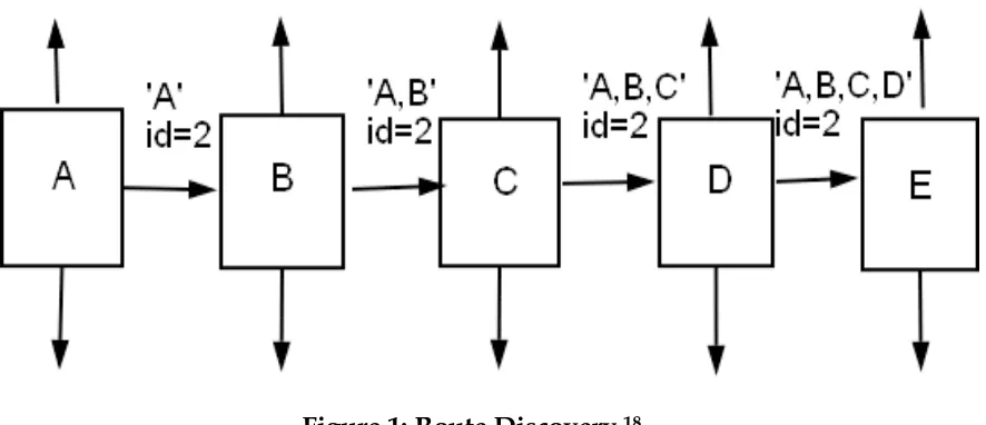
Figure 1: Route Discovery
18If node A has in his Route Cache a route to the destination E, this route is used. If not,
the Route Discovery protocol is started:
a)
Node A (initiator) sends a RouteRequest packet by flooding the network
b)
If node B has recently seen another RouteRequest from the same target or if the
address of node B is already listed in the Route record, then node B discards the
request.
c)
If node B is the target of the Route Discovery, it returns a RouteReply to the
initiator. The RouteReply contains a list of the “best” path from the initiator to
the target. When the initiator receives this RouteReply, it caches this route in its
Route Cache for use in sending subsequent packets to this destination.
d)
Otherwise node B isn’t the target and it forwards the RouteRequest to his
neighbors (except to the initiator).
3.2.2
Route Maintenance
so that it can remove that Source Route from its Route Cache. If there is no route in
the cache, a RouteRequest packet is broadcasted. Also if there was any other route in
the route cache that was using exact same broken link then all those routes are
invalidated. Figure 5 shows an example,
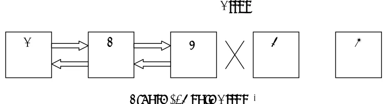
Figure 2: Route Error
181.
If node C does not receive an acknowledgement from node D after some number
of requests, it returns a RouteError to the initiator A.
2.
As soon as node receives the RouteError message, it deletes the
broken-link-route from its cache. If A has another broken-link-route to E, it sends the packet immediately
using this new route.
3.
Otherwise the initiator A is starting the Route Discovery process again.
Details about this route process are discussed in section 4.
A
B
C
D
E
4.1
Existing M2MP Architecture
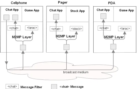
3The Many-to-Many Protocol is designed for the wireless proximal ad hoc networking
environment. Following points highlight major features of M2MP architecture:
•
There are no device addresses. M2MP works in broadcast medium. Consequently,
devices can enter and leave the network in an ad hoc fashion without having to do
network configuration.
•
Messages are broadcast to all devices. Instead of point to point communication, all
the messages in M2MP are broadcasted taking inherent advantage of wireless
communication medium in wireless ad hoc network.
•
A message’s relevancy is determined by its contents. A node determines if a
particular message is of its interest based on its content.
Figure 3: M2MP Architecture
34.2
Existing M2MI Architecture
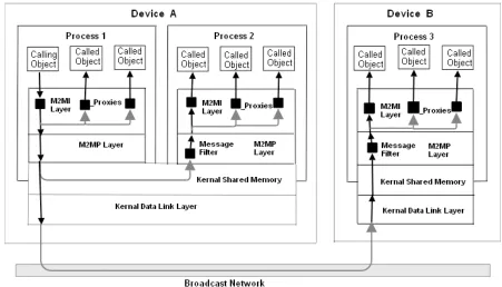
3eliminating the need to compile and deploy proxies ahead of time. Because of
dynamic proxy, central servers are not required; which eliminates lot of network
administration. Also since M2MI works in pure broadcasting environment,
complicated, resource-consuming ad hoc routing protocols are not required.
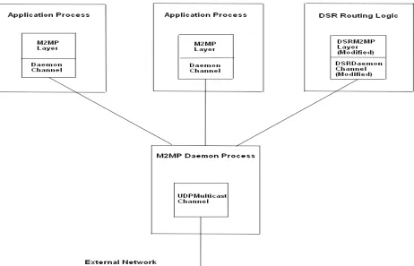
[image:14.612.90.541.275.533.2]M2MI provides object oriented abstraction of message broadcasting. An
application can invoke a method declared inside an interface on multiple objects on
multiple devices at same time using M2MI. For further information on M2MI
architecture please refer to, http://www.cs.rit.edu/~anhinga/m2mi.shtml
Figure 4: M2MP & M2MI Architecture
34.3
Project Architecture
DSR Router process. Just like all other M2MP processes, DSR Layer receives all the
messages received by this node via the M2MP Daemon Channel. Unlike a normal
M2MP process, where it filters out messages based on the message prefix, the
routing layer processes each message it receives. Once a message is received, it is
handed off to Routing Engine.
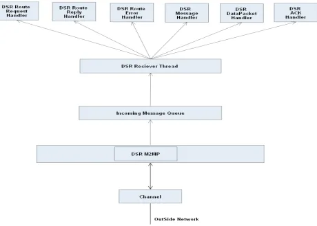
Figure 6: Routing Layer Architecture
16As shown in Figure 6 above, once the routing engine receives routing protocol
packets from outside, it process it as per protocol rules, updates local tables and
rebroadcasts them back if necessary. Figure 7 shows all the class level details of
routing layer and what routing rules are implemented.
Routing Engine
DSRM2MP
(Forwards Packets)
Daemon Process /
Channel
Routing Protocol
Processes
Packet
In
Packet
Out
Forwarding
Table
Updates
Routing
Protocol
Packets
4.4
Routing Algorithm
In summary when a node wants to send a targeted message to a particular
destination, it checks its route cache for answers. If no route found a route request
is initiated.
a)
Decision making process about a packet received
b)
“Route Request” packet received
c)
“Route Reply” packet received
For a new route reply message received from node other then self, the source route
is extracted out of the message. After that if this node was the intermediate
intended receiver of this message then it rebroadcasts it back for final destination.
d)
“Route Error” packet received
5.
Design Specifications
This section discusses different packages in the API of the framework. As explained in
the architecture there are four major layers / components in the implementation, DSR
layer, M2MP layer, M2MI layer and application layer. The list of packages and their
description is as follows:
a) edu.rit.m2mp.dsr – This package is the routing layer. It is the brain of routing
mechanism.
b) edu.rit.m2mp – This is the original anhinga layer that provides Many-to-Many
protocol implementation.
c) edu.rit.m2mi – This is the Many-to-Many invocation layer running on top of
M2MP.
d) edu.rit.m2mi.chat2 – This is the test application written on top of M2MI to test
the routing mechanism.
5.1 Class Description package edu.rit.m2mp.dsr
(i)
class DSRACKHandler
(ii)
class DSRCommonConstants
This class defines common constants used throughout the DSR Router engine. It define
generic old style M2MP/M2MI Data Packet constant (DATA_PACKET), DSR Route
Request Packet constant (ROUTE_REQUEST), DSR Route Reply packet constant
(ROUTE_REPLY), DSR Data Packet constant (DSR_DATA_PACKET), DSR
Acknowledge Packet constant (DSR_ACK_PACKET), DSR Route Error Packet constant
(DSR_ROUTE_ERROR).
(iii)
class DSRDataPacketHandler
(iv)
class DSRException
DSRException indicates that the DSR Layer failed because a certain Runtime values.
(v)
class DSRM2MP
Class DSRM2MP does same functionality for DSR Routing engine as regular M2MP
does for classical anhinga. It provides DSR M2MP Layer. It holds important data
structures like Route Cache Map that contains all valid routes known to this node. It
also holds recently processed messages map, which is used to eliminate duplicate
messages. This class is the entry point for any incoming message. Upon receiving any
incoming message this if its a new non-duplicate message, a new MessageInputStream
is created and message is queued in incoming message queue. The DSRReceiverThread
constantly keeps scanning this message queue and works on each incoming message.
This class also provides interface between outgoing channel and DSR routing engine.
This is accomplished by exposing methods like createOutgoingMessage,
rebroadcastRouteReply, sendRouteReply, rebroadcastRouteRequest,
rebroadcastDSRDataPacket, rebroadcastDSRACKPacket, searchRouteCache and
(vi)
class
DSRM2MPProperties
Class DSRM2MPProperties provides access to properties that are used to configure the
DSR Layer.
(vii)
class DSRMessageHandler
(viii)
class DSROptions
This class defines options attached each DSR packet. This option packet when attached
to traditional Anhinga packet defines type of DSR packet. This class also provides lot of
useful DSR message related functionality like, next intermediate address, final target
destination, message origin address.
DSRRouteReplyHandler object is created and this MessageInputStream is passed to it to
process the message appropriately.
If the M2MI property "edu.rit.m2mi.debug.ReceiverThread" is 1 or higher, then
whenever an exception is thrown while receiving or processing an incoming M2MI
invocation message, the receiver thread will print the exception stack trace on the
standard error stream. The receiver thread will continue running, however.
If the M2MI property "edu.rit.m2mi.debug.ReceiverThread" is 2 or higher, then the
receiver thread will print a message on the standard error stream whenever the receiver
thread receives an incoming M2MI invocation message.
(x)
class DSRRouteErrorHandler
This class processes incoming DSR Route Error message. It first checks if this message is
already processed. If yes then discards it. Otherwise based on the faulty route reported,
route table is updated.
This class is the starting point of DSR Router. It initializes the DSRM2MP Layer and
starts the receiver thread by passing it the DSRM2MP layer object. This class contains
the main method that starts the DSR Routing engine and keeps it alive till killed.
(xii)
class DSRRouteReplyHandler
This class processes incoming DSR Route Reply message. For non-duplicate messages it
will add the route to its own route cache if this node is part of the source route of route
reply message. The route reply message is rebroadcast if this node was not original
sender and the next intended receiver for this route reply was this node.
(xiii)
class DSRRouteRequestHandler
(xiv)
class DSRUtil
This class provides common useful functionality across the DSR Routing layer.
(xv)
class DuplicateRouteRequestException
Class DuplicateRouteRequestException indicates that the upper layer is trying to
initiate a duplicate route request.
(xvi)
interface DSRServices
5.2
Modification in package edu.rit.m2mp
(i)
class M2MP
The Packet class has been updated extensively to accommodate DSR related data in
each packet. Major fields added are,
A)
Packet Type: Type of the packet. Value to this is assigned from
DSRCommonConstants.
B)
Hop Count: Maximum # of allowed rebroadcasts for this packet.
C)
Sender ID: Who originally sent out this packet
(iii)
class MessageInputStream
(iv)
class MessageOutputStream
Changes necessary based on changes in each Packet. Various methods modified to
reflect changes related to format of each packet. Also various constructors added to
accommodate specific type of messages.
5.3
Modification in package edu.rit.m2mi
(i)
class M2MI
(ii)
class ReceiverThread
5.4
Package edu.rit.m2mi.chat2
(i)
interface Chat
Interface Chat specifies the interface for a rudimentary M2MI-based chat object. It is
same as in original ChatDemo1 application except that identityResponse() is added to
accommodate display of neighbors list.
(ii)
interface ChatFrameListener
Interface ChatFrameListener specifies the interface for an object that is triggered when
the user sends a line of text in a link ChatFrame
(iv)
class ChatDemo2
Class ChatDemo2 is a rudimentary M2MI-based chat application. The program displays
a simple chat UI that implements interface. As in original ChatDemo1 application when
the user sends a line of text in the UI, the line is broadcast to all the chat objects by
calling putLine() on an omnihandle for interface Chat. When each chat object receives a
putLine() invocation, it displays the line of text in the chat log in its UI.
(v)
class ChatFrame
(vi)
class ChatObject
Class ChatObject is exact same as in chat1 package. Except that it adds extra functions
to manage route request and route discoveries received from lower levels.
(vii)
class NeighborsListGUI
6
User Guide
This section describes user manual for routing protocol implemented.
6.1
System Requirements
The system is tested on following configuration.
•
Sun Solaris OS running on SUN SPARC architecture
•
J2SDK 1.4.2
•
M2MP/M2MI library version 2004/03/02
System will run on any other OS with java version 1.4.2 or higher running on it. DSR
router is note tested for M2MP / M2MI APIs version later then 2004/03/02.
6.2
How to Configure
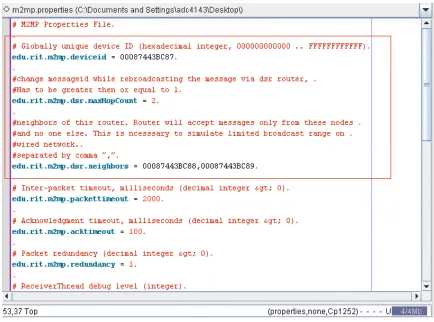
Figure 8: Configuration file (m2mp.properties)
For specifics about configuring M2MP layer please refer to respective documentation at,
http://www.cs.rit.edu/~anhinga/m2miapi20040302/doc/edu/rit/m2mp/package-summary.html#configuring
Following three properties are very important in deciding behavior of DSR router.
•
edu.rit.m2mp.deviceid –
The globally unique device ID of the device on which the
M2MP Layer is running. It is same as mentioned in configuration for M2MP layer. It
must be a 48-bit hexadecimal integer in the range
000000000000through
FFFFFFFFFFFF.
to identify itself with neighbors and to identify its own neighbors for node-to-node
communication.
•
edu.rit.m2mp.dsr.maxHopCount = 2 –
Maximum number of network hops up to
which this packet will be re-broadcasted. This value is used when hop count is not
mentioned programmatically when sending out a message. This is important for
backward compatibility. M2MI messages written before DSR Router inclusion will
use this property value as default. Value of this property should be 1 or higher.
•
edu.rit.m2mp.dsr.neighbors –
This property value defines neighbors for this given
node. This host will accept packets sent by nodes that are in this list. Any packets
received from nodes other then in this list are discarded. The neighbors are
mentioned using their unique device ID. This property is needed to simulate
dispersed network on a wired broadcast network.
6.3
How to Start
6.3.1
Running M2MP Daemon
For DSR router to run successfully, M2MP Layer must be configured to use M2MP
Daemon. M2MP Daemon must be started in a separate process before running DSR
Router or any other M2MP or M2MI based application. To start M2MP Daemon,
>java edu.rit.m2mp.Daemon
6.3.3
Running Test Application
After starting Daemon channel and DSR Router in sequence, any M2MP or M2MI based
application can be started. To start Chat Demo application, developed as part of this
project to test APIs can be started as follows,
7
Testing and Benchmarking
System was tested in Computer Science lab on Sun Solaris operating system with Java
1.5.0.
7.1
DSR Test Results
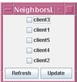
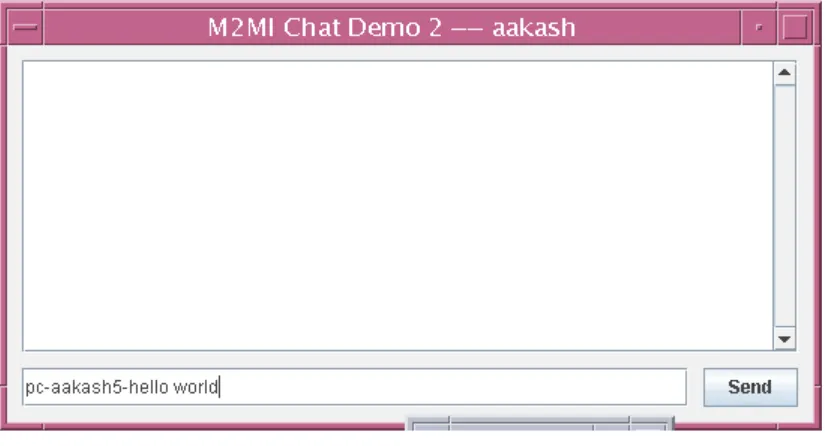
[image:45.612.238.374.279.424.2]A custom chat application was written based on Chat application from Anhinga. The
chat application allowed sending messages using a GUI as well as programmatically. At
startup of chat application a window shows available neighbors a node can chat with in
the network.
Figure 9: Available Neighbors
Figure 10: Private Chat
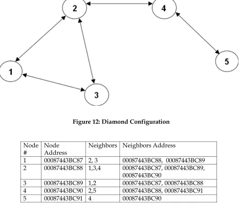
[image:46.612.101.514.394.610.2]The application was tested on 2 different network topologies. One is the diamond like
network topology as shown in Fig 18. Second was linear network as shown in Fig. 19.
Figure 11: Route Discovery
7.1.1
Diamond Configuration
Figure 12: Diamond Configuration
Node
#
Node
Address
Neighbors Neighbors Address
1 00087443BC87 2, 3
00087443BC88, 00087443BC89
2 00087443BC88 1,3,4 00087443BC87,
00087443BC89,
00087443BC90
3 00087443BC89 1,2 00087443BC87,
00087443BC88
4 00087443BC90 2,5 00087443BC88,
00087443BC91
[image:47.612.111.501.368.489.2]5 00087443BC91 4 00087443BC90
the time of message being sent. The route cache is incremental and is valid through out
the table from first message up to the last message.
Diamond Like Network
Sender Of Message : Client 1 Cache content of Each Client at End of Route Request
To Client 1 Client 2 Client 3 Client 4 Client 5
Client 5
Route Search Time (Avg) 5291 ms 87->88->90->91 88->90->91
Data Transfer Time (Avg) 647 ms To Client 4
Route Search Time (Avg)
355
ms 87->88->90
Data Transfer Time (Avg) 361 ms To, Client 3
Route Search Time
(Avg) 0 ms
Data Transfer Time (Avg) 254 ms To, Client 2
Route Search Time
(Avg) 0 ms
Data Transfer Time (Avg)
168
ms
Sender Of Message : Client 2
To
Client 5
Route Search Time
(Avg) 0 ms
Used From
Cache
Data Transfer Time (Avg) 344 ms To Client 4
Route Search Time
(Avg) 0 ms
Used
Cache
Data Transfer Time (Avg) 138 ms To, Client 3
Route Search Time
(Avg) 0 ms
Data Transfer Time (Avg) 121 ms To, Client 1
Route Search Time
(Avg) 0 ms
Data Transfer Time (Avg)
158
ms
Sender Of Message : Client 3
To
Client 5
Route Search Time (Avg)
571
ms
Replies From
Cache 89->88->90->91
Data Transfer Time (Avg) 600 ms To Client 4 Replies From
Cache 89->88->90
Route Search Time (Avg)
401
ms
Data Transfer Time (Avg) 138 ms To, Client 2
Route Search Time
(Avg) 0 ms
Data Transfer Time (Avg)
128
Data Transfer Time (Avg) 139 ms
Sender Of Message : Client 4
To
Client 5
Route Search Time
(Avg) 0 ms
Used From
Cache Data Transfer Time
(Avg) 161 ms To Client 3
Route Search Time (Avg)
338
ms
Replies From
Cache 90->88->89
Data Transfer Time (Avg) 346 ms To, Client 2
Route Search Time
(Avg)
Data Transfer Time (Avg) 122 ms To, Client 1
Route Search Time (Avg)
386
ms
Replies From
Cache 90->88->87
Data Transfer Time (Avg)
388
ms
Sender Of Message : Client 5
To
Client 4
Route Search Time
(Avg) 0 ms
Data Transfer Time (Avg) 125 ms To Client 3
Data Transfer Time (Avg) 346 ms To, Client 2
Route Search Time (Avg)
334
ms
Replies From
Cache 91->90->88
Data Transfer Time (Avg) 371 ms To, Client 1
Route Search Time (Avg)
9008
ms
Replies From
Cache 91->90->88->87
Data Transfer Time (Avg)
9009
[image:51.612.32.573.68.302.2]ms
Table 2: Test Results for Diamond topology
7.1.2
Linear Configuration
Second topology that was used to test the routing protocol was the simple linear
network topology.
[image:51.612.105.550.496.559.2]# Address
1 00087443BC87 2 00087443BC88
2 00087443BC88 1,3 00087443BC87,
00087443BC90
3 00087443BC90 2,4 00087443BC88,
00087443BC91
[image:52.612.113.501.71.149.2]4 00087443BC91 3 00087443BC89
Table 3: Linear Configuration
Following table shows test results for the linear network topology. As in the previous
test, the time it takes to find a route to a destination and the time it takes to send data
packet to that destination and receiving confirmation is measured.
Linear Network
Sender Of Message : Client 1 Cache content of Each Client at End of Route Request
To Client 1 Client 2 Client 3 Client 4
Client 4
Route Search Time
(Avg) 7135 ms 87->88->90->91 88->90->91
Data Transfer Time
(Avg) 611 ms
To
Client 3
Route Search Time
(Avg) 337 ms 87->88->90
Data Transfer Time
(Avg) 437 ms
To,
Client 2
Route Search Time
(Avg) 0 ms
Data Transfer Time
(Avg) 132 ms
Sender Of Message : Client 2
To,
Client 4
Route Search Time
(Avg) 0 ms
Data Transfer Time
(Avg) 353 ms
To,
Client 3
Data Transfer Time
(Avg) 140 ms
To,
Client 1
Route Search Time
(Avg) 0 ms
Data Transfer Time
(Avg) 205 ms
Sender Of Message : Client 3
To,
Client 4
Route Search Time
(Avg) 0 ms
Data Transfer Time
(Avg) 136 ms
To,
Client 2
Route Search Time
(Avg) 0 ms
Data Transfer Time
(Avg) 125 ms
To,
Client 1
Route Search Time
(Avg) 348 ms 90->88->87
Data Transfer Time
(Avg) 400 ms
Sender Of Message : Client 4
To,
Client 3
Route Search Time
(Avg) 0 ms
Data Transfer Time
(Avg) 126 ms
Data Transfer Time
(Avg) 125 ms
To,
Client 1
Route Search Time
(Avg) 614 ms
Replied from
Cache 91->90->88->87 Data Transfer Time
[image:54.612.56.555.66.187.2](Avg) 656 ms
Table 4: Test Results for Linear Topology
This project was designed and developed with enabling communication between nodes
in dispersed network in mind. Even though this implementation provides APIs for
application on top of it to use, a great deal can be improved to provide infrastructure for
applications on top to use its core functionality. Another major changes can be done is
the way in which peer-to-peer messages are transmitted. Currently all the messages are
broadcasted in local network rather then being uni-casted or multi-casted. This change
may affect the performance of the system in a major way. Following are some other
points on which project can be enhanced in future.
1)
“Salvaging Packets”:
When broadcasting a “Route Error” packet, if a node has
alternate path to broken link in its cache; it piggy backs the replacement route with
“Route Error” page.
2)
“Automatic Route Shortening”:
A route can be automatically shortened if a node
over hears a packet carrying a source route, it examines node’s unused route, and if
it finds itself in there, that means that the node immediately before it in the route is
not needed. In such case this node will return “gratuitous Route Reply” to source
node with shortened route.
3)
Increased spreading of “Route Error” message:
Piggy backs a “Route Error” packet
to corresponding “Route Request” packet so that neighbor nodes do not reply with
old route from their cache. And they update their own route cache.
Source node caches negative information. Meaning the node that requested “Route
Request” based on previous “Route Error” will cache information of broken link
from “Route Error” for certain amount of time. This will allow the node to discard
any “Route Reply” based on stale cache.
[1] Alan Kaminsky and Hans-Peter Bischof. Many-to-Many Invocation: A new object
oriented paradigm for ad hoc collaborative systems. 17th Annual ACM Conference on
Object Oriented Programming Systems, Languages, and Applications (OOPSLA 2002),
Onward track, Seattle, Washington, USA, November 2002,
http://www.cs.rit.edu/~anhinga/publications/m2mi20020716.pdf
[2] AD HOC Networking, Charles E. Perkins, editor, Boston, MA: Addison-Wesley,
2001.
[3] The Anhinga Project.
http://www.cs.rit.edu/~anhinga.
[4] Routing Protocols in Mobile Ad Hoc Networks. Aakash Chauhan, Research/Review
paper for Data Communication and Networks - 1. RIT. Winter 2002.
http://www.rit.edu/~adc0467/dcn1Paper.pdf
[5] J.J. Garcia-Luna-Aceves and Marcelo Spohn “Source-Tree Routing in Wireless
Networks” In Proceedings of IEEE ICNP 99: 7th International Conference on Network
Protocols, Toronto, Canada, October 31-November 3, 1999.
[6] Zygmunt J. Haas and Marc R. Pearlman. “ZRP: A Hybrid Framework for Routing in
Ad Hoc Networks.” In Charles E. Perkins, editor, Ad Hoc Networking (Boston, MA:
Addison-Wesley, 2001). Pages 221-253.
[9] David B Johnson, David A Maltz and Josh Broch. “Dynamic Source Routing Protocol
for Multihop wireless Ad Hoc Networks.” In Charles E. Perkins, Ad Hoc Networking
pg. 139-172.
[10] Sung J Lee, William Su and Mario Gerla. “On-Demand Multicast Routing Protocol
(ODMRP) in Multihop Wireless Mobile Networks.”
http://citeseer.nj.nec.com/cache/papers/cs/20405/http:zSzzSzwww.cs.ucla.eduzSzN
RLzSzwirelesszSzPAPERzSzsjlee_monet.pdf/lee01demand.pdf
[11] Java On-Demand Multicasting Routing Protocol (JOMP)
http://homepages.cs.ncl.ac.uk/einar.vollset/home.formal/jomp.html
[12] DSR Routing Simulator: An exploration into ad-hoc Routing
http://www.cs.rit.edu/~ark/543/teams/Aquafina/
[13] IETF DSR Draft
http://www.ietf.org/internet-drafts/draft-ietf-manet-dsr-10.txt
[14] HF-DSR: Dynamic Source Routing for High Frequency Radio Networks
http://www.cs.rit.edu:8080/ms/static/ark/2005/3/mds1761/index.html
[15] http://wiki.uni.lu/secan-lab/Dynamic+Source+Routing.html
[16]
http://www.juniper.net/techpubs/hardware/m10i/m10i-hwguide/architecture-re.html#fig-architecture-re
[17] http://www.cs.cmu.edu/~dmaltz/dsr.html